Universal wheel
US20180099555A1
2018-04-12
15/836,899
2017-12-10
✅ Patent granted
US 10,384,531 B2
2019-08-20
-
-
Jeffrey O'Brien
Leong C. Lei
2037-12-10
Abstract:
The universal wheel includes a base member, a vertical axle, a lift member, and a wheel member. The lift member adjusts the universal wheel's height. A first driving element, a second driving element, and an engaging element are configured on the base member and the wheel member. The first driving element for turning the base member laterally within 360 degrees. The second driving element is for rolling the wheel member around its lateral axle. The engaging element couples or decouples an external shaft with the lateral axle of the wheel member. As such, through the first and second driving elements, and the engaging element, the universal wheel can control a height from the ground and can be rolled forward, laterally, obliquely, turned 360 degrees when standing in place, or in a combination of these operations.
Inventors:
- CHUN-HSIANG YANG 7 🇹🇼 Taipei, Taiwan
- CHUN-HSIANG YANG 4 🇹🇼 Taipei City, Taiwan
- Hsiu-Fang Chang 2 🇹🇼 Taipei City, Taiwan
- Hsiu-Fang Chang 1 🇹🇼 Taipei, Taiwan
Applicant:
Interested in similar patents?
Get notified when new applications in this technology area are published.
Classification:
B60G2500/30 » CPC further
Indexing codes relating to the regulated action or device Height or ground clearance
B60G17/00 » CPC further
Resilient suspensions having means for adjusting the spring or vibration-damper characteristics, for regulating the distance between a supporting surface and a sprung part of vehicle or for locking suspension during use to meet varying vehicular or surface conditions, e.g. due to speed or load
F16D11/14 » CPC further
Clutches in which the members have interengaging parts with clutching members movable only axially
B60K7/0007 » CPC main
Disposition of motor in, or adjacent to, traction wheel the motor being electric
B62D5/0418 » CPC further
Power-assisted or power-driven steering electrical, e.g. using an electric servo-motor connected to, or forming part of, the steering gear Electric motor acting on road wheel carriers
B60K2007/003 » CPC further
Disposition of motor in, or adjacent to, traction wheel with two or more motors driving a single wheel
B60K2007/0038 » CPC further
Disposition of motor in, or adjacent to, traction wheel the motor moving together with the wheel axle
B60K2007/0084 » CPC further
Disposition of motor in, or adjacent to, traction wheel the motor axle being perpendicular to the wheel axle the motor axle being vertical
B60K2007/0092 » CPC further
Disposition of motor in, or adjacent to, traction wheel the motor axle being coaxial to the wheel axle
B62B5/004 » CPC further
Accessories or details specially adapted for hand carts; Propulsion aids; Electric motors; Arrangements of motors in wheels
B60K7/00 IPC
Disposition of motor in, or adjacent to, traction wheel
B62D5/04 IPC
Power-assisted or power-driven steering electrical, e.g. using an electric servo-motor connected to, or forming part of, the steering gear
B62D7/026 » CPC further
Steering linkage; Stub axles or their mountings for pivoted bogies characterised by comprising more than one bogie, e.g. situated in more than one plane transversal to the longitudinal centre line of the vehicle
B60B33/026 » CPC further
Castors in general; Anti-clogging castors with disengageable swivel action, i.e. comprising a swivel locking mechanism being actuated remotely, e.g. by cable or electrically
B62B5/00 IPC
Accessories or details specially adapted for hand carts
B60B33/00 IPC
Castors in general; Anti-clogging castors
B60B33/02 IPC
Castors in general; Anti-clogging castors with disengageable swivel action, i.e. comprising a swivel locking mechanism
B62D7/02 IPC
Steering linkage; Stub axles or their mountings for pivoted bogies
B60K17/30 » CPC further
Arrangement or mounting of transmissions in vehicles the ultimate propulsive elements, e.g. ground wheels, being steerable
B60B33/0018 » CPC further
Castors in general; Anti-clogging castors assembling to the object, e.g. furniture characterised by adaptations made to castor in the form of a flat mounting plate
Description
CROSS-REFERENCE TO RELATED APPLICATION
This application is a continuation-in-part of U.S. patent application Ser. No. 15/173,617, filed Jun. 4, 2016, the disclosure of which are incorporated herein by reference in their entireties.
BACKGROUND OF THE INVENTION
(a) Technical Field of the Invention
The present invention is generally related to universal wheels, and more particular to a universal wheel whose height may be adjusted and which is driven by driving elements so that the wheel provides movements toward various directions and laterally within 360 degrees.
(b) Description of the Prior Art
When a vehicle or other device with wheels moves, the vehicle or the device usually can only move forward or backward, and cannot spin 360 degrees in place, and cannot control how high the vehicle or device body is above the ground.
In addition, the wheels usually cannot be controlled accurately and may need significant leeway to steer the vehicle or device into place (similar to curbside parking), and a driver of the vehicle should have certain skill and experience to operate the vehicle so as to avoid scratch or collision to the vehicle. There are universal wheels that can be turned in place within 360 degrees, but these universal wheels usually involve a number of wheel members and as such are complicated and costly.
SUMMARY OF THE INVENTION
Therefore, the present invention teaches a universal wheel that can control a height from the ground and can be moved forward, laterally, obliquely, turned 360 degrees when standing in place, or in a combination of these operations.
The universal wheel includes a base member having a top side, a pair of downward extended and parallel side pieces from the top side, and a bearing on the top side, a lift member having a bottom end joined to the top side of the base member on the bearing for adjusting a height of the wheel member from the ground, a vertical axle running vertically upward through a fastening element, the top side of the base member, and the bearing, where a first end of the vertical axle is joined to the bottom end of the lift member, a second end of the vertical axle has flange segments for engaging with the fastening element, a wheel member having a lateral axle whose two ends are joined to the side pieces, respectively, so that the wheel member is rotatable between the side pieces around the lateral axle, a first driving element for engaging the bottom end of the lift member and therefore turning the base member laterally within 360 degrees around the vertical axle, a second driving element coupled to the lateral axle of the wheel member for rolling the wheel member around the lateral axle, and a tubular element configured on a second side piece and coupled to the lateral axle of the wheel member, where the tubular element has a number of ribs around an inner wall of the tubular element for detachably engaging an external shaft. The vertical axle and the lift member do not laterally turn along with the base member due to the bearing.
Specifically, the first driving element is configured on the base member.
Specifically, the first driving element is a motor.
Specifically, the second driving element is configured on a first side piece of the base member.
Specifically, the second driving element is a motor.
Specifically, the universal wheel according further includes an engaging element configured on the tubular element for coupling and decoupling the external shaft with the tubular element.
Specifically, the engaging element is a hydraulic device.
The foregoing objectives and summary provide only a brief introduction to the present invention. To fully appreciate these and other objects of the present invention as well as the invention itself, all of which will become apparent to those skilled in the art, the following detailed description of the invention and the claims should be read in conjunction with the accompanying drawings. Throughout the specification and drawings identical reference numerals refer to identical or similar parts.
Many other advantages and features of the present invention will become manifest to those versed in the art upon making reference to the detailed description and the accompanying sheets of drawings in which a preferred structural embodiment incorporating the principles of the present invention is shown by way of illustrative example.
BRIEF DESCRIPTION OF THE DRAWINGS
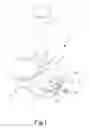
FIG. 1 is a perspective diagram showing a universal wheel according to an embodiment of the present invention.
FIG. 2 is a perspective break-down diagram showing the universal wheel of FIG. 1.
FIG. 3 is a perspective diagram showing the universal wheel of FIG. 1 applied to a cart.
FIG. 4 is a schematic diagram showing a first driving element of the universal wheel of FIG. 1 being driven.
FIG. 5 is a schematic diagram showing a second driving element of the universal wheel of FIG. 1 being driven.
FIG. 6 is another perspective diagram showing the universal wheel of FIG. 1.
FIG. 7 is a schematic diagram showing the universal wheel of FIG. 1 applied to a vehicle.
DETAILED DESCRIPTION OF THE PREFERRED EMBODIMENTS
The following descriptions are exemplary embodiments only, and are not intended to limit the scope, applicability or configuration of the invention in any way. Rather, the following description provides a convenient illustration for implementing exemplary embodiments of the invention. Various changes to the described embodiments may be made in the function and arrangement of the elements described without departing from the scope of the invention as set forth in the appended claims.
As shown in FIGS. 1 and 2, a universal wheel 1 according to an embodiment of the present invention includes a vertical axle 2, a base member 3, a telescoping and adjustable lift member 9, and at least a wheel member 5. A first end of the vertical axle 2 is joined to a bottom end of the lift member 9, and a second end of the vertical axle 2 is joined to the base member 3. The lift member 9 adjusts a height of the universal wheel 1 from the ground.
A bearing 31 is laid on a top side of the base member 3 and beneath the bottom end of the lift member 9. The vertical axle 2 runs vertically upward through a fastening element 4, the top side of the base member 3, and the bearing 31. The second end of the vertical axle 2 has flange segments 21 for engaging with the fastening element 4.
The base member 3 has a pair of downward extended and parallel side pieces (not numbered) between which the wheel member 5 is rotatably joined by a lateral axle of the wheel member 5. A first driving element 6 is configured on the base member 3 engaging the bottom end of the lift member so as to turn the base member 3 and therefore the wheel member 5 laterally within 360 degrees around the vertical axle 2 smoothly with the help of the bearing 31. Due to the bearing 31, the vertical axle 2 and the lift member 9 do not turn along with the base member 3 and the wheel member 5. The lateral axle of the wheel member 5 is coupled to a second driving element 7 configured on a first side piece. The second driving element 7 engages the lateral axle of the wheel member 5 so that the wheel member 5 rolls around the lateral axle. A tubular element 32 coupled to the lateral axle of the wheel member 5 is configured on a second side piece. The tubular element 32 has a number of ribs 33 around an inner wall of the tubular element 32. An external shaft A may engages the tubular element 32 through the ribs 33 to roll the wheel member 5.
An engaging element 34 is configured on the tubular element 32 for coupling and decoupling the external shaft A with the tubular element 32. When the engaging element 34 decouples the external shaft A with the tubular element 32, the base member 3 along with the wheel member 5 may be turned laterally within 360 degrees by the first driving element 6, or the wheel member 5 may be rolled by the second driving element 7. When the engaging element 34 couples the external shaft A with the tubular element 32, the wheel member 5 may be rolled by the external shaft A. In the present embodiment, the engaging element is a hydraulic device.
As shown in FIGS. 3 to 5, the lift member 9 has a top end fixedly joined to a bottom side of a platform 8 of a cart so that the universal wheel 1 is configured beneath the platform 8. The platform 8's height from the ground therefore may be adjusted through the lift member 9. To move the cart around, the first driving element 6 may turn the base member 6 as well as the wheel member 5 laterally for 360 degrees so as to change the cart's moving direction. Then the second driving element 7 may rolls the wheel member 5 forward or backward so as to move the cart. As such, the universal wheel 1 can be rolled forward, laterally, obliquely, turned 360 degrees when standing in place, or in a combination of these operations. The first and second driving elements 6 and 7 are motors in the present embodiment.
As shown in FIG. 6, the first and second driving elements 6 and 7, and the engaging element 34 may be controlled remotely, automatically, or manually.
As shown in FIG. 7, the universal wheel 1 is joined to a bottom side of a vehicle's chassis B which also includes at least one external shaft A and a motor C. When the motor C is started, the external shaft A is coupled to the tubular element 32 by the engaging element 34, the motor C drives the external shaft A as well as the wheel member 5 to roll, and therefore the vehicle is moved. After decoupling the external shaft A with the tubular element 32 by the engaging element 34, the base member 3 as well as the wheel member 5 may be turned laterally for 360 degrees. Even when the motor C cannot be started, the wheel member 5 can still be rolled by the second driving element 7. In this way, when the motor C fails, a driver of the vehicle does not need to manually push the vehicle around.
While certain novel features of this invention have been shown and described and are pointed out in the annexed claim, it is not intended to be limited to the details above, since it will be understood that various omissions, modifications, substitutions and changes in the forms and details of the device illustrated and in its operation can be made by those skilled in the art without departing in any way from the claims of the present invention.
Claims
I claim:1. A universal wheel, comprising
a base member having a top side, a pair of downward extended and parallel side pieces from the top side, and a bearing on the top side;
a lift member having a bottom end joined to the top side of the base member on the bearing for adjusting a height of the wheel member from the ground;
a vertical axle running vertically upward through a fastening element, the top side of the base member, and the bearing, where a first end of the vertical axle is joined to the bottom end of the lift member, a second end of the vertical axle has flange segments for engaging with the fastening element;
a wheel member having a lateral axle whose two ends are joined to the side pieces, respectively, so that the wheel member is rotatable between the side pieces around the lateral axle;
a first driving element for engaging the bottom end of the lift member and therefore turning the base member laterally within 360 degrees around the vertical axle;
a second driving element coupled to the lateral axle of the wheel member for rolling the wheel member around the lateral axle; and
a tubular element configured on a second side piece and coupled to the lateral axle of the wheel member, where the tubular element has a plurality of ribs around an inner wall of the tubular element for detachably engaging an external shaft;
wherein the vertical axle and the lift member do not laterally turn along with the base member due to the bearing.
2. The universal wheel according to claim 1, wherein the first driving element is configured on the base member.
3. The universal wheel according to claim 2, wherein the first driving element is a motor.
4. The universal wheel according to claim 1, wherein the second driving element is configured on a first side piece of the base member.
5. The universal wheel according to claim 4, wherein the second driving element is a motor.
6. The universal wheel according to claim 1, further comprising an engaging element configured on the tubular element for coupling and decoupling the external shaft with the tubular element.
7. The universal wheel according to claim 6, wherein the engaging element is a hydraulic device.
Images & Drawings included:


Sources:
- United States Patent and Trademark Office - verify current appl. status at the USPTO↗
Similar patent applications:
- » 20220332141
Welding shaft and wheel assembly for universal wheel, and universal wheel - » 20130186723
Universal wheeled bag system - » 10807877
Universal wheel locking system - » 20060220333
Universal wheeled assembly for gas and electric line trimmers - » 11069092
Universal wheel pylon - » 20060125309
Universal wheel - » 20110215637
Universal wheel hub - » 20100038878
Universal wheel seat - » 17895577
Universal wheel driving system - » 20120267208
Universal wheeled bag system
Recent applications in this class:
- » 20250289302 2025-09-18
Power Train for a Motor Vehicle - » 20250269712 2025-08-28
ELECTRIC AXLE ASSEMBLY - » 20250269711 2025-08-28
ELECTRIC AXLE ASSEMBLY - » 20250256561 2025-08-14
Modular systems for electric wheel assemblies - » 20250214411 2025-07-03
IN-WHEEL DRIVE ASSEMBLY - » 20250196616 2025-06-19
MODULAR AND INTEGRATED ELECTRIC VEHICLE DRIVING AND STEERING SYSTEM - » 20250196615 2025-06-19
DRIVING MODULE FOR VEHICLE AND POWER SUPPLY STRUCTURE - » 20250196614 2025-06-19
WHEEL ASSEMBLY AND A VEHICLE INCLUDING THE SAME - » 20250196613 2025-06-19
AXLE ASSEMBLY HAVING AN ELECTRIC MOTOR - » 20250196612 2025-06-19
MOTOR SYSTEM WITH STATOR WINDINGS CONNECTED TO MULTIPLE DRIVES