Framed modular ballast block and method of construction
US20180128417A1
2018-05-10
15/801,592
2017-11-02
✅ Patent granted
US 10,439,547 B2
2019-10-08
-
-
Eret C McNichols
Stuart M. Goldstein
2038-01-20
Abstract:
A ballast block has a uniquely designed framework consisting of lightweight, pre-fabricated, metal panel members and cross-bracing and elongated bracing members. The various components of the ballast block framework are compactly bundled and shipped to the end use location for assembly on-site. Once assembled, the ballast block framework is properly positioned on its permanent, end use location and concrete or equivalent ballast material is poured into the framework, completely filling its internal space. The ballast block can be sized and fabricated for the specific desired purpose.
Applicant:
Interested in similar patents?
Get notified when new applications in this technology area are published.
Classification:
E04H12/2246 » CPC further
Towers; Masts or poles; Chimney stacks; Water-towers; Methods of erecting such structures; Sockets or holders for poles or posts to be placed on the ground filled with water, sand or the like
E04H12/2253 » CPC further
Towers; Masts or poles; Chimney stacks; Water-towers; Methods of erecting such structures; Sockets or holders for poles or posts Mounting poles or posts to the holder
E04H12/22 IPC
Towers; Masts or poles; Chimney stacks; Water-towers; Methods of erecting such structures Sockets or holders for poles or posts
F16M11/20 » CPC main
Stands or trestles as supports for apparatus or articles placed thereon Stands for scientific apparatus such as gravitational force meters Undercarriages with or without wheels
F16M11/16 » CPC further
Stands or trestles as supports for apparatus or articles placed thereon Stands for scientific apparatus such as gravitational force meters; Heads Details concerning attachment of head-supporting legs, with or without actuation of locking members thereof
E02D27/08 » CPC further
Foundations as substructures; Flat foundations Reinforcements for flat foundations
E04G9/08 » CPC further
Forming or shuttering elements for general use Forming boards or similar elements, which are collapsible, foldable, or able to be rolled up
E02D27/00 » CPC further
Foundations as substructures
E04G9/02 IPC
Forming or shuttering elements for general use Forming boards or similar elements
E04G9/083 » CPC further
Forming or shuttering elements for general use; Forming boards or similar elements, which are collapsible, foldable, or able to be rolled up which are foldable
E04G13/02 » CPC further
Falsework, forms, or shutterings for particular parts of buildings, e.g. stairs, steps, cornices, balconies foundations, sills for columns or like pillars; Special tying or clamping means therefor
E02D27/42 » CPC further
Foundations as substructures; Foundations for special purposes Foundations for poles, masts or chimneys
E04G2009/028 » CPC further
Forming or shuttering elements for general use; Forming boards or similar elements with reinforcing ribs on the underside
E04G9/06 » CPC further
Forming or shuttering elements for general use; Forming boards or similar elements the form surface being of metal
H02S20/10 » CPC further
Supporting structures for PV modules Supporting structures directly fixed to the ground
E02D27/30 » CPC further
Foundations as substructures Foundations made with permanent use of sheet pile bulkheads, walls of planks, or sheet piling boxes
F16M2200/08 » CPC further
Details of stands or supports Foot or support base
H02S20/20 » CPC main
Supporting structures for PV modules Supporting structures directly fixed to an immovable object
H02S20/00 » CPC further
Supporting structures for PV modules
Description
RELATED APPLICATION
This application claims the benefit of provisional application 62/418,931 filed on Nov. 8, 2016.
BACKGROUND OF THE INVENTION
Ballast blocks and similar anchoring and building blocks are commonly used for a variety of structures and purposes. One such important use of ballast blocks are as foundational mounts to support solar panels and their supporting systems. There is currently no ballast block member or means of fabricating a ballast block which accomplishes this need and which also is relatively easy to construct and has the versatility of selective placement at the end use location.
SUMMARY OF THE INVENTION
Specifically, the present invention relates to the design and construction of framed ballast blocks for anchoring upstanding structures, e.g. solar racking and communication towers, against meteorological and geological events. Such ballast blocks can also be used for highway barricades, protection against beach erosion, building foundations, boat and ship docks, and other applications which require high strength, stable ballast supports or protective structures.
The ballast block of the present invention comprises a uniquely designed framework consisting of lightweight, pre-fabricated, metal panel members and cross-bracing and elongated bracing members. The various components of the ballast block framework are compactly bundled and shipped to the end use location for assembly on-site. Once assembled, the ballast block framework is properly positioned on its permanent, end use location and concrete or equivalent ballast material is poured into the framework, completely filling its internal space. The ballast block can be sized and fabricated for the specific desired purpose.
The ballast block of the present invention provides a low cost, lightweight framing structure which is conveniently and easily shipped, located, and assembled right at the end use site. Once set in place and filled with concrete or other heavy ballast material, it provides a stable and effective foundation.
The novel features which are considered as characteristic of the invention are set forth in particular in the appended claims. The invention, itself, however, both as to its design, construction and use, together with additional features and advantages thereof, are best understood upon review of the following detailed description with reference to the accompanying drawings.
BRIEF DESCRIPTION OF THE DRAWINGS
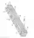
FIG. 1 is an isometric view of the stacked and secured bundle of ballast block framework components of the present invention.
FIG. 2 is an exploded view of the ballast block framework components of the present invention.
FIG. 3 is a view of the assembled ballast block framework of the present invention,
FIG. 4 illustrates the filling of the ballast block framework of the present invention with ballast material.
FIGS. 5-8 illustrate various embodiments of the tab member connector of the present invention.
FIG. 9 illustrates the use of the ballast block of the present invention supporting a solar panel system.
DETAILED DESCRIPTION OF THE INVENTION
Ballast block 1 of the present invention comprises framework 2 having first panel member 4 and second panel member 14. First panel ember 4 comprises sidewall section 6 extending the length of framework 2 of ballast block 1, first end wall section 8, and second end wall section 10. End wall sections 8 and 10 are connected by perforated hinges 12 and 13 to sidewall section 6 and are folded inward at the hinges so that they are positioned at a 90° angle to the sidewall section. In like manner, second panel member 14 comprises sidewall section 16 extending the length of framework 2 of ballast block 1, first end wall section 18, and second end wall section 20. End wall sections 18 and 20 are connected by perforated hinges 22 and 23 to sidewall section 16 and are folded inward at the hinges so that they are positioned at a 90° angle to the sidewall section. To form framework 2, folded end wall section 8 is aligned with and is positioned to overlap end wall section 18 and folded end wall section 10 is aligned with and is positioned to overlap end wall section 20. The end wall sections are secured by screws or equivalent fasteners 9.
First panel member 4 and second panel member 14 are formed of relatively lightweight, heavy duty 12/14 gauge galvanize steel.
Cross-bracing members 26, 28, and 30 have tab member connectors 32, 33, 34, 35, 36 and 37 extending from the termini of the connectors, as best seen in FIG. 2. The tab member connectors are configured to be inserted into slots 42, 43, 44, 45, 46, and 47 in sidewall sections 6 and 16 in order to secure cross-bracing members 26, 28, and 30 between the sidewall sections, as best seen in FIG. 3.
It is contemplated that various types of tab member connectors can be used. For example, connectors 32, 33, 34, 35, 36, and 37, shown in FIGS. 2-5, are twist connectors. FIG. 6 shows tab member connector 48 extending from cross-bracing member 30a, as a flat plate which is configured to be folded against sidewall sections 6 and 16 and secured in place by a fastener. FIGS. 7 and 8 show tab member connectors 50 and 52 extending from cross-bracing members 30b and 30c, having slits 54 and 56 which are designed to be inserted straight into the metal of sidewall sections 6 and 16.
Elongated bracing member 60 is positioned over cross-bracing members 26, 28, and 30 and secured thereto by screws or equivalent fasteners 9. Bracing member 60 is provided, not only to provide added strength to framework 2, but also as a support member to facilitate construction of structures which are built on ballast block 1.
Framework 2 is filled with ballast material 70, such as concrete or landfill, to form completed ballast block 1. See FIG. 4.
A significant advantage of this invention resides in the manner in which it is designed to be transported and then constructed at its end use location. All the components of ballast block framework 2 are designed to be stacked, in a disassembled state, in a compact, easy to transport, secured bundle 80. FIG. 1 shows an example of how two ballast block frameworks can be packaged in bundle 80, with ballast block framework components such as panel members 4 and 14, cross-bracing members 26, 28, and 30, elongated bracing member 60, and fastener hardware container 82. Binding straps 84, 86, and 88 tightly secure the framework components within bundle 80.
Bundle 80 is transported to the end use location of ballast block 1, where the ballast block framework components are unfastened and separated from the bundle. The various framework components are then assembled into the framework configuration previously described and shown in FIGS. 2 and 3, to form completely formed ballast block framework 2.
Framework 2 is next transported to and positioned on its exact end use location, where it is filled with ballast material 70 to form ballast block 1, ready to be used.
FIG. 9 illustrates an example of how the ballast blocks of the invention are to be utilized. Ballast blocks 1a and 1b are positioned to support solar panel racking system 90 designed to rigidly and permanently support solar panels 100.
Certain novel features and components of this invention are disclosed in detail in order to make the invention clear in at least one form thereof. However, it is to be clearly understood that the invention as disclosed is not necessarily limited to the exact form and details as disclosed, since it is apparent that various modifications and changes may be made without departing from the spirit of the invention.
Claims
1. The method of constructing a ballast block at an end use location, said method comprising:
providing a secured bundle of stacked, disassembled ballast block framework components;
transporting the bundle of stacked, disassembled ballast block framework components to the end use location;
unfastening and separating the disassembled ballast block framework components from the secured bundle;
assembling the ballast block framework components to form the framework for the ballast block;
positioning the ballast block framework at the end use location; and
filling the ballast block framework with ballast material to immobilize the ballast block at the end use location.
2. The method as in claim 1 wherein the ballast block framework components comprise panel members, cross-bracing members, and an elongated bracing member.
3. The method as in claim 1 wherein the ballast material is concrete.
4. The method as in claim 1 wherein the ballast material is landfill.
5. A ballast block comprising:
a framework comprising:
a first panel member having a sidewall section extending the length of the ballast block and first and second end wall sections each end wall section positioned at an angle to the panel member;
a second panel member having a sidewall section extending the length of the ballast block and first and second end wall sections each end wall section positioned at an angle to the sidewall section;
cross-bracing members extending between the first and second panel members; and
an elongated bracing member positioned over and connected to the cross-bracing members; and
ballast material filling the framework between the first and second panel members.
6. The ballast block as in claim 5 wherein the end wall sections of the first and second panel members are attached to their respective panel members by foldable hinges.
7. The ballast block as in claim 5 wherein connectors extend from the termini of each of the cross-bracing members.
8. The ballast block as in claim 7 wherein the sidewall sections of the first and second panel members have slots therethrough into which the connectors are inserted, whereby upon insertion of the connectors into the slots, the cross-bracing members are secured to the panel members.
9. The ballast block as in claim 7 wherein the connectors are tab members.
10. The ballast block as in claim 8 wherein the connectors are tab members.
11. The ballast block as in claim 9 in which the tab members are twist connectors.
12. The ballast block as in claim 10 in which the tab members are twist connectors.
13. The ballast block as in claim 9 wherein the tab members comprise slits.
14. The ballast block as in claim 9 wherein the tab connectors are folded against the first and second side panels and are secured by fasteners.
15. The ballast block as in claim 1 wherein the ballast material is concrete.
16. The ballast block as in claim 1 wherein the ballast material is landfill.
17. The ballast block as in claim 1 wherein the end wall sections of the first and second panel members are positioned at an 90° angle to the side wall sections of the panel members.
Images & Drawings included:


Sources:
- United States Patent and Trademark Office - verify current appl. status at the USPTO↗
Recent applications in this class:
- » 20250084958 2025-03-13
Laptop Raiser Device - » 20240318769 2024-09-26
LEVELING PAD SYSTEM AND METHOD OF USE - » 20220228700 2022-07-21
Monitor riser with stow-away dry erase pad - » 20200072408 2020-03-05
Support stand for magnetic resonance imaging scanner - » 20200003358 2020-01-02
Safety Supporting Frame Device and Supporting Frame Assembly - » 20190331290 2019-10-31
Compressible support structures - » 20180216778 2018-08-02
Support frame and display assembly - » 20140252198 2014-09-11
SUPPORT STRUCTURE WITH DISSIMILAR METAL WELDS - » 20140175256 2014-06-26
METHOD FOR PREVENTING OVERTURN OF TRESTLE - » 20140166839 2014-06-19
ENCLOSURE SUPPORTER