Switchable bearing bushing for a motor vehicle
US20180149225A1
2018-05-31
15/579,628
2016-06-02
✅ Patent granted
US 10,451,132 B2
2019-10-22
WO; PCT/DE2016/200259; 20160602
WO; WO2016/198066; 20161215
Melanie Torres Williams
Antun M. Peakovic
2036-06-02
Abstract:
The disclosure relates to bearing bushes for a motor vehicle, in which the bearing bushing may be switchable between a first and a second stiffness stage.
The bearing bushing may include a first elastomer ring, which is arranged at least indirectly on an outer circumferential surface of a bolt, and a second elastomer ring, which is arranged radially between a first and second sleeve. The second sleeve may be arranged radially between the first and the second elastomer rings. In order to change the stiffness stage of the bearing bushing, the two sleeves may be connectable to one another by at least one ring which comes into contact with said sleeves at an end side.
Assignee:
- Schaeffler Technologies AG &Co. KG 4,023 🇩🇪 Herzogenaurach, Germany
- Schaeffler Technologies AG & Co. KG 3 🇩🇪 Herzogenaurzch, Germany
Applicant:
Interested in similar patents?
Get notified when new applications in this technology area are published.
Classification:
F16F1/3615 » CPC main
Springs made of rubber or other material having high internal friction, e.g. thermoplastic elastomers with means for modifying the spring characteristic
B60G7/001 » CPC further
Pivoted suspension arms; Accessories thereof Suspension arms, e.g. constructional features
B60G2204/10 » CPC further
Indexing codes related to suspensions or to auxiliary parts Mounting of suspension elements
F16F1/36 IPC
Springs made of rubber or other material having high internal friction, e.g. thermoplastic elastomers
B60G17/02 » CPC further
Resilient suspensions having means for adjusting the spring or vibration-damper characteristics, for regulating the distance between a supporting surface and a sprung part of vehicle or for locking suspension during use to meet varying vehicular or surface conditions, e.g. due to speed or load Spring characteristics, e.g. mechanical springs and mechanical adjusting means
B60G2204/41 » CPC further
Indexing codes related to suspensions or to auxiliary parts; Auxiliary suspension parts; Adjustment of suspensions Elastic mounts, e.g. bushings
F16F2228/066 » CPC further
Functional characteristics, e.g. variability, frequency-dependence; Stiffness Variable stiffness
B60G7/00 IPC
Pivoted suspension arms; Accessories thereof
Description
CROSS-REFERENCE TO RELATED APPLICATIONS
This application is the U.S. National Phase of PCT Appln. No. PCT/DE2016/200259 filed Jun. 2, 2016, which claims priority to DE 102015210766.3 filed Jun. 12, 2015, the entire disclosures of which are incorporated by reference herein.
TECHNICAL FIELD
The disclosure relates to a bearing bushing for a motor vehicle, wherein the bearing bushing is switchable between a first and a second stiffness stage.
BACKGROUND
The structure and the resulting operational data of bearing bushings that are used in a chassis of a motor vehicle may have an influence on the driving and steering characteristics of the motor vehicle. Relatively minor changes to a spring constant or stiffness of the bearing bushings can have considerable effects on the vehicle characteristics, such as for example the understeer or oversteer characteristics and chassis noises, vibrations and running harshness. Depending on the setting of the bearing bushing, the motor vehicle has a relatively “soft” or relatively “hard” running characteristic.
The generally known prior art has disclosed various bearing bushings in the chassis region of a motor vehicle. Firstly, purely mechanical bearing bushings or rubber bearings are known which have a defined stiffness. Furthermore, hydraulically damped chassis bushings with fixed or variable stiffness are known. Furthermore, bearings with magnetorheological liquids or magnetorheological elastomers are known, wherein the stiffness can be varied by means of a magnetic field.
For example, DE 696 22 141 T2 discloses a method for producing and using a suspension bushing with variable stiffness for controlling the relative movement between a suspension link in a motor vehicle and a frame component of the motor vehicle. The suspension bushing has a variable stiffness, which is realized by virtue of the fact that there is an enclosed magnetorheological elastomer or gel, the stiffness of which is variably adjustable over a wide range, specifically by means of a controllable magnetic field. The variable controllable magnetic field is generated by means of an electromagnetic structure which is completely integrated, as part of the structure, into a suspension bushing structure.
SUMMARY
One problem addressed by the disclosure includes providing a particularly inexpensive bearing bushing, which is optimized from a manufacturing aspect, for a motor vehicle, the stiffness of which bearing bushing is mechanically adjustable and is thus not based on a hydraulic or magnetorheological operating principle.
According to an embodiment of the disclosure, the bearing bushing has a first elastomer ring, which is arranged at least indirectly on an outer circumferential surface of a bolt, and a second elastomer ring, which is arranged radially between a first and second sleeve, wherein the second sleeve is arranged radially between the first and the second elastomer ring, and wherein, in order to change the stiffness stage of the bearing bushing, the two sleeves are connectable to one another by means of a respective ring which comes into contact with said sleeves at an end side. In other words, a change between a first and a second stiffness stage occurs by virtue of the fact that the respective ring comes into contact with the respective sleeve at an end side and thereby bridges the second elastomer ring arranged radially therebetween. Spacing the two rings axially apart from the respective end face results, owing to a series connection of the two elastomer rings arranged radially with respect to one another, in a relatively soft stiffness of the bearing bushing.
A third sleeve may be arranged rotationally fixedly on the outer circumferential surface of the bolt. Consequently, the first elastomer ring makes radial contact with an outer circumferential surface of the third sleeve, wherein the third sleeve is supported on the outer circumferential surface of the bolt.
The first sleeve may be arranged rotationally fixedly in a housing bore. In particular, the housing bore is formed in a chassis component of a motor vehicle.
The respective ring is advantageously axially displaceable by means of an actuator arranged thereon. Here, it is also conceivable for a single actuator to act on both rings in order to displace these axially.
The disclosure encompasses the technical teaching whereby the housing bore has a respective guide element for the axial guidance of the respective ring. The respective guide element may for example be a friction-minimizing surface within the housing bore, which permits axial guidance of the respective ring. It is however furthermore also conceivable for a groove to be formed in the housing bore, which groove prevents a rotation of the respective ring relative to the housing bore.
Furthermore, the first and second sleeves preferably each have, on the end sides, a respective structure for axially receiving the respective ring. The respective structure is advantageously formed as a bevel. An axial toothing is however likewise possible.
The respective ring preferably has, on the end sides, a respective structure which is of complementary form with respect to the respective structure on the first and second sleeves. In other words, the respective structure on the respective rings may be formed as a bevel or as an axial toothing.
In one embodiment, the two rings and the three sleeves are produced from a metallic material or a polymer material.
BRIEF DESCRIPTION OF THE DRAWINGS
Further measures which improve the disclosure will be presented in more detail below together with the description of a preferred exemplary embodiment of the disclosure on the basis of the figures. In the figures:
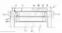
FIG. 1 is a perspective illustration of a bearing bushing according to the disclosure, which is provided for a chassis component of a motor vehicle,
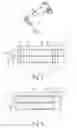
FIG. 2 shows a detail of a schematic sectional illustration for illustrating the structure of the bearing bushing according to the disclosure in the case of a first stiffness stage, and
FIG. 3 shows a detail of a schematic sectional illustration for illustrating the structure of the bearing bushing according to the disclosure as per FIG. 2 in the case of a second stiffness stage.
DETAILED DESCRIPTION
As per FIG. 1, a bearing bushing 1 according to the disclosure is arranged in a housing bore 6, provided for the purpose, of a chassis component 11. The chassis component 11 is installed in a chassis (not illustrated here) of a motor vehicle (not illustrated here). A further chassis component (not illustrated here) may for example be fastened to a bolt 2 of the bearing bushing 1.
FIGS. 2 and 3 show a partially illustrated switchable bearing bushing 1 according to the disclosure, which is switchable between a first and a second stiffness stage, wherein FIG. 2 illustrates a relatively soft stiffness stage and FIG. 3 illustrates a relatively hard stiffness stage of the switchable bearing bushing 1.
The bearing bushing 1 comprises a first and a second elastomer ring 3a, 3b and a first and a second sleeve 4a, 4b. Furthermore, the bearing bushing 1 has the bolt 2, on the outer circumferential surface of which a third sleeve 4c is rotationally fixedly arranged. The first elastomer ring 3a makes radial contact with the third sleeve 4c. The second elastomer ring 3b is arranged radially between the first and the second sleeve 4a, 4b, wherein the second sleeve 4b is arranged radially between the first and the second elastomer ring 3a, 3b and thus spatially separates the two elastomer rings 3a, 3b from one another. The first sleeve 4a is arranged rotationally fixedly in the housing bore 6.
Furthermore, the bearing bushing 1 comprises two rings 5a, 5b which are displaceable axially, by means of a respective actuator 7a, 7b arranged thereon, in order to in each case come into contact with the first and the second sleeve 4a, 4b at the end sides. The housing bore 6 has an integrated guide element 8 for the axial guidance of the respective ring 5a, 5b in the housing bore 6.
The first sleeve 4a has, on the end sides, a structure 9a which is provided for axially receiving the respective ring 5a, 5b. Furthermore, the second sleeve 4b also has, on the end sides, a structure 9b which is provided for axially receiving the respective ring 5a, 5b. The respective structure 9a, 9b on the respective ring 5a, 5b is in the form of a bevel. Furthermore, the respective ring 5a, 5b has, on the end sides, a respective structure 10 which is of complementary form with respect to the respective structure 9a, 9b on the respective first and second sleeves 4a, 4b.
In FIG. 2, the spacing between the two rings 5a, 5b is at a maximum, wherein the two elastomer rings 3a, 3b are situated in the force path and can be loaded by an external force that can be introduced via the bolt 2. The stiffness stage of the bearing bushing 1 is relatively soft owing to the two elastomer rings 3a, 3b arranged in series.
By contrast, the bearing bushing 1 as per FIG. 3 has a relatively hard stiffness stage. The spacing between the two rings 5a, 5b is at a minimum, whereby the two rings 5a, 5b come into contact with the first and the second sleeve 4a, 4b at the end sides and thereby relieve the second elastomer ring 3b of load. Consequently, the second elastomer ring 3b is bridged by the two rings 5a, 5b. Thus, only the first elastomer ring 3a would be loaded by an external force that can be introduced via the bolt 2.
LIST OF REFERENCE DESIGNATIONS
-
- 1 Bearing bushing
- 2 Bolt
- 3a, 3b Elastomer ring
- 4a-4c Sleeve
- 5a, 5b Ring
- 6 Housing bore
- 7a, 7b Actuator
- 8 Guide element
- 9a, 9b Structure
- 10 Structure
- 11 Chassis component
Claims
1. A bearing bushing for a motor vehicle, comprising:
a first elastomer, which is arranged at least indirectly on an outer circumferential surface of a bolt, and a second elastomer ring, which is arranged radially between a first and second sleeve, wherein the second sleeve is arranged radially between the first and the second elastomer ring; and
the bearing bushing being switchable between a first and a second stiffness stage, wherein in order to change the stiffness stage of the bearing bushing, the two sleeves are connectable to one another by a ring which comes into contact with said sleeves at an end side.
2. The bearing bushing as claimed in claim 1, wherein a third sleeve is arranged rotationally fixedly on the outer circumferential surface of the bolt.
3. The bearing bushing as claimed in claim 1, wherein the first sleeve is arranged rotationally fixedly in a housing bore.
4. The bearing bushing as claimed in claim 1, wherein the ring is axially displaceable by an actuator arranged thereon.
5. The bearing bushing as claimed in claim 3, wherein the housing bore has a guide element for axial guidance of the ring.
6. The bearing bushing as claimed in claim 1, wherein the first and second sleeves each have, on the end side, a respective structure for axially receiving the ring.
7. The bearing bushing as claimed in claim 6, wherein the ring has, on the end side, a respective structure which is of complementary form with respect to the respective structure on the first and second sleeves.
8. The bearing bushing as claimed in claim 2, wherein the ring and the three sleeves are produced from a metallic material or a polymer material.
9. The bearing bushing as claimed in claim 1, wherein there are two rings, each ring configured to come into contact with said sleeves at opposing end sides.
10. The bearing bushing as claimed in claim 9, wherein the first and second sleeves each have, on each end side, a structure for axially receiving the two rings; and
the two rings have, on each end side, a respective structure which is of complementary form with respect to the structure on the first and second sleeves.
11. A bearing bushing for a motor vehicle, comprising:
a first elastomer ring, which is arranged at least indirectly on an outer circumferential surface of a bolt, and a second elastomer ring, which is arranged radially between a first and second sleeve, wherein the second sleeve is arranged radially between the first and the second elastomer ring; and
the bearing bushing being switchable between a first and a second stiffness stage, wherein in order to change the stiffness stage of the bearing bushing, the first and second sleeves are connectable to one another by a first axial ring and a second axial ring, which are configured to come into contact with said first and second sleeves at opposing end sides thereof.
12. The bearing bushing as claimed in claim 11, wherein a third sleeve is arranged rotationally fixedly on the outer circumferential surface of the bolt.
13. The bearing bushing as claimed in claim 12, wherein the two axial rings and the three sleeves are produced from a metallic material or a polymer material.
14. The bearing bushing as claimed in claim 11, wherein the first sleeve is arranged rotationally fixedly in a housing bore.
15. The bearing bushing as claimed in claim 14, wherein the housing bore has a guide element for axial guidance of the first and second axial rings.
16. The bearing bushing as claimed in claim 11, wherein the first and second axial rings are axially displaceable by an actuator arranged thereon.
17. The bearing bushing as claimed in claim 11, wherein the first and second sleeves each have, on the end side, a respective structure for axially receiving the first and second axial rings.
18. The bearing bushing as claimed in claim 17, wherein the first and second axial rings have, on an end side, a respective structure which is of complementary form with respect to the respective structure on the first and second sleeves.
Images & Drawings included:
Sources:
- United States Patent and Trademark Office - verify current appl. status at the USPTO↗
Similar patent applications:
- » 20180050574
Switchable bearing bush for a motor vehicle - » 20180163807
Switchable bearing bushing for a motor vehicle - » 20180209478
Switchable bearing bush for a motor vehicle - » 20180223936
Switchable bearing bush for a motor vehicle - » 20180223937
Switchable bearing bushing for a motor vehicle
Recent applications in this class:
- » 20230243397 2023-08-03
Equipment platform - » 20220325768 2022-10-13
ZERO POISSON'S RATIO STRUCTURE AND A PLANAR STRUCTURE OF ZERO POISSON'S RATIO IN WHICH THE STRUCTURE IS MATRIXED IN A PLANE - » 20210404527 2021-12-30
Equipment platform - » 20200355235 2020-11-12
Equipment platform - » 20200102994 2020-04-02
Equipment platform - » 20180195572 2018-07-12
Variable rate bound stoppers and variable rate suspension systems containing variable rate bound stoppers - » 20170328433 2017-11-16
Active vibration controller - » 20170167558 2017-06-15
Mount assembly and method of adjusting stiffness - » 20150292589 2015-10-15
SWITCHABLE/VARIABLE RATE ISOLATORS USING SHAPE MEMORY ALLOYS - » 20150176671 2015-06-25
Elastomer components that can be pre-stressed by pressure means, and method for the production thereof
Recent applications for this Assignee:
- » 20250293624 2025-09-18
METHOD FOR DETERMINING AN INITIAL ROTOR POSITION OF A ROTOR, COMPUTER PROGRAM PRODUCT, CONTROL UNIT, ELECTRIC MACHINE, INSPECTION AND/OR TEST METHOD AND TEST STAND - » 20250290560 2025-09-18
TORQUE CONVERTER WITH PULLING BIAS SPRING - » 20250283516 2025-09-11
FREEWHEEL DEVICE AND FREEWHEEL CLUTCH - » 20250279708 2025-09-04
HYBRID DRIVE RESOLVER ROTOR MOUNTING ARRANGEMENT - » 20250273375 2025-08-28
DETENT SOLENOID - » 20250269726 2025-08-28
Electrical Circuit, On-Board Power Supply System, Vehicle, Method, Computer Program, And Computer-Readable Medium - » 20250269694 2025-08-28
ADJUSTMENT MECHANISM COMPRISING A LINEAR ACTUATOR, VEHICLE AND METHOD FOR OPERATING A VEHICLE - » 20250264157 2025-08-21
PLANETARY GEARBOX HAVING A ROTATIONALLY FIXED THRUST WASHER OF THE PLANET BEARING - » 20250263129 2025-08-21
WHEEL WELL GUARD FOR A WHEEL WELL OF A VEHICLE AND VEHICLE HAVING THE WHEEL WELL GUARD - » 20250262941 2025-08-21
Individual Monitoring Of A Plurality Of Output Points Of A System For The Vehicle-Based Supply Of External Loads