Method for operating an automatic transmission control
US20180149264A1
2018-05-31
15/806,617
2017-11-08
✅ Patent granted
US 10,267,413 B2
2019-04-23
-
-
David J Hlavka
Davis & Bujold PLLC | Michael J. Bujold
2037-11-08
Abstract:
A method of operating an automated transmission control for a powershift transmission having a plurality of powershift gears and a synchronized transmission having a plurality of synchronized gears in the drive-train of a vehicle. The drive-train includes a drive motor, the powershift transmission and the synchronized transmission, with an electronic control unit by which an upshift of the gears of the synchronized transmission and the upshift of the gears of the powershift transmission can be carried out, and to which a motor load signal representing the motor load of the drive motor and a rotational speed signal representing the rotational speed at the output of the drive motor can be sent.
Assignee:
- ZF FRIEDRICHSHAFEN AG 3,767 🇩🇪 Friedrichshafen, Germany
Applicant:
Interested in similar patents?
Get notified when new applications in this technology area are published.
Classification:
F16H61/0213 » CPC main
Control functions within change-speed- or reversing-gearings for conveying rotary motion characterised by the signals used the signals being electric for gearshift control, e.g. control functions for performing shifting or generation of shift signal characterised by the method for generating shift signals
F16H2059/366 » CPC further
Control inputs to control units of change-speed-, or reversing-gearings for conveying rotary motion; Inputs being a function of speed Engine or motor speed
F16H61/02 IPC
Control functions within change-speed- or reversing-gearings for conveying rotary motion characterised by the signals used
F16H2061/0216 » CPC further
Control functions within change-speed- or reversing-gearings for conveying rotary motion characterised by the signals used the signals being electric for gearshift control, e.g. control functions for performing shifting or generation of shift signal characterised by the method for generating shift signals Calculation or estimation of post shift values for different gear ratios, e.g. by using engine performance tables
F16H59/48 » CPC further
Control inputs to control units of change-speed-, or reversing-gearings for conveying rotary motion Inputs being a function of acceleration
F16H59/36 » CPC further
Control inputs to control units of change-speed-, or reversing-gearings for conveying rotary motion Inputs being a function of speed
Description
This application claims priority from German patent application serial no. 10 2016 223 569.9 filed Nov. 29, 2016.
FIELD OF THE INVENTION
The invention relates to a method for operating an automated transmission control for a powershift transmission comprising a plurality of powershiftable gears and a synchronized transmission comprising a plurality of synchronized gears in a drive-train of a vehicle, such that the drive-train comprises a drive motor, the powershift transmission and the synchronized transmission, with an electronic control unit by means of which an upshift of the gears of the synchronized transmission and of the gears of the powershift transmission can be carried out and to which a motor bad signal representing the motor load of the drive motor and a rotational speed signal representing the rotational speed of the output of the drive motor can be supplied.
BACKGROUND OF THE INVENTION
In a method for operating an automated transmission control, it is known first to shift each powershift gear in an engaged synchronized gear, before the synchronized gear can be changed. The result of this is that many powershift gears have to be engaged and the vehicle accelerates relatively slowly, with poor efficiency.
SUMMARY OF THE INVENTION
Thus, the purpose of the present invention is to provide a method for operating an automated transmission control of the type mentioned, which at least substantially reduces these disadvantages, improves efficiency and enables the vehicle to accelerate more rapidly.
According to the invention, these objectives are achieved in that the synchronized transmission:
-
- if a predetermined rotational speed rise/rotational speed gradient of the rotational speed of the output of the drive motor is exceeded, or
- if a predetermined rotational speed of the output of the drive motor is exceeded and a motor load increases above a predetermined motor load which is lower than the full motor load,
- can be upshifted by one or more synchronized gears,
- and the powershift transmission:
- below a predetermined rotational speed rise/rotational speed gradient of the rotational speed of the output of the drive motor, or
- below a predetermined rotational speed of the output of the drive motor and a motor load below a predetermined motor load, and if a predeterminable rotational speed threshold of the rotational speed of the output of the drive motor is reached, can be upshifted by one or more powershift gears.
By virtue of this method, it is decided on the basis of the motor load whether a gear of the synchronized transmission or whether all the gears of the powershift transmission have to be shifted. In that way, depending on the motor load the gears of the synchronized transmission can be engaged directly, whereby the vehicle can accelerate more rapidly and not all of the gears of the powershift transmission have to be shifted.
In the automatic mode of the vehicle, the electronic control unit checks the motor load of the drive motor, the rotational speed at the output of the drive motor and the gradient of the rotational speed of the drive motor before an automated shift, and decides whether a gear of the synchronized transmission or whether all the gears of the powershift transmission should be shifted. If the motor load is high, then for the next automated shift, a gear of the powershift transmission is shifted, since a gearshift of the synchronized transmission would result in too high a load on the drive motor. If the motor load is low, a gearshift is carried out in the synchronized transmission since the drive motor is not yet loaded to its limit and still has reserves in the next gear of the synchronized transmission.
The predetermined rotational speed at the output of the drive motor is preferably higher than 1900 r/min and particularly in the range above 2050 r/min.
The predetermined motor load is preferably higher than 65% of the full load, in particular in the range of 75% of the full load.
The predeterminable rotational speed threshold of the rotational speed of the output of the drive motor can be more than 1300 r/min and is preferably between 1400 r/min and 2100 r/min.
To vary the rotational speed threshold the predeterminable rotational speed threshold can be manually input to the control unit, for which purpose, in particular the predeterminable rotational speed threshold can be input intto the control unit by way of an input unit.
It is understood that these values depend on the type of drive motor and can differ from the values mentioned.
BRIEF DESCRIPTION OF THE DRAWINGS
An example embodiment of the invention is illustrated in the drawings and will be described in greater detail below. The drawings show:
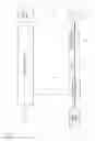
FIG. 1: A block diagram of an automated transmission control for a powershift transmission having a plurality of powershift gears and a synchronized transmission having a plurality of synchronized gears, in the drive-train of a vehicle
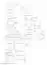
FIG. 2: A flow chart of a method for operating an automated transmission control according to FIG. 1 for a powershift transmission having a plurality of powershift gears and a synchronized transmission having a plurality of synchronized gears, in the drive-train of a vehicle.
DETAILED DESCRIPTION OF THE PREFERRED EMBODIMENTS
The automated transmission control illustrated in FIG. 1 comprises a drive motor 1 of a vehicle, by means of which a powershift transmission 2 can be driven in rotation. By way of a driving clutch 3, the powershift transmission 2 drives a synchronized transmission 4, which in turn rotationally drives the rear axle 12 of the vehicle.
The powershift transmission 2 has gears 1, 2, 3, 4, 5 and 6. The synchronized transmission 4 has gears A, B, C, D and E.
By way of a first signal line 5, a motor load signal representing the motor load of the drive motor 1 is sent to an electronic control, unit 6.
By way of a second signal line 7, the control unit 6 receives rotational speed signals representing the rotational speed at the output of the drive motor 1.
For the input of a rotational speed threshold of the rotational speed at the output of the drive motor 1, an input unit 10 is provided, from which an input line 11 leads to the control unit 6.
In accordance with the evaluation of the signals received by way of the signal lines 5 and 7 and via the input line 11, the control unit 6 actuates the powershift transmission 2, via the first control line 8, to shift a powershift gear or the synchronized transmission 4, via the second control line 9, to shift a synchronized gear.
The flow chart represented in FIG. 2 shows the method for operating the automated transmission control according to FIG. 1, when by virtue of the motor load a gear of the synchronized transmission 4 or a gear of the powershift transmission 2 has to be engaged, respectively.
In a first step 13, the vehicle is started in the synchronized gear “A” and the powershift gear “1”.
In the second step 14, it is decided whether the conditions for an automated shift of the synchronized transmission 4 are fulfilled.
If at the output 15 it is found that such is not the case, then in the third step 16 the powershift transmission 2 is shifted from powershift gear “1” to powershift gear “2”, whereas the synchronized gear “A” is left unchanged,
In the fourth step 17, a decision is again made whether the conditions for an automated shift of the synchronized transmission 4 are fulfilled.
If at the output 18 it is found that such is not the case, then in the fifth step 19 the powershift transmission 2 is shifted from powershift gear “2” to powershift gear “3”, whereas the synchronized gear “A” is left unchanged.
Subsequently, when by virtue of the motor load a gear of the synchronized transmission 4 or a gear of the powershift transmission 2 is to be changed, a decision process as above takes place.
If by virtue of the motor load, no gear of the synchronized transmission 4 and no gear of the powershift transmission 2 have to be changed, then the powershift transmission 2 and the synchronized transmission 4 are left in their initial gears.
If at the output 20 of the fourth step 17, it is found that the conditions for an automated shift in the synchronized transmission 4 are fulfilled, then in the sixth step 21 a shift takes place in the synchronized transmission 4 into the synchronized gear “B” and in the powershift transmission 2 into the powershift gear “1”
If by virtue of the motor load no gear of the synchronized transmission 4 and no gear of the powershift transmission 2 have to be changed, then after step 21 the powershift transmission 2 and the synchronized transmission 4 are left in their current gears.
If at the output of the second step 14 it is found that the conditions for an automated shift of the synchronized transmission 4 are fulfilled, then in the seventh step 23 a shift takes place in the synchronized transmission 4 into the synchronized gear “B” and in the powershift transmission 2 into the powershift gear “1”.
In the eighth step 24 it is again decided whether the conditions for an automated shift of the synchronized transmission 4 are fulfilled.
If at the output 25, it is found that such is not the case, then in step 26 the powershift transmission 2 is shifted from powershift gear “1” to powershift gear “2”, whereas the synchronized gear “B” is left unchanged.
If by virtue of the motor load no gear of the synchronized transmission 4 and no gear of the powershift transmission 2 have to be changed, then after step 26 the powershift transmission 2 and the synchronized transmission 4 are left in their current gears.
If at the output 27 of the eighth step 24 it is found that the conditions for an automated shift in the synchronized transmission 4 are fulfilled, then in the tenth step 28 the synchronized transmission 4 is shifted into the synchronized gear “C” and the powershift transmission 2 is shifted to the powershift gear “1”.
In the eleventh step 29 it is again decided whether the conditions for an automated shift in the synchronized transmission 4 are fulfilled.
If at the output 30 it is found that such is not the case, then in the twelfth step 31 the powershift transmission 2 is shifted from powershift gear “1” into powershift gear “2”, whereas the synchronized gear “C” is left unchanged.
If by virtue of the motor load no gear of the synchronized transmission 4 and no gear of the powershift transmission 2 have to be changed, then after step 31 the powershift transmission 2 and the synchronized transmission 4 are left in their current gears.
If at the output 32 of the eighth step 24 it is found that the conditions for an automated shift in the synchronized transmission 4 are fulfilled, then in the thirteenth step 33 the synchronized transmission 4 is shifted into the synchronized gear “D” and the powershift transmission 2 into the powershift gear “1”.
If by virtue of the motor load no gear of the synchronized transmission 4 and no gear of the powershift transmission 2 have to be changed, then after the thirteenth step 33 the powershift transmission 2 and the synchronized transmission 4 are left in their current gears.
INDEXES
- 1 Drive motor
- 2 Powershift transmission
- 3 Driving clutch
- 4 Synchronized transmission
- 5 First signal line
- 6 Control unit
- 7 Second signal line
- 8 First control line
- 9 Second control line
- 10 Input unit
- 11 Input fine
- 12 Rear axle
- 13 First step
- 14 Second step
- 15 Output
- 16 Third step
- 17 Fourth step
- 18 Output
- 19 Fifth step
- 20 Output
- 21 Sixth step
- 22 Output
- 23 Seventh step
- 24 Eighth step
- 25 Output
- 26 Ninth step
- 27 Output
- 28 Tenth step
- 29 Eleventh step
- 30 Output
- 31 Twelfth step
- 32 Output
- 33 Thirteenth step
Claims
1-8. (canceled).
9. A method of operating an automated transmission control for a powershift transmission (2) having a plurality of powershift gears and a synchronized transmission (4) having a plurality of synchronized gears in a drive-train of a vehicle, the drive-train including a drive motor (1), the powershift transmission (2) and the synchronized transmission (4), with an electronic control unit (6) by which an upshift of the gears of the synchronized transmission (4) and of the gears of the powershift transmission (2) can be carried out and to which a motor load signal representing a motor load of the drive motor (1) and a rotational speed signal representing a rotational speed at the output of the drive motor (1) can be sent, the method comprising:
either upshifting the synchronized transmission (4) by one or more synchronized gears:
if a predetermined rotational speed rise/rotational speed gradient of the rotational speed of the output of the drive motor is exceeded, or
if a predetermined rotational speed of the output of the drive motor (1) is exceeded and a motor load increases above a predetermined motor load which is lower than a full motor load; and
either upshifting the powershift transmission (2) by one or more powershift gears:
below the predetermined rotational speed rise/rotational speed gradient of the rotational speed of the output of the drive motor (1), or
below the predetermined rotational speed of the output of the drive motor (1) and the motor load below the predetermined motor load, and if the predeterminable rotational speed threshold of the rotational speed of the output of a drive motor (1) is reached.
10. The method according to claim 9, further comprising defining the predetermined rotational speed at the output of the drive motor (1) as greater than 1900 r/min.
11. The method according to claim 10, further comprising defining the predetermined rotational speed at the output of the drive motor (1) as 2050 r/min.
12. The method according to claim 9, further comprising defining the predetermined motor load as greater than 65% of the full load.
13. The method according to claim 12, further comprising defining the predetermined motor load as 75% of the full load.
14. The method according to claim 9, further comprising defining the predeterminable rotational speed threshold of the rotational speed at the output of the drive motor (1) as greater than 1300 r/min.
15. The method according to claim 14, further comprising defining the predeterminable rotational speed threshold of the rotational speed at the output of the drive motor (1) as between 1400 r/min and 2100 r/min.
16. The method according to claim 14, further comprising defining manually inputting the predeterminable rotational speed threshold into the control unit.
17. A method of automated transmission control of a drive-train of a vehicle with an electronic control unit, the drive train including a drive motor, a powershift transmission, which has a plurality of powershift gears, and a synchronized transmission which has a plurality of synchronized gears, the method comprising:
transmitting a motor load signal, via a signal line, to the electronic control unit, and the motor load signal representing a motor load of the drive motor;
transmitting a rotational speed signal, via another signal line, to the electronic control unit, and the rotational speed signal representing a drive motor output rotational speed;
initiating, with the electronic control unit, an upshift in the synchronized transmission by one or more synchronized gears when either:
one of a rise of the drive motor output rotational speed exceeds a predetermined output rotational speed rise, and a gradient of the drive motor output rotational speed exceeds a predetermined output rotational speed gradient, or
the drive motor output rotational speed exceeds a predetermined output rotational speed, and the motor load of the drive motor exceeds a predetermined motor load, and the predetermined motor load being lower than a full motor load; and
initiating, with the electronic control unit, an upshift in the powershift transmission by one or more powershift gears when either:
one of the rise of the drive motor output rotational speed is less than the predetermined output rotational speed rise, and the gradient of the drive motor output rotational speed is less than the predetermined output rotational speed gradient; or
the drive motor output rotational speed is less than the predetermined output rotational speed, the motor load of the drive motor is less than the predetermined motor load, and the drive motor output rotational speed reaches a predetermined output rotational speed threshold.
Images & Drawings included:
Sources:
- United States Patent and Trademark Office - verify current appl. status at the USPTO↗
Similar patent applications:
- » 20070039798
Parking brake apparatus for automatic transmission vehicle and method for controlling operation thereof - » 20160169379
Method and control device for operating an automatic transmission - » 20160169378
Method and control device for operating an automatic transmission - » 20150219211
Method and control device thereto for operating an automatic transmission - » 20110035124
METHOD OF OPERATING AN AUTOMATIC TRANSMISSION AS WELL AS CONTROLLER - » 20090308709
Multiple-disk brake in an automatic transmission having controllable cooling oil supply and method for operating the same - » 20060213300
Method for the control of operational sequencing in an automatic transmission of auxiliary construction - » 20190107194
Method for operating an automatic transmission with resistance change in a control system of the automatic transmission - » 20110251765
METHOD FOR THE CONTROL OF A SHIFTING OPERATION OF AN AUTOMATIC TRANSMISSION - » 20110137515
METHOD FOR OPERATING A HYDRAULIC OR PNEUMATIC CONTROL DEVICE OF A SEMI-AUTOMATIC TRANSMISSION
Recent applications in this class:
- » 20250257797 2025-08-14
CONTROL ARRANGEMENT AND METHOD FOR CONTROLLING A POWERTRAIN OF A VEHICLE - » 20250172210 2025-05-29
METHOD FOR SHIFTING AN ELECTRICALLY SHIFTABLE TRANSMISSION FOR A VEHICLE, AND ELECTRICALLY SHIFTABLE TRANSMISSION - » 20250122933 2025-04-17
SYSTEM AND METHOD FOR CONTROLLING THE OPERATION OF AN AGRICULTURAL VEHICLE CONFIGURED TO TOW AN AGRICULTURAL IMPLEMENT - » 20250116328 2025-04-10
METHOD FOR SWITCHING AN ELECTRICALLY SHIFTABLE TRANSMISSION FOR A VEHICLE, AND ELECTRICALLY SHIFTABLE TRANSMISSION - » 20250109789 2025-04-03
METHOD FOR ADAPTIVELY DETERMINING A SHIFTING POINT OF A MULTI-GEAR POWERSHIFT TRANSMISSION OF A WORKING MACHINE, CONTROL UNIT, COMPUTER PROGRAM PRODUCT AND WORKING MACHINE - » 20250092948 2025-03-20
Adaptive Gear Change Strategy - » 20250067338 2025-02-27
Adaptive Signaling - » 20240328507 2024-10-03
TRACTION DRIVE SYSTEM AND METHOD FOR OPERATING A TRACTION DRIVE SYSTEM - » 20240288063 2024-08-29
DYNAMIC CONTROL OF TRANSMISSION SHIFT SCHEDULES - » 20240209934 2024-06-27
State dynamic tachometer with enhanced feedback
Recent applications for this Assignee:
- » 20250293169 2025-09-18
STACKABLE POWER SEMICONDUCTOR MODULE - » 20250292970 2025-09-18
CAPACITIVE WINDING OF A DC LINK CAPACITOR AND DC LINK CAPACITOR WITH A COMMON-MODE CURRENT LEAKAGE FUNCTION - » 20250286013 2025-09-11
APPARATUS AND METHOD FOR MANUFACTURING A POWER SEMICONDUCTOR DEVICE - » 20250283529 2025-09-11
DRIVE UNIT FOR A VEHICLE - » 20250282215 2025-09-11
MOTOR VEHICLE TRANSMISSION FOR AN AT LEAST PARTIALLY ELECTRICALLY DRIVEN MOTOR VEHICLE - » 20250282209 2025-09-11
DRIVE UNIT FOR A VEHICLE - » 20250269709 2025-08-28
ARTICULATED RIGID AXLE OF A VEHICLE WITH AN AXLE SUPPORT WITH AN ELECTRIC MACHINE AS DRIVE - » 20250262892 2025-08-21
AXLE SUPPORT SYSTEM FOR A VEHICLE AXLE - » 20250256806 2025-08-14
BATTERY TERMINAL FOR TWO-WHEELED VEHICLES HAVING AN ELECTRIC DRIVE UNIT - » 20250251033 2025-08-07
GEARBOX AND DRIVE UNIT WITH SUCH A GEARBOX