Solar-powered lantern with simulated Edison bulb
US20180187846A1
2018-07-05
15/805,222
2017-11-07
✅ Patent granted
US 10,364,953 B2
2019-07-30
-
-
Bao Q Truong
John G. Posa | Belzer PC
2037-11-07
Abstract:
A solar-powered lantern uses light-emitting diodes to simulate an old-fashioned Edison-type bulb. The lantern comprises a housing having an upper edge defining an upper surface, a lower edge defining a lower surface, and a sidewall between the upper and lower edges. The lower edge of the housing transitions into a shade portion that extends downwardly from the housing. In the preferred embodiment the housing is cylindrical, and the shade is a conical shade having an upper edge coinciding with the lower edge of the housing. A light bulb also extends downwardly from the lower surface of the housing, and the light bulb is surrounded by a cage. A solar panel is disposed on the upper surface of the housing. A rechargeable battery is disposed in the housing, and the rechargeable battery is recharged with electrical energy generated by the solar panel.
Applicant:
Interested in similar patents?
Get notified when new applications in this technology area are published.
Classification:
F21S9/037 » CPC main
Lighting devices with a built-in power supply; Systems employing lighting devices with a built-in power supply the power supply being a battery or accumulator rechargeable by exposure to light the solar unit and the lighting unit being located within or on the same housing
F21V23/04 IPC
Arrangement of electric circuit elements in or on lighting devices the elements being switches
F21K9/232 » CPC further
Light sources using semiconductor devices as light-generating elements, e.g. using light-emitting diodes [LED] or lasers; Light sources comprising attachment means; Retrofit light sources for lighting devices with a single fitting for each light source, e.g. for substitution of incandescent lamps with bayonet or threaded fittings specially adapted for generating an essentially omnidirectional light distribution, e.g. with a glass bulb
F21V23/0464 » CPC further
Arrangement of electric circuit elements in or on lighting devices the elements being switches activated by means of a sensor, e.g. motion or photodetectors the sensor sensing the level of ambient illumination, e.g. dawn or dusk sensors
F21V21/30 » CPC further
Supporting, suspending, or attaching arrangements for lighting devices ; Hand grips; Adjustable mountings Pivoted housings or frames
F21V11/00 » CPC further
Screens not covered by groups , , or
F21Y2115/10 » CPC further
Light-generating elements of semiconductor light sources Light-emitting diodes [LED]
F21S9/03 IPC
Lighting devices with a built-in power supply; Systems employing lighting devices with a built-in power supply the power supply being a battery or accumulator rechargeable by exposure to light
F21V21/08 » CPC further
Supporting, suspending, or attaching arrangements for lighting devices ; Hand grips Devices for easy attachment to any desired place, e.g. clip, clamp, magnet
F21K9/237 » CPC further
Light sources using semiconductor devices as light-generating elements, e.g. using light-emitting diodes [LED] or lasers; Light sources comprising attachment means; Retrofit light sources for lighting devices with a single fitting for each light source, e.g. for substitution of incandescent lamps with bayonet or threaded fittings Details of housings or cases, i.e. the parts between the light-generating element and the bases; Arrangement of components within housings or cases
Description
REFERENCE TO RELATED APPLICATIONS
This application claims priority to U.S. Provisional Patent Application Ser. No. 62/418,708, filed Nov. 7, 2016, the entire content of which is incorporated herein by reference.
FIELD OF THE INVENTION
This invention relates generally to hanging lanterns and, in particular, to a vintage-appearing hanging lantern that includes a simulated Edison bulb composed of light-emitting diodes (LEDs).
BACKGROUND OF THE INVENTION
There are many types of outdoor lamps for different applications. It would be advantageous to provide an energy-efficient, solar-powered lantern with an LED-based light source.
SUMMARY OF THE INVENTION
This invention resides in a solar-powered lantern that uses light-emitting diodes to simulate an old-fashioned Edison-type bulb. The lantern comprises a housing having an upper edge defining an upper surface, a lower edge defining a lower surface, and a sidewall between the upper and lower edges. The lower edge of the housing transitions into a shade portion that extends downwardly from the housing. In the preferred embodiment the housing is cylindrical, and the shade is a conical shade having an upper edge coinciding with the lower edge of the housing.
A light bulb also extends downwardly from the lower surface of the housing, and the light bulb is surrounded by a cage. The cage may include a lower portion with a connector adapted for coupling to a vertical support rod. A hanger may also be provided with two ends coupled to opposing sidewalls of the housing. A solar panel is disposed on the upper surface of the housing. A rechargeable battery is disposed in the housing, and the rechargeable battery is recharged with electrical energy generated by the solar panel. The light bulb is a simulated Edison bulb including an outer transparent or translucent shell encapsulating at least one elongated simulated filament defined by a plurality of LEDs powered by the rechargeable battery.
In the preferred embodiment the LEDs produce light that is yellowish in color, and the housing, shade and cage are all metallic. The lantern may further include a light sensor, such that the battery charges during the day and the LEDs do not light up until a predetermined level of dusk or darkness is achieved. The light sensor may be a separate device, or the solar panel itself may be used as a light sensor.
BRIEF DESCRIPTION OF THE DRAWINGS
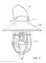
FIG. 1 depicts a preferred embodiment of the invention;
FIG. 2 shows the article with the LEDs activated;
FIG. 3 is a top view of the lantern, showing the solar cell and ON/OFF switch;
FIG. 4 is a detail view of the simulated Edison bulb; and
FIG. 5 is a block diagram of the electronics contained in the housing.
DETAILED DESCRIPTION OF THE INVENTION
FIG. 1 depicts a preferred embodiment of the invention. The invention includes a housing 102 coupled to a shade portion 106. These aspects are preferably stamped metal. For suspending the article, a hanger 104 attaches to both sides of the housing at 105. Under shade 106 a bulb 112 is coupled to the bottom of the housing. An optional decorative cage 108 surrounds the bulb 112. The bottom of the cage terminates in a fitting 110 adapted to receive a vertical rod (not shown) for upright ground support.
The simulated bulb uses light-emitting diodes as described in further detail below. FIG. 2 shows the article with the LEDs activated. FIG. 3 is a top view of the lantern, showing the solar cell 200 and ON/OFF switch 202.
FIG. 4 is a detail view of the simulated Edison bulb 402. The bulb includes an outer transparent shell 406 made of glass or plastic attached to a base 404. A stem assembly 408 within the shell 406 includes a distal disc 410 separated from a proximal disk 412 separated by a tube 414. The proximal disc is mounted to the base 404 via a hollow tube 416. The discs and tubes are preferably also made of a clear glass or plastic to simulate the inner portions of a vintage Edison bulb.
A plurality of LEDs 420 are supported between the spaced-apart discs, with one lead of each being connected at point 422, and the other ends of the LEDs being connected to lead 426. Thus, the LEDs are preferably connected in parallel, with the leads 422, 426 being routed out and through the base 404 for interconnection to the circuit shown in FIG. 5. To enhance the simulation, each LED is potted with a glob of translucent material such as silicone or the like to appear as a “filament.” Further, yellowish LEDs are preferably used as opposed to high-brightness or white LEDs to simulate incandescence.
FIG. 5 is a block diagram of the electronics contained in the housing. Solar panel 200 charges a rechargeable battery 502 that provides power to microcontroller 500. Microcontroller 500 provides power to LEDs 420. An optional ON/OFF switch 202 may be provided. In the preferred embodiment, a light sensor is included such that the battery charges during the day and the LEDs do not light up until a predetermined level of dusk or darkness is achieved. Either an optional photocell may be used as a light sensor or, more preferably, solar cell 200 may be used.
Claims
1. A solar-powered lantern, comprising:
a housing having an upper edge defining an upper surface, a lower edge defining a lower surface, and a sidewall between the upper and lower edges;
wherein the lower edge of the housing transitions into a shade portion extending downwardly from the housing;
a light bulb extending downwardly from the lower surface of the housing;
a cage extending downwardly from the housing and surrounding the light bulb;
a hanger having two ends coupled to opposing sidewalls of the housing;
a solar panel disposed on the upper surface of the housing;
a rechargeable battery disposed in the housing, and wherein the rechargeable battery is recharged with electrical energy generated by the solar panel; and
wherein the light bulb is a simulated Edison bulb including an outer transparent or translucent shell encapsulating and elongated simulated filament defined by a plurality of LEDs powered by the rechargeable battery.
2. The solar-powered lantern of claim 1, wherein:
the housing is cylindrical; and
the shade is a conical shade having an upper edge coinciding with the lower edge of the housing.
3. The solar-powered lantern of claim 1, wherein the ends of the hanger a pivotally coupled to the sidewalls of the housing.
4. The solar-powered lantern of claim 1, wherein the cage is comprised of intersecting horizontal and vertical elements with gaps therebetween.
5. The solar-powered lantern of claim 1, wherein the cage includes a lower portion with a connector adapted for coupling to a vertical support.
6. The lantern if claim 1, wherein the LEDs are yellowish in color.
7. The lantern if claim 1, wherein the housing and shade are metallic.
8. The lantern if claim 1, wherein the cage is metallic.
9. The lantern if claim 1, further including a light sensor such that the battery charges during the day and the LEDs do not light up until a predetermined level of dusk or darkness is achieved.
10. The lantern if claim 9, wherein the light sensor is a separate device or the solar panel is used as a light sensor.
Images & Drawings included:


Sources:
- United States Patent and Trademark Office - verify current appl. status at the USPTO↗
Recent applications in this class:
- » 20250290610 2025-09-18
Solar Powered Light - » 20250251100 2025-08-07
FOUNTAIN LAMP WITH WATER ENTRY SENSING AND DISINFECTION DEVICE - » 20250060080 2025-02-20
SAFETY LIGHT DEVICE - » 20250012416 2025-01-09
OUTDOOR LIGHTING SYSTEM - » 20240410541 2024-12-12
System and method of recycling light in home/store/commercial and street light fixtures - » 20240302010 2024-09-12
Solar magnetic suction linear lamp - » 20240084986 2024-03-14
MULTI-OPERATIONAL LANDSCAPE LIGHTING DEVICE - » 20240084985 2024-03-14
Intelligent solar powered lamps and methods of controlling operation of the same - » 20240044465 2024-02-08
PHOTOVOLTAIC SUNSHADE AND DISPLAY SYSTEM - » 20230408052 2023-12-21
Solar powered lamp attachment assembly