Pathlight
US20180216812A1
2018-08-02
15/886,682
2018-02-01
✅ Patent granted
US 10,598,368 B2
2020-03-24
-
-
Ali Alavi
Cermak Nakajima & McGowan LLP | Malcolm K. McGowan
2038-06-01
Abstract:
Pathlights for illuminating paths, walkways, and other landscape and architectural features advantageously incorporate light emitting diodes (“LEDs”) as an illumination source, and a visor which both directs the light and dissipates heat generated by the LEDs.
Assignee:
- AURORALIGHT, INC. 3 🇺🇸 Carlsbad, CA, United States
Applicant:
Interested in similar patents?
Get notified when new applications in this technology area are published.
Classification:
F21V11/00 » CPC further
Screens not covered by groups , , or
F21S8/086 » CPC further
Lighting devices intended for fixed installation with a standard of high-built type, e.g. street light with lighting device attached sideways of the standard, e.g. for roads and highways
F21S8/08 IPC
Lighting devices intended for fixed installation with a standard
F21V7/24 » CPC further
Reflectors for light sources characterised by materials, surface treatments or coatings, e.g. dichroic reflectors characterised by the material
F21V14/02 » CPC further
Controlling the distribution of the light emitted by adjustment of elements by movement of light sources
F21V23/06 » CPC further
Arrangement of electric circuit elements in or on lighting devices the elements being coupling devices, e.g. connectors
F21Y2115/10 » CPC further
Light-generating elements of semiconductor light sources Light-emitting diodes [LED]
F21V29/89 » CPC further
Protecting lighting devices from thermal damage; Cooling or heating arrangements specially adapted for lighting devices or systems characterised by the material Metals
F21V29/70 » CPC main
Protecting lighting devices from thermal damage; Cooling or heating arrangements specially adapted for lighting devices or systems; Cooling arrangements characterised by passive heat-dissipating elements, e.g. heat-sinks
F21W2131/10 » CPC further
Use or application of lighting devices or systems not provided for in codes - Outdoor lighting
F21V21/116 » CPC further
Supporting, suspending, or attaching arrangements for lighting devices ; Hand grips; Pendants, arms, or standards; Fixing lighting devices to pendants, arms, or standards Fixing lighting devices to arms or standards
F21W2131/109 » CPC further
Use or application of lighting devices or systems not provided for in codes -; Outdoor lighting of gardens
F21V21/00 IPC
Supporting, suspending, or attaching arrangements for lighting devices ; Hand grips
Description
FIELD OF ENDEAVOR
The present invention relates to devices, systems, and processes useful in the construction of optical lighting devices.
BRIEF DESCRIPTION OF THE RELATED ART
Prior pathlights have been available in many different configurations. Heat from the light sources, e.g., bulbs, often is difficult to dissipate while still providing a pathlight that can be oriented in different directions.
SUMMARY
Described herein are pathlights for illuminating paths, walkways, and other landscape and architectural features. The pathlight described advantageously incorporates light emitting diodes (“LEDs”) as an illumination source, and a visor which both directs the light and dissipates heat generated by the LEDs.
BRIEF DESCRIPTION OF THE DRAWINGS
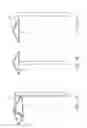
FIG. 1A shows one example of a pathlight as described herein, in isometric view, and FIGS. 1B and 1C show examples of a pathlight as described herein in elevational views.
FIG. 2A shows an exploded view of a pathlight as described herein, in isometric view, and FIG. 2B shows an exploded, perspective view of a pathlight as described herein.
FIG. 3 shows an expanded view of a pathlight as described herein, with the visor removed to show the attachment of the LED module to the horizontal member.
FIG. 4A shows an isometric view and FIG. 4B shows an exploded view of an LED module as described herein.
DETAILED DESCRIPTION
Provided herein is a pathlight having a vertical support member 1; a horizontal support member 2 attached to the vertical support member 1; an LED module 4 having at least one light emitting diode; means 5 for rotatably attaching the LED module 4 to the horizontal support member 2; and a top or visor 3 removably attached to the means 5 for rotatably attaching, wherein the visor 3 is configured to dissipate heat generated by the LED module.
The support members may be solid, or hollow. As shown in FIGS. 2A and 2B, when the support members 1, 2 are hollow, a connector 10 electrically connects the LED module 4 to a power source may be disposed within the lumen of the hollow support members 1, 2. The support members 1, 2 may be of any suitable shape in cross-section. In the embodiment shown in FIGS. 2A and 2B, the support members 1, 2, are square in cross-section.
The visor 3 may be of any desired shape, provided that the shape does not interfere with the ability of the visor to dissipate heat generated by the LED module. In the embodiment shown in FIGS. 1A-1C, the visor 3 is pyramidal in shape. The visor 3 may be transparent, translucent, or opaque. The side of the visor 3 adjacent to the LED module 4 may be covered with a reflective material. The visor 3 may be advantageously constructed of a metal which combines heat dissipation properties and corrosion resistance, such as copper or brass.
The LED module is mounted to the horizontal member by a bracket 7, as shown in FIG. 3, or other means that permit it to rotate in the plane formed by the vertical and horizontal support members. In the embodiment shown in FIG. 3, the LED module 4 can rotate through 60° in the plane formed by the vertical 1 and horizontal 2 support members.
The LED module 4 will contain one or more light emitting diodes; in the embodiment shown in FIG. 3, the LED module 4 includes three light emitting diodes 6.
The LED module 4 may be of any suitable shape that permits rotation. For example, the LED module may be substantially cylindrical. In the embodiment shown in FIGS. 4A and 4B, the LED module 4 has a central cylindrical section 7, and first 8 and second 9 frustoconical sections disposed at opposite ends of the cylindrical section 7. In the embodiment shown in FIGS. 4A and 4B, one light emitting diode is mounted in each of the cylindrical section 7 and the first 8 and second 9 frustoconical sections. Optionally, the frustoconical sections are rotatably attached to the cylindrical section.
The preceding is merely a detailed description of various embodiments of this invention and that numerous changes to the disclosed embodiments can be made in accordance with the disclosure herein without departing from the spirit or scope of the invention. Rather, the scope of the invention is to be determined only by the appended claims and their equivalents.
Claims
What is claimed is:1. A pathlight comprising
a vertical support member;
a horizontal support member attached to the vertical support member;
an LED module comprising a plurality of light emitting diodes;
a visor;
means for rotatably attaching the LED module to the horizontal support member or visor;
wherein the visor is removably attached to the means for rotatably attaching; and
wherein heat from the rotatable LED module can be dissipated through the visor and/or the horizontal support member.
2. The pathlight of claim 1, wherein the vertical and horizontal support members are hollow.
3. The pathlight of claim 2, further comprising means for electrically connecting the LED module to a power source, wherein the means for connecting is disposed within the lumen of the hollow support members.
4. The pathlight of claim 1, wherein the visor is pyramidal in shape.
5. The pathlight of claim 1, wherein the visor is opaque.
6. The pathlight of claim 5, wherein at least one surface of the visor is covered with a reflective material.
7. The pathlight of claim 5, wherein the visor comprises copper or brass.
8. The pathlight of claim 1, wherein the vertical support member is square in cross-section.
9. The pathlight of claim 1, wherein the horizontal support member is square in cross-section.
10. The pathlight of claim 1, wherein the LED module is configured to rotate through 60° in a plane formed by the vertical and horizontal support members.
11. The pathlight of claim 1, wherein the LED module comprises three light emitting diodes.
12. The pathlight of claim 1, wherein the LED module comprises a central cylindrical section, and first and second frustoconical sections disposed at opposite ends of the cylindrical section.
13. The pathlight of claim 12, wherein at least one light emitting diode is mounted in each of the cylindrical section and the first and second frustoconical sections.
14. The pathlight of claim 12, wherein the frustoconical sections are rotatably attached to the cylindrical section.
Images & Drawings included:


Sources:
- United States Patent and Trademark Office - verify current appl. status at the USPTO↗
Similar patent applications:
Recent applications in this class:
- » 20250237374 2025-07-24
Stage Light With Heat Dissipation - » 20240337374 2024-10-10
Lamp - » 20240310030 2024-09-19
Modular Floodlight System with Supplemental Motion Detection - » 20240210024 2024-06-27
Deterrent Device Attachment Having Light Source With Thermal Management - » 20240200767 2024-06-20
CURING LIGHT WITH HEAT DISSIPATION STRUCTURE - » 20240151388 2024-05-09
LED lamp - » 20240085011 2024-03-14
Active thermal-control of a floodlight and associated floodlights - » 20240085010 2024-03-14
LIGHT-EMITTING DEVICE - » 20230358393 2023-11-09
Luminaire with LED lights provided with heat sink - » 20230304655 2023-09-28
Electronic device, light emitting device and method for manufacturing an electronic device
Recent applications for this Assignee:
- » 20190041010 2019-02-07
Optical device alignment and identification - » 20170051880 2017-02-23
Light module with self-aligning electrical and mechanical connection