Display assembly
US20180246541A1
2018-08-30
15/905,260
2018-02-26
✅ Patent granted
US 10,296,042 B2
2019-05-21
-
-
Nidhi Thaker
Zarley Law Firm, P.L.C.
2038-02-26
Abstract:
A display assembly having a top member connected to a bottom member. The top member has a top wall, sidewalls, and a flange having an outer edge that extends outwardly from the sidewalls. The bottom member has a bottom wall, sidewalls, a flange that extends outwardly from the sidewall, and an outer ridge on the flange that extends toward the top member.
Assignee:
- Christal Clear Showcases, LLC 1 🇺🇸 Ankeny, IA, United States
Applicant:
Interested in similar patents?
Get notified when new applications in this technology area are published.
Classification:
G06F1/1601 » CPC main
Details not covered by groups - and; Constructional details or arrangements Constructional details related to the housing of computer displays, e.g. of CRT monitors, of flat displays
A47F3/145 » CPC further
Show cases or show cabinets; Display trays or containers Closable display containers
A47F3/004 » CPC further
Show cases or show cabinets adjustable, foldable or easily dismountable
G02F1/133308 » CPC further
Devices or arrangements for the control of the intensity, colour, phase, polarisation or direction of light arriving from an independent light source, e.g. switching, gating or modulating; Non-linear optics for the control of the intensity, phase, polarisation or colour based on liquid crystals, e.g. single liquid crystal display cells; Constructional arrangements; Operation of liquid crystal cells; Circuit arrangements; Constructional arrangements; Manufacturing methods Support structures for LCD panels, e.g. frames or bezels
A47F3/00 IPC
Show cases or show cabinets
A47F3/14 IPC
Show cases or show cabinets Display trays or containers
G06F1/16 IPC
Details not covered by groups - and Constructional details or arrangements
G09G3/20 » CPC further
Control arrangements or circuits, of interest only in connection with visual indicators other than cathode-ray tubes for presentation of an assembly of a number of characters, e.g. a page, by composing the assembly by combination of individual elements arranged in a matrix no fixed position being assigned to or needed to be assigned to the individual characters or partial characters
G02F1/1333 IPC
Devices or arrangements for the control of the intensity, colour, phase, polarisation or direction of light arriving from an independent light source, e.g. switching, gating or modulating; Non-linear optics for the control of the intensity, phase, polarisation or colour based on liquid crystals, e.g. single liquid crystal display cells; Constructional arrangements; Operation of liquid crystal cells; Circuit arrangements Constructional arrangements; Manufacturing methods
G06F1/1637 » CPC further
Details not covered by groups - and; Constructional details or arrangements for portable computers; Constructional details or arrangements of portable computers not specific to the type of enclosures covered by groups - Details related to the display arrangement, including those related to the mounting of the display in the housing
Description
CROSS REFERENCE TO RELATED APPLICATION
This application claims the benefit of U.S. Provisional Application No. 62/463,123 filed Feb. 24, 2017.
BACKGROUND OF THE INVENTION
This invention is directed to a display assembly and more particularly a display assembly that improves upon conventional display assemblies.
Display assemblies are well known in the art for use in displaying merchandise such as coins, stamps, jewelry, and the like. Existing display assemblies are heavy, take up a lot of space, take time to assemble and breakdown, and are difficult to handle. Therefore, a need exists in the art for a display assembly that addresses these needs.
An objective of the present invention is to provide a display assembly that is lightweight and takes up a minimum amount of space.
Another objective of the present invention is to provide a display assembly that is easy to assemble, break down, and handle.
These and other objectives will be apparent to those skilled in the art based upon the following written description, drawings and claims.
SUMMARY OF THE INVENTION
A display member has a top member connected to a bottom member. The top member has a top wall, sidewalls, and a flange that extends outwardly from the sidewalls to an outer edge. Extending outwardly from the outer edge on opposite sides is at least one connecting tab and at least one locking tab.
The bottom member has a bottom wall, sidewalls, and a flange that extends outwardly from the sidewalls to an upwardly extending outer ridge. The flange of the top member nests within the outer ridge of the bottom member and is supported by the flange on the bottom member.
On one side of the bottom member the outer ridge is interrupted to form at least one opening that aligns with and receives the at least one locking tab. On an opposite side the outer ridge has at least one slot that aligns with and receives the at least one connecting tab. The at least one locking tab has an aperature that receives a locking mechanism.
BRIEF DESCRIPTION OF THE DRAWINGS
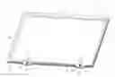
FIG. 1 is a top perspective view of a display assembly;
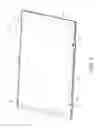
FIG. 2 is a bottom perspective view of a display assembly;
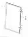
FIG. 3 is a top perspective view of a locking tab and locking mechanism; and
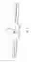
FIG. 4 is a bottom perspective view of a locking tab and locking mechanism.
DETAILED DESCRIPTION
Referring to the Figures, a display assembly 10 has a top member 12 and a bottom member 14 that are hingedly connected. The top member 12 has a top wall 16 and sidewalls 18 that form a compartment 20. In one embodiment, the sidewalls 18 angle outwardly from the top wall 16. The sidewalls 18 terminate in an outwardly extending flange 22 having an outer edge 24. Extending outwardly from the outer edge 24 on one side of the top member 12 is at least one, and preferably three connecting tabs 26. On the opposite side of the top member 12 and extending outwardly from the outer edge is a locking tab 28. The locking tab 28 has an opening or aperture 30.
The bottom member 14 has a bottom wall 32 and sidewalls 34 that form a compartment 36 that is generally aligned with compartment 20 of the top member 12. The sidewalls 34 terminate in outwardly extending flanges 38 that are positioned to align, engage and support flange 22 of the top member 12. Flange 38 terminates in an outer ridge 40 that extends toward the top member 12 such that flange 22 of the top member nests within the outer ridge 40.
On one side of the bottom member 14, the outer ridge 40 is interrupted to form an opening 42. The opening is positioned adjacent to locking tab 28 of the top member 12. Alternatively, there are two openings 42 that each align with a locking tab 28. On a side opposite opening 42, the outer ridge 40 has at least one and preferably three slots 44. The slots 44 are positioned to align with connecting tabs 26 and are formed to receive the connecting tabs 26 of the top member 12.
Extending through aperture 30 is a locking mechanism 46. The locking mechanism is of any size, shape, and structure. In a preferred embodiment the locking mechanism 46 has a head 48 having a diameter greater than the diameter of aperture 30. A locking shaft 50 is rotatably connected to and extends through the head 48 as well as aperture 30. The shaft 50 has a slot 52 at one end formed to receive a key. Attached to the opposite end of the locking shaft 50 is a locking arm 54.
In operation, to assemble, connecting tabs 26 of the top member 12 are aligned with slots 44 of the bottom member 14 and tabs 26 are slid into slots 44. Tabs 26 are of a pliable material or have a fold line that permit the top member 12 to be raised while still connected to the bottom member 14 in a hinged manner.
Next, the top member 12 is lowered so that flange 22 rests upon flange 38 and nests within outer ridge 40. To lock the assembly, a key is inserted into slot 52 and shaft 50 is rotated. The rotation of shaft 50 also rotates locking arm 50 so that it engages a bottom surface of flange 38 at opening 42 of outer ridge 40. In this position, the top member 12 is locked to the bottom member. To unlock, using the key, the shaft 50 is rotated in the opposite direction causing locking arm 54 to rotate out of engagement with flange 38.
In addition, the top member 12 and bottom member 14 easily detach from one another. Once detached top member 12 can be stacked or nested within one another and bottom members 14 can be stacked or nested within one another to ease transport and save storage space when multiple cases are in use.
Claims
What is claimed is:1. A display assembly, comprising:
a top member having a top wall, a sidewall, and a flange that extends outwardly from the sidewall;
a bottom member having a bottom wall and sidewalls connected to the top member;
a flange that extends outwardly from the sidewalls of the bottom member that are positioned to align, engage, and support the flange of the top member; and
an outer ridge on the flange of the bottom member that extends toward the top member and permits the flange of the top member to nest within the outer ridge.
2. The display assembly of claim 1 wherein the outer ridge on one side of the bottom member is interrupted to form at least one opening.
3. The display assembly of claim 2 wherein the top member has at least one locking tab that extends outwardly from the flange of the top member and aligns with the at least one opening in the outer ridge of the bottom member.
4. The display assembly of claim 2 wherein opposite the one side of the bottom member has at least one slot.
5. The display assembly of claim 4 wherein the top member has at least one connecting tab that extends outwardly from the outer edge of the flange and is positioned to align with and be received within the slots of the bottom member.
6. The display assembly of claim 3 wherein the at least one locking tab of the top member has an aperature that receives a locking mechanism.
Images & Drawings included:

Sources:
- United States Patent and Trademark Office - verify current appl. status at the USPTO↗
Similar patent applications:
- » 20170106996
Display assembly, use of a display assembly, and aircraft assembly having such a display assembly - » 20230420828
DISPLAY ASSEMBLY, CLIENT DEVICE COMPRISING THE DISPLAY ASSEMBLY, AND METHOD OF MANUFACTURING THE DISPLAY ASSEMBLY - » 20190189644
Array substrate for display assembly, display assembly and electronic equipment - » 20200411599
Display assembly, electronic device, and method for assembling display assembly - » 20220383832
Display assembly, display device and driving method for display assembly each combining data signals as dimming signal - » 20190286192
Glass cover plate for a display assembly, display assembly, and terminal - » 18504065
Display assembly, method for operating display assembly, and display - » 20210408411
Protective film, display module, display assembly, method for preparing display assembly and display device - » 20080131184
Display key, display keyswitch assembly, key display assembly, key display, display data entry device, display PC keyboard, and related methods - » 20220287183
Flexible circuit board assembly, display assembly and display device
Recent applications in this class:
- » 20250278114 2025-09-04
CONFIGURABLE DISPLAY HOLDING APPARATUS AND SYSTEM - » 20250278113 2025-09-04
ELECTRONIC APPARATUS AND CHASSIS MEMBER - » 20250244788 2025-07-31
Cleaning a Touch Screen - » 20250181108 2025-06-05
ELECTRONIC APPARATUS - » 20250155920 2025-05-15
DEVICE WITH A TOUCHSCREEN WHICH COMPRISES A SELF-SUPPORTING PLATE - » 20250103093 2025-03-27
DISPLAY DEVICE AND ELECTRONIC DEVICE - » 20250076919 2025-03-06
ELECTRONIC DEVICE - » 20250060778 2025-02-20
Portable, Protective Gaming Case with Built-In Monitor - » 20250004498 2025-01-02
DISPLAY DEVICE AND CONTROL METHOD THEREOF - » 20240385646 2024-11-21
DISPLAY APPARATUS