Field device with a component for filling potting compound
US20180249587A1
2018-08-30
15/753,413
2016-07-26
✅ Patent granted
US 10,631,421 B2
2020-04-21
WO; PCT/EP2016/067748; 20160726
WO; WO2017/032529; 20170302
Stanley Tso
Christopher R. Powers | PatServe
2036-09-20
Abstract:
The invention relates to a field device of automation technology with an opened housing and an electronics part in the housing, comprising at least one component for filling potting compound into the housing, wherein the component has a trough, in order to conduct the potting compound, with targeting, to a location of the housing to be potted.
Inventors:
- Willy Huwyler 5 🇨🇭 Cham, Switzerland
- Christian SEILER 1 🇩🇪 Neuenburg am Rhein, Germany
- Silvio MOSER 1 🇨🇭 Hausen, Switzerland
Assignee:
- Endress+Hauser SE+Co. KG 192 🇩🇪 Maulburg, Germany
Applicant:
Interested in similar patents?
Get notified when new applications in this technology area are published.
Classification:
H05K5/064 » CPC main
Casings, cabinets or drawers for electric apparatus; Hermetically-sealed casings sealed by potting, e.g. waterproof resin poured in a rigid casing
H05K5/064 » CPC main
Casings, cabinets or drawers for electric apparatus; Hermetically-sealed casings sealed by potting, e.g. waterproof resin poured in a rigid casing
H05K5/00 IPC
Casings, cabinets or drawers for electric apparatus
H05K5/00 IPC
Casings, cabinets or drawers for electric apparatus
B29C39/10 » CPC further
Shaping by casting, i.e. introducing the moulding material into a mould or between confining surfaces without significant moulding pressure; Apparatus therefor for making articles of definite length, i.e. discrete articles incorporating preformed parts or layers, e.g. casting around inserts or for coating articles
B29C39/26 » CPC further
Shaping by casting, i.e. introducing the moulding material into a mould or between confining surfaces without significant moulding pressure; Apparatus therefor; Component parts, details or accessories; Auxiliary operations Moulds or cores
G01D11/245 » CPC further
Component parts of measuring arrangements not specially adapted for a specific variable; Housings ; Casings for instruments Housings for sensors
H05K7/1462 » CPC further
Constructional details common to different types of electric apparatus; Mounting supporting structure in casing or on frame or rack for programmable logic controllers [PLC] for automation or industrial process control
H05K7/1462 » CPC further
Constructional details common to different types of electric apparatus; Mounting supporting structure in casing or on frame or rack for programmable logic controllers [PLC] for automation or industrial process control
B29L2031/34 » CPC further
Other particular articles Electrical apparatus, e.g. sparking plugs or parts thereof
H05K5/06 IPC
Casings, cabinets or drawers for electric apparatus Hermetically-sealed casings
H05K5/06 IPC
Casings, cabinets or drawers for electric apparatus Hermetically-sealed casings
G01D11/24 IPC
Component parts of measuring arrangements not specially adapted for a specific variable Housings ; Casings for instruments
H05K7/14 IPC
Constructional details common to different types of electric apparatus Mounting supporting structure in casing or on frame or rack
H05K7/14 IPC
Constructional details common to different types of electric apparatus Mounting supporting structure in casing or on frame or rack
Description
The invention relates to a field device of automation technology with an opened housing and an electronics part in the housing, comprising at least one component for filling a potting compound into the housing.
Sensors or electronic inserts are filled with the most varied of potting compounds in the electronics- or final manufacture for different reasons, such as e.g. protection against moisture or explosion protection. In such case, the potting compound is, in most cases, cast with the assistance of the force of gravity under usual atmospheric conditions from above into housing openings. In such case, the material flows relatively without control around the electronic parts present in the housing and finds its paths for itself. Air inclusions and bubble formation cannot always be excluded using this method, so that different approaches are used for preventing the bubbles and air inclusions. Examples include filling under vacuum, long cure times after potting (bubbles should rise), stepwise casting (with interspersed quiet times), vibrating the potting compound, and filling under pressure.
The described methods often deliver non-reproducible results or do not permit high working speeds, since back pressure can occur from bottlenecks in the housing or air cannot sufficiently escape in the case of narrow filling locations. If additional measures are applied, higher costs of the product result.
DE 102008043169 A1 describes an apparatus with a housing, which has an opening. The housing includes a first housing section, in which a sensor electronics is arranged. An insert is inserted into the first housing section, wherein the insert comprises a tubular, basic body. A filling tube is introduced into the insert and serves to fill the insert with a first potting compound. The filling tube introduced into the insert enables a filling of the potting compound into the insert, without giving rise to air inclusions.
Disadvantageous in the case of the application of a filling tube is that, for space reasons a, most often, very small diameter of the filling tube must be used. The small opening requires performing the filling under pressure, in order to be able to assure a sufficient filling speed. The junction between filling tube and potting machine must be appropriately shape-interlocked, which requires a very precise orientation of a fill needle. Further disadvantageous in the case of such a filling tube is that, after the filling of the housing with potting compound, it remains in the housing, since a withdrawal of the filling tube from the potting compound would introduce more air into the potting compound.
An object of the invention is to provide a field device of automation technology, which enabled a rapid filling of potting compound into the housing of the field device even through narrow openings, without giving rise to air inclusions in the potting compound.
The object of the invention is achieved by the subject matter of the invention. Subject matter of the invention is a field device of automation technology with an opened housing and an electronics part in the housing, comprising at least one component for filling potting compound into the housing, wherein the component has a trough, in order to conduct the potting compound, with targeting, to a location of the housing to be potted.
The field device of the invention enables a targeted filling and de-airing of the housing, without turbulence occurring in the potting compound. Furthermore, bubble formation is suppressed, whereby air inclusions are avoided.
In an advantageous embodiment, the component is embodied as a cable holder for at least one cable led into the housing.
In an advantageous form of embodiment, the trough includes a collecting pan, which faces a housing opening, and a channel, which points in the direction of a housing interior.
In an advantageous variant, the channel is dimensioned in such a way that the potting compound is conveyed to a gap to be potted, for example, a gap between the electronics part and an inner surface of the housing, in order that the potting compound can run down orderly.
In an advantageous further development, the component includes at least one opening for de-airing the housing.
In an advantageous embodiment, the collecting pan is arranged beside the at least one opening.
In an advantageous form of embodiment, the collecting pan extends around the at least one opening.
The invention will now be explained in greater detail based on the appended drawing, the figures of which show as follows:
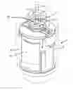
FIG. 1 a perspective view of the component of a field device of automation technology, and
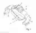
FIG. 2 a perspective view of a transparent housing of a field device of automation technology.
FIG. 1 shows a component 1 for a housing (not shown) of a field device of automation technology (not shown). Component 1 serves, on the one hand, for filling potting compound into the housing and, on the other hand, as a cable holder. For holding a cable (not shown), the component 1 includes an opening 11.
Component 1 includes a trough 4, which includes a collecting pan 6 and a channel 8. The collecting pan 6 is arranged in an upper region of the component 1 and extends around the opening 11 and opens into the channel 8, which is arranged in a lower region of the component 1. Furthermore, the component 1 includes holders 12 for securing to a housing (not shown).
FIG. 2 shows a perspective view of a transparent housing of a field device of automation technology. Installed in the housing 3 is a component 1 of FIG. 1. Component 1 is embodied as a cable holder for a cable 5. Housing 3 includes a housing opening 7 and the collecting pan 6 of the component 1 faces in the direction of the opening 7. As a result, the channel (not shown) of the component 1 is directed toward the housing interior. Of course, the housing can have besides a number of components also a component with a number of collecting pans or a number of channels.
Arranged in the housing interior of the housing 3 is an electronics part 10. In this way, there arises a gap 9 between the inner surface of the housing 3 and the electronics part 10. The casting of the potting compound into the housing 3 of the field device occurs in the following way: The liquid potting compound is cast through the housing opening 7 into the collecting pan 6 of the component 1. The liquid potting compound flows from the collecting pan 6 into the channel (not visible) of the component 1. The flow direction of the potting compound is shown by arrows. The channel conducts the potting compound to the gap between the electronics part 10 and the inner surface of the housing 3. The potting compound flows into the gap 9, wherein the pushed air can escape through the opening 11 of the component 1 and the housing opening 7.
LIST OF REFERENCE CHARACTERS
1 component
2 potting compound
3 housing
4 trough
5 cable
6 collecting pan
7 housing opening
8 channel
9 gap
10 electronics part
11 opening
12 holder
Claims
1-7. (canceled)
8. A field device of automation technology, comprising:
a housing including a housing opening;
an electronics part disposed within the housing; and
a fill component for dispensing potting compound into the housing, wherein the fill component includes a trough structured to conduct the potting compound, with targeting, to a location within the housing to be potted.
9. The field device of claim 8, wherein the fill component is embodied as a cable holder for at least one cable passing into the housing.
10. The field device of claim 8, wherein the trough includes a collecting pan, which faces in the direction of the at least one opening, and a channel, which leads in the direction of a housing interior.
11. The field device of claim 10, wherein the channel is shaped such that the potting compound is conveyed into a gap such that the potting compound flows into the gap without entrapping air in the housing or potting compound, the gap being between the electronics part and an inner surface of the housing.
12. The field device of claim 8, wherein the fill component includes at least one component opening for de-airing the housing.
13. The field device of claim 10, wherein the collecting pan is arranged beside the at least one component opening.
14. The field device of claim 10, wherein the collecting pan extends around the at least one component opening.
Images & Drawings included:
Sources:
- United States Patent and Trademark Office - verify current appl. status at the USPTO↗
Recent applications in this class:
- » 20250169014 2025-05-22
ELECTRICAL DEVICE WITH POTTING MATERIAL - » 20250048578 2025-02-06
PRINTED CIRCUIT BOARD FOR AN AUTOMATION FIELD DEVICE - » 20240196556 2024-06-13
Electronics unit - » 20220330447 2022-10-13
ELECTRIC CIRCUIT BOARD AND POWER MODULE - » 20220061179 2022-02-24
Display panel bend reinforcement - » 20210352816 2021-11-11
Explosion proof feed-through - » 20210084785 2021-03-18
Electronic device - » 20200288594 2020-09-10
FLUID METER, ENERGY STORAGE DEVICE FOR A FLUID METER, AND METHOD - » 20200060035 2020-02-20
Heat dissipation in an electronic circuit and method - » 20190373749 2019-12-05
Power supply device with PCB positioning function and method for manufacturing the same
Recent applications for this Assignee:
- » 20240137021 2024-04-25
Level converter - » 20240125639 2024-04-18
Level fork protection sleeve - » 20240068895 2024-02-29
DIFFERENTIAL PRESSURE SENSOR FOR DETERMINING THE DIFFERENTIAL PRESSURE BETWEEN TWO PRESSURES - » 20240060841 2024-02-22
Pressure gauge for measuring a pressure - » 20240022250 2024-01-18
Method for operating an optoelectronic touch and/or operating element - » 20240003732 2024-01-04
FILL-LEVEL MEASURING DEVICE - » 20230417591 2023-12-28
METHOD FOR OPERATING A VIBRONIC SENSOR - » 20230400342 2023-12-14
FILL-LEVEL MEASUREMENT DEVICE - » 20230314253 2023-10-05
Pressure measuring unit for measuring a pressure - » 20230314252 2023-10-05
HYDRAULIC PRESSURE TRANSMISSION DEVICE, AND PRESSURE SENSOR HAVING A HYDRAULIC PRESSURE TRANSMISSION DEVICE