Rotational valve for two stroke engine
US20180266336A1
2018-09-20
15/530,869
2017-03-14
✅ Patent granted
US 10,914,205 B2
2021-02-09
-
-
Mahmoud Gimie
Ingenium Patents LLC | Peter R. Kramer
2037-03-14
Abstract:
A two stroke internal combustion engine having a piston reciprocating in a cylinder between TDC and BDC positions to influence a crank shaft with help of a connecting rod. A Rotational Valve (RV) associated with the cylinder body selectively altering the timing and duration of opening and closing of cylinder intake and exhaust ports. The said rotational Valve may be associated with the said crank shaft through a drive train assembly. Drive train assembly may control the Rotational Valve through electronic or mechanical means.
Applicant:
Interested in similar patents?
Get notified when new applications in this technology area are published.
Classification:
F02D13/0215 » CPC main
Controlling the engine output power by varying inlet or exhaust valve operating characteristics, e.g. timing during engine operation; Variable control of intake and exhaust valves changing the valve timing only
F02D41/26 » CPC further
Electrical control of supply of combustible mixture or its constituents characterised by the use of digital means using computer, e.g. microprocessor
F02D13/028 » CPC further
Controlling the engine output power by varying inlet or exhaust valve operating characteristics, e.g. timing during engine operation for two-stroke engines
F02D41/0002 » CPC further
Electrical control of supply of combustible mixture or its constituents Controlling intake air
F02B75/02 » CPC further
Other engines Engines characterised by their cycles, e.g. six-stroke
F01L5/06 » CPC further
Slide valve-gear or valve-arrangements with cylindrical, sleeve, or part-annularly shaped valves surrounding working cylinder or piston
F02D41/00 IPC
Electrical control of combustion engines
F02D41/00 IPC
Electrical control of supply of combustible mixture or its constituents
F01L5/20 » CPC further
Slide valve-gear or valve-arrangements specially for two-stroke engines
F02B2075/025 » CPC further
Other engines; Engines characterised by their cycles, e.g. six-stroke having less than six strokes per cycle two
F02D2400/04 » CPC further
Control systems adapted for specific engine types; Special features of engine control systems not otherwise provided for; Power supply, connectors or cabling for engine control systems Two-stroke combustion engines with electronic control
Y02T10/12 » CPC further
Road transport of goods or passengers; Internal combustion engine [ICE] based vehicles Improving ICE efficiencies
Y02T10/12 » CPC further
Road transport of goods or passengers; Internal combustion engine [ICE] based vehicles Improving ICE efficiencies
F01L7/12 » CPC main
Rotary or oscillatory slide valve-gear or valve arrangements specially for two-stroke engines
F02D13/02 IPC
Controlling the engine output power by varying inlet or exhaust valve operating characteristics, e.g. timing during engine operation
F02B25/18 » CPC further
Engines characterised by using fresh charge for scavenging cylinders using reverse-flow scavenging, e.g. with both outlet and inlet ports arranged near bottom of piston stroke the charge flowing upward essentially along cylinder wall adjacent the inlet ports, e.g. by means of deflection rib on piston
Description
BACKGROUND OF THE INVENTION
The present invention relates broadly to two-stroke internal combustion engines, and more particularly to an arrangement for controlling the intake and exhaust port opening durations with help of a Rotational Valve.
First two-stroke internal combustion engine was invented and patented in the 1881 by Scottish engineer Dugald Clerk and were first placed in practical use by Alfred Angas Scott. He started using two-stroke engines in twin cylinder water cooled motorcycles and the two-stroke engine industry was borne.
Two-stroke internal combustion engines complete a power cycle with two strokes, up and down movements of the piston during only one crankshaft revolution in comparison to four-stroke engines which complete a cycle in 4 piston strokes. In two-stroke engines, in between the end of the combustion stroke and the beginning of the compression stroke, exhaust and intake (or scavenging) functions occur at the same time.
A two-stroke engine performs intake, compression, combustion, and exhaust cycles in 2 strokes of the piston. The distance the piston travels between the Top Dead Center (TDC) and the Bottom Dead Center (BDC) positions is referred to as a stroke length.
During the combustion stroke of a two-stroke engine, the piston recedes from TDC to BDC, and at around 120 crank degree mark, the exhaust port is uncovered by the piston to let exhaust gases out of the cylinder. This is often referred as the exhaust cycle. As these gases are extremely hot and have high pressure, they rush out of the cylinder in a couple crank degrees. As the piston continues to .recede towards the BDC, the intake port is uncovered by the piston to permit air into the combustion chamber, which is mixed with an appropriate amount of gasoline through carburetor.
Two-stroke engine utilizes the bottom part of the piston to compress the attendant by utilizing the piston's natural reciprocating motion, and with help of the bottom part volume being built air tight. As the piston travels to TDC, it uncovers the intake port and connects the bottom part of the cylinder to the intake manifold, the carburetor and to the atmospheric pressure. Continued motion of the piston towards TDC creates a low pressure in the bottom part of the piston, relative to atmospheric pressure, and therefore induces the air-fuel mixture to flow into the bottom part of the piston. As the piston reaches the TDC a flip valve is closed, which renders the bottom part of the piston airtight. With help of the piston traveling towards BDC and decreasing this section's volume; the next combustion cycle's attendant naturally becomes compressed.
As the piston continues to recede towards BDC, it will uncover the intake port, which is connected to the bottom part of the cylinder; this will result in the compressed mixture of air & fuel to be rushed into the combustion chamber starting the intake-scavenging cycle. As the intake/scavenging cycle continues, continued flow of air & fuel mixture is sustained, which induces more air fuel mixture in the cylinder. The intake port is covered as the piston passes the BDC and starts traveling toward the TDC. Covering of the intake port stops the attendant from entering the combustion chamber, while some attendant is lost due to the exhaust port still being open at this point. As the piston travels closer to the TDC it covers the exhaust port and the piston compresses the mixture as it moves closer to TDC. This is referred as the compression cycle.
Combustion starts as the piston passes TDC in the third cycle in response to a spark produced by the spark plug. As the reaction starts, atom by atom the temperature and pressure of the mixture raises drastically. This is usually referred as the combustion cycle. Reaction takes place in a very fast manner, and it may be observed as an explosion. As the piston passes TDC a few drive shaft degrees, most of the fuel inside the chamber has been consumed and the highest temperature and pressure has been achieved. The attendant increase in volume as the piston moves toward BDC causes the gas to start losing its pressure while the crank shaft assembly keeps moving to a higher moment arm position. The pressure of the gas influences a moment to the drive shaft with the help of the piston and the connecting rod to produce power. As the piston again passes through 120 crank degree mark, the first cycle begins again.
There are some major differences between four-stroke and two-stroke engines. Four-stroke engines have poppet valves, which lets the air fuel mixture into the cylinder and exhaust gases out. It also has the valve train, springs, camshafts, and timing belts. In contrast two-stroke engines don't have any of these assemblies; in this engine type the number of moving parts are greatly reduced; hence two-stroke engines have high power to weight ratio, so can be compact and much lighter.
A four-stroke engine must be positioned in a certain way due to lubrication being collected in the bottom oil collection pan. This is not necessary for two-stroke engines, due to oil is mixed to the fuel and is used to lubricate moving parts. Burning the fuel along with the lubricating oil results in creating more exhaust emissions than four-stroke engines.
Advantages of two-stroke engines can be listed as light weight, simple operation, reduced number of moving parts, multiple ways of positioning the unit.
Disadvantages of two-stroke engines are listed as low efficiency due to less compression of the attendant, and high emissions in comparison to four-stroke engines. In addition, there is significant loss of fuel due to exhaust port being covered after the intake port is covered.
There are some prior arts to improve disadvantages of two-stroke engines, such as rotational exhaust valve closing the exhaust duct when the piston reaches the bottom dead center. This assembly ends scavenging cycle and stops loss of air-fuel mixture from the combustion chamber. This is a good way to improve efficiency in two-stroke engines, but this assembly required drive train and introduces more moving parts into a simple engine. Also, there is always room for improvement.
To manufacture an efficient two-stroke engine, one endeavors to use less fuel for a given power output. In comparison to prior art design and specifications, it would be advantageous to devise an engine keeping more attendant in the combustion chamber, having lower emissions, and thus having an increased torque while at the same time consuming less fuel.
BRIEF SUMMARY OF THE INVENTION
The present invention achieves this result and overcomes the shortcomings of the prior art by controlling the intake and exhaust port opening timing and durations with help of a rotational valve and its drive train. The rotational valve has an opening or openings which are timed to align with intake and exhaust ports thereby form ducts to conduct air-fuel mixture and exhaust gases in and out of the cylinder and therefore controlling the intake and exhaust port opening timing and durations.
BRIEF DESCRIPTION OF THE DRAWINGS
The subject matter regarded as the invention is particularly pointed out and distinctly claimed in the concluding portion of the specification. The invention, however, both as to organization and method of operation, together with the features, objects, and advantages thereof, may best be understood by reference to the following detailed description when read with the accompanying drawings in which:
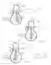
FIG. 1 is a is a partial cross-sectional view of certain internal components of a conventional two-stroke engine at the exhaust port is uncovered;
FIG. 2 is a partial cross-sectional view of certain internal components of a conventional two-stroke engine in the BDC position;
FIG. 3 is a is a partial cross-sectional view of certain internal components of a conventional two-stroke engine in the intake port is covered position;
FIG. 4 is a is a developed view of the rotational valve and associated components in accordance with one embodiment of the present invention,
FIG. 5 is a is a partial schematic cross-sectional view of an exemplary two-stroke engine in the intake port is covered position;
FIG. 6 is a schematic cross-sectional view of an exemplary two-stroke engine from the top down.
DETAILED DESCRIPTION
In the following are described the preferred embodiments of the rotational valve for two stroke engine in accordance with the present invention. In describing the embodiments illustrated in the drawings, specific terminology will be used for the sake of clarity. However, the invention is not intended to be limited to the specific terms so selected, and it is to be understood that each specific term includes all technical equivalents that operate in a similar manner to accomplish a similar purpose. Where like elements have been depicted in multiple embodiments, identical reference numerals have been used in the multiple embodiments for ease of understanding.
Referring to the drawings, and prior to addressing the preferred embodiments of the invention, reference is drawn to FIG. 1 which depicts a partial cross-sectional view of certain components of a conventional engine, such as a two stroke gasoline engine. As shown, the engine comprises an engine block 100 within which a cylinder 102 is cast or otherwise provided. The cylinder 102 houses a piston 104 which travels in a reciprocating manner along a centerline 106 of the cylinder 102. Of course, although shown in a generally vertical orientation in FIG. 1, it is well known that the cylinder 102 may be canted toward one side or the other depending on the application. For example, in a typical automobile application of a V-style engine, such as a V-6, banks of cylinders may be canted outwardly relative to each other. A crank shaft assembly 112 is mounted below the cylinder 102 in the conventional engine shown in FIG. 1.
The crank shaft assembly 112 generally includes a drive shaft 108, which in the view of FIG. 1 is shown to extend into and out of the view along a drive shaft axis 110. As the drive shaft 108 rotates about the drive shaft axis 110, which for purposes of this disclosure will be represented in a clockwise orientation, the connecting rod pin 116 also rotates, typically in a circular manner. This rotation drives a connecting rod 114 which is pivotally connected at a first end 118 to the drive shaft 108 and at a second end 120 to the piston 104. These connections are generally made through pins, 116, 128. As a result of the linkage of the connecting rod 114 to the piston connecting rod pin 116, rotational movement of the drive shaft 108 is converted to linear movement, driving the piston between its TDC position, where it is farthest from the drive shaft 108, and its BDC position, where it is closest to the drive shaft.
The cylinder 102 housing the piston 104 has one end where the combustion occurs is the combustion chamber 122 and the other end is the bottom part of the cylinder 124.
Many conventional engines also include counter-weights 126 mounted to the drive shaft 110 in such a manner as to offset the imbalance which would otherwise be created by the offset connection of the connecting rod 114 to the connecting rod pin 116.
2 stoke engines do not have poppet valves, the attendant is fed and exhaust gases are removed from the combustion chamber 122 by the piston covering or uncovering intake 130 and exhaust ports 132, as seen in FIG. 1. Said ports are carved or otherwise located in the Engine block 100. Intake port 130 is connected to a means of fuel feeding apparatus; a carburetor 136 as seen in FIG. 1, or a fuel injector and therefore feed the attendant into the combustion chamber 122. Exhaust port 132 connects the combustion chamber 122 to exhaust pipe 134; therefore removing high pressure gases from the combustion chamber 122 through this pipe.
The present invention contemplates altering the timing and opening durations of intake 204 (while referring to FIG. 6) and exhaust 206 ducts through a rotational valve 200 rotating about the cylinder axis 106 located in its dedicated interstitial space 202. The rotational valve 200 is solid with openings carved within, may be rotating at the same or different angular speed with the drive shaft 108, aligning its opening or openings with intake port 130 and outer intake port 212; therefore forming an intake duct 204 and let the attendant into the combustion chamber 122; and otherwise aligning its opening or openings with exhaust port 132 and outer exhaust port 214; therefore forming an exhaust duct 206 and let the exhaust gases out of the combustion chamber 122.
The present invention provides the ability to do so. As shown in FIG. 6, the rotational valve openings are associated with the intake and exhaust ducts in such a way to stop the attendant loss during intake stroke, and selectively lengthen attendant intake duration during intake stroke.
Still referring to FIG. 6, there is drive train associated with the rotational valve 200 in such a way to help rotational valve 200 to perform altering the timing and opening durations of intake 204 and exhaust 206 ducts. This drive train may be gear, belt or otherwise driven.
There is the bottom part of cylinder 124 (FIG. 6) may be airtight and therefore may be used to promote scavenging cycle of the combustion chamber through embodiments; transfer port 138, flipper valve 140 and the piston 104 uncovering intake port 130 and selectively directing the air that is compressed in the bottom part of the cylinder 124, into the combustion chamber 122 by help of the rotational valve 200.
Cross Reference to Related Applications
| Cited Patent | Filing Date | Publication Date | Applicant | Title |
| U.S. Pat. No. | Aug. 22, 1990 | Dec. 7, 1993 | Jih-Tzang Luo | Rotary exhaust valve |
| 5,267,535 A | for two-stroke engine | |||
| U.S. Pat. No. | Aug. 11, 1987 | May 1, 1990 | Wayne Ross Gilbert | Two-stroke engine variable |
| 4,920,745 A | tuned exhaust system | |||
| U.S. Pat. No. | May 15, 1989 | May 15, 1990 | Eyvind Boyesen | Rotary exhaust control |
| 4,924,819 A | valve for two-stroke | |||
| ABSTRACT | cycle engines and process | |||
| for using the same | ||||
| U.S. Pat. No. | Aug. 13, 1980 | Mar. 30, 1982 | Masahiro Yamamoto | Two-stroke engine having |
| 4,321,893 A | variable exhaust port timing | |||
| U.S. Pat. No. | May 30, 1980 | Feb. 1, 1983 | Robert J. McNair, Jr. | Two stroke cycle engine with |
| 4,370,959 A | sustained power stroke | |||
| U.S. Pat. No. | 1 Sep. 1951 | 26 May 1953 | Elmer C Kiekhaefer | Two-cycle engine and improved |
| 2,639,699 | crankcase induction means | |||
| therefor | ||||
| U.S. Pat. No. | 25 Oct. 1951 | 30 Oct. 1956 | Thomas B Danckwortt | Two cycle opposed piston |
| 2,768,616 | internal combustion engine | |||
| U.S. Pat. No. | 4 Feb. 1965 | 28 Jun. 1966 | Mcculloch Corp | Piston for internal |
| 3,257,997 | combustion engine | |||
| U.S. Pat. No. | 4 Feb. 1965 | 28 Jun. 1966 | Mcculloch Corp | Cylinder for internal |
| 3,257,998 | combustion engine | |||
| U.S. Pat. No. | 9 Feb. 1972 | 19 Mar. 1974 | W Tenney | Two cycle engine |
| 3,797,467 | scavenge ports | |||
| U.S. Pat. No. | 10 Mar. 1972 | 23 Apr. 1974 | Tenney W | Two cycle engine with |
| 3,805,750 | auxiliary exhaust ports | |||
| U.S. Pat. No. | 29 Jun. 1973 | 16 Sep. 1975 | Performance | Engine valving and porting |
| 3,905,340 | Industries | |||
| U.S. Pat. No. | 15 Nov. 1973 | 4 Jan. 1977 | Performance | Engine valve means and porting |
| 4,000,723 | Industries, Inc. | |||
| U.S. Pat. No. | 18 Dec. 1975 | 3 Jan. 1978 | Ricardo & Co., | Two-stroke I.C. engines |
| 4,066,050 | Engineers (1927) | |||
| Limited | ||||
| U.S. Pat. No. | 16 Dec. 1976 | 23 Jan. 1979 | Karl Schmidt Gmbh | Piston and cylinder for |
| 4,135,479 | two-cycle engines | |||
| U.S. Pat. No. | 10 Oct. 1978 | 13 May 1980 | Performance | Two cycle internal |
| 4,202,299 | Industries, Inc. | combustion engine | ||
| U.S. Pat. No. | 21 Jul. 1980 | 5 Oct. 1982 | Piaggio & C. S.P.A. | Constructional improvements |
| 4,352,343 | in a two-stroke opposed | |||
| piston engine operating | ||||
| with stratified charge | ||||
| U.S. Pat. No. | 30 Jun. 1980 | 12 Oct. 1982 | Yamaha Hatsudoki | Two cycle engine with |
| 4,353,333 | Kabushiki Kaisha | augmented intake ports | ||
| U.S. Pat. No. | 18 Dec. 1980 | 15 Feb. 1983 | Outboard Marine | Internal combustion engine |
| 4,373,475 | Corporation | |||
| U.S. Pat. No. | 12 Jun. 1981 | 17 May 1983 | Brunswick | Combustion chamber |
| 4,383,503 | Corporation | scavenging system | ||
| U.S. Pat. No. | 27 Jan. 1986 | 7 Apr. 1987 | General Electric | Steam purge of a piston/cylinder |
| 4,655,175 | Company | gap in a diesel engine | ||
| U.S. Pat. No. | 25 May 1988 | 7 Mar. 1989 | Industrial | Two-stroke engine having a |
| 4,809,648 | Technology Research | central scavenging system | ||
| Institute | ||||
| U.S. Pat. No. | 31 Jul. 1987 | 18 Apr. 1989 | Sanshin Kogyo | Two-stroke engine |
| 4,821,687 | Kabushiki Kaisha | |||
| U.S. Pat. No. | 10 Dec. 1999 | 28 Aug. 2001 | Tanaka Kogyo Co., | Two-cycle engine |
| 6,279,521 | Ltd. | |||
| U.S. Pat. No. | 12 Apr. 2001 | 25 Jun. 2002 | Mitsubishi Heavy | Two-stroke cycle engine |
| 6,408,805 | Industries, Ltd. | |||
| U.S. Pat. No. | 19 Jun. 2002 | 1 Apr. 2003 | Avl List Gmbh | Two-stroke internal combustion |
| 6,539,900 | engine with crankcase | |||
| scavenging | ||||
| U.S. Pat. No. | 18 Mar. 2002 | 16 Dec. 2003 | Kioritz Corporation | Two-stroke internal |
| 6,662,765 | combustion engine | |||
| U.S. Pat. No. | 18 Jul. 2001 | 17 Feb. 2004 | Bombardier-Rotax | Fuel injection system |
| 6,691,649 | Gmbh | for a two-stroke engine | ||
| U.S. Pat. No. | 29 Apr. 2004 | 21 Mar. 2006 | Andreas Stihl Ag & | Two-stroke engine |
| 7,013,850 | Co. Kg | |||
| U.S. Pat. No. | 23 May 2006 | 14 Aug. 2007 | Kioritz Corporation | Two-stroke internal |
| 7,255,072 | combustion engine | |||
| U.S. Pat. No. | 3 Mar. 2006 | 21 Aug. 2007 | Cameron International | Air intake porting for |
| 7,258,087 | Corporation | a two stroke engine | ||
| U.S. Pat. No. | 13 Jan. 2006 | 29 Apr. 2008 | Andreas Stihl Ag & | Two-stroke engine |
| 7,363,888 | Co. Kg | |||
| U.S. Pat. No. | 17 Jul. 2007 | 25 Aug. 2009 | Cameron International | Air intake porting for |
| 7,578,268 | Corporation | a two stroke engine | ||
| U.S. Pat. No. | 24 Jul. 2009 | 31 Aug. 2010 | Cameron International | Air intake porting for |
| 7,784,437 | Corporation | a two stroke engine | ||
| U.S. Pat. No. | 26 Jul. 2010 | 21 Jun. 2011 | Cameron International | Air intake porting for |
| 7,963,258 | Corporation | a two stroke engine | ||
| U.S. Pat. No. | 24 Feb. 2011 | 31 Jan. 2012 | Cameron International | Air intake porting for |
| 8,104,438 | Corporation | a two stroke engine | ||
| U.S. Pat. No. | 9 Jun. 2011 | 7 Aug. 2012 | Cameron International | Air intake porting for |
| 8,235,010 | Corporation | a two stroke engine | ||
| US20030075124 | 10 Oct. 2002 | 24 Apr. 2003 | Haman David F. | Method and apparatus for |
| dissipating heat from | ||||
| a combustion chamber of an | ||||
| internal combustion engine | ||||
| US20030217710 | 15 May 2003 | 27 Nov. 2003 | Andreas Stihl Ag & | Two-cycle engine |
| Co. Kg | ||||
| US20040168656 | 11 May 2001 | 2 Sep. 2004 | Bo Carlsson | Crankcase scavenged internal |
| combustion engine | ||||
| US20050022757 | 27 Jul. 2004 | 3 Feb. 2005 | Kioritz Corporation | Two-stroke internal combustion |
| engine | ||||
| US20060278183 | 18 Aug. 2006 | 14 Dec. 2006 | Mavinahally Nagesh S | Stratified scavenged |
| two-stroke engine | ||||
| US20100059030 | 21 Jun. 2007 | 11 Mar. 2010 | Shigetoshi Ishida | Stratified Scavenging |
| Two-Cycle Engine | ||||
| US20100288253 | 26 Jul. 2010 | 18 Nov. 2010 | Cameron International | Air intake porting for |
| Corporation | a two stroke engine | |||
| US20110232599 | 9 Jun. 2011 | 29 Sep. 2011 | Cameron International | Air intake porting for |
| Corporation | a two stroke engine | |||
| US20110247601 | 6 Apr. 2011 | 13 Oct. 2011 | Imack Laydera- | Two-cycle engine and low |
| Collins | emission control system | |||
| EP1988270A1 * | 25 Mar. 2008 | 5 Nov. 2008 | KTM Sportmotorcycle | Two-stroke internal |
| AG | combustion engine | |||
| U.S. Pat. No. | 4 Dec. 1998 | 12 Jun. 2001 | Bombardier Inc. | Valve assembly using |
| 6,244,227 | pressurized medium for | |||
| controlling operating | ||||
| conditions of a two-stroke | ||||
| engine | ||||
| U.S. Pat. No. | 31 Mar. 2000 | 14 Aug. 2001 | Honda Giken Kogyo | Exhaust control valve |
| 6,273,036 * | Kabushiki Kaisha | assembly for an engine | ||
| U.S. Pat. No. | 22 Jan. 2007 | 3 Feb. 2009 | Brp-Rotax Gmbh & | Valve assembly for a |
| 7,484,482 | Co. Kg | two-stroke engine | ||
| US20020002958 * | 6 Jun. 2001 | 10 Jan. 2002 | Hiroyuki Uchida | Exhaust control system |
| in two-cycle internal | ||||
| combustion engine | ||||
| US20050166872 * | 31 Jan. 2005 | 4 Aug. 2005 | Brp-Rotax Gmbh & | Exhaust-outlet control |
| Co. Kg | for 2-stroke engien | |||
| US20070186882 * | 1 Nov. 2004 | 16 Aug. 2007 | Brp-Rotax Gmbh & | Exhaust control valve for |
| Co. Kg | internal combustion engine | |||
| U.S. Pat. No. | 26 Jan. 1990 | 12 Mar. 1991 | Yamaha Hatsudoki | Exhaust port control system |
| 4,998,512 * | Kabushiki Kaisha | for two stroke engine | ||
| U.S. Pat. No. | 26 Jan. 1990 | 19 Mar. 1991 | Yamaha Hatsudoki | Exhaust port control valve |
| 5,000,131 * | Kabushiki Kaisha | for two stroke engine | ||
| U.S. Pat. No. | 13 Aug. 1990 | 12 Nov. 1991 | Yamaha Hatsudoki | Exhaust control valve |
| 5,063,887 * | Kabushiki Kaisha | system for parallel multi- | ||
| cylinder two-cycle engine | ||||
| U.S. Pat. No. | 13 Aug. 1990 | 12 Nov. 1991 | Yamaha Hatsudoki | Exhaust control valve |
| 5,063,888 * | Kabushiki Kaisha | system for parallel multi- | ||
| cylinder. two-cycle engine | ||||
| U.S. Pat. No. | 16 Oct. 1991 | 22 Jun. 1993 | Yamaha Hatsudoki | Variable compression device |
| 5,220,890 * | Kabushiki Kaisha | for two cycle diesel engine | ||
| U.S. Pat. No. | 7 Jan. 1994 | 20 Dec. 1994 | Honda Giken Kogyo | Exhaust control device |
| 5,373,816 * | Kabushiki Kaisha | for a two motor cycle engine | ||
| U.S. Pat. No. | 3 Feb. 1995 | 23 Jul. 1996 | Sanshin Kogyo | Variable compression ratio |
| 5,537,958 * | Kabushiki Kaisha | system for two-cycle engine | ||
| U.S. Pat. No. | 9 Jun. 1994 | 4 Feb. 1997 | Yamaha Hatsudoki | Internal combustion engine |
| 5,598,813 * | Kabushiki Kaisha | with exhaust control device | ||
| U.S. Pat. No. | 30 Jan. 1995 | 25 Feb. 1997 | Yamaha Hatsudoki | Exhaust control valve for |
| 5,605,119 * | Kabushiki Kaisha | engine | ||
Claims
1. A two stroke internal combustion engine having intake and exhaust ports, a rotational valve for controlling the timing of intake and exhaust ports, comprising:
an engine block forming at least one cylinder with a central axis;
a piston adapted to reciprocate linearly within said at least one cylinder along said central axis between a top dead center position and a bottom dead center position;
a crank shaft assembly mounted within said engine block, said crank shaft assembly including a drive shaft with a drive shaft axis and an eccentric connecting rod pin with a pin axis whose axis to be different from drive shaft axis;
an intake port positioned and adapted to permit ingress of air and fuel mixture into said cylinder and an exhaust port positioned and adapted to permit egress of exhaust gases from said cylinder;
an upper section of the cylinder, which is separated by a reciprocating piston to accommodate a spark plug to ignite the air & fuel mixture and perform the combustion stage;
an airtight bottom section of the cylinder, wherein the cylinder is separated by the piston;
a transfer port is adapted into the cylinder block to let compressed air in the bottom section of the cylinder to the top section of the cylinder;
a rotational valve comprising a body, said rotational valve further comprising at least one opening on said body;
wherein said rotational valve is configured to transiently align with the intake port to permit ingress of a mixture of fuel and air into the cylinder during intake cycle, and wherein said rotational valve is further configured to transiently align with the exhaust port to permit egress of exhaust gases from the cylinder, thereby controlling the intake and exhaust port opening timing and durations.
2. The engine of claim 1, wherein said rotational valve has either single or multiple openings on said rotational valve body
3. The engine of claim 1, wherein the rotational valve rotates about an axis of rotation, and further wherein the cylinder axis is either parallel to the rotational valve axis or is within a specified distance of the rotational valve axis.
4. The engine of claim 1, wherein the rotational valve is configured to have a circular shape when viewed in plan view
5. The engine of claim 1 configured wherein timing of alignment of the rotational valve opening or openings and the exhaust port is variable and can occur at any time during the crankshaft rotation.
6. The engine of claim 1 configured wherein timing of alignment of the rotational valve opening or openings and the intake port is variable and can occur at any time during the crankshaft rotation.
7. The engine of claim 1, further comprising a means for transfer of rotational motion to the rotational valve.
8. The engine of claim 1, said engine configured wherein the rotation timing of the rotational valve to align opening with the exhaust port can be adjusted while rotating to any time shift or angle.
9. The engine of claim 1, said engine configured wherein the rotation timing of the rotational valve to align opening with the intake port can be adjusted while rotating to any time shift or angle.
10. The engine of claim 1, said engine configured wherein the rotational valve speed and position sensing is controlled by either mechanical or electronic means.
11. The engine of claim 1, wherein adjusting the timing, rotation and speed of the rotational valve is achieved in real time with help of a computer.
12. The engine of claim 1, wherein the rotational valve either rotates clockwise or counterclockwise may rotate clockwise or counter clockwise.
13. The engine of claim 1, wherein said engine is configured so that the junction of the rotational valve opening and the intake and exhaust ports will either leak into the interstitial space or will not leak into the interstitial space.
14. The engine of claim 1, wherein the rotational valve has a port to let compressed air in the bottom section of the cylinder into the upper section.
Images & Drawings included:


Sources:
- United States Patent and Trademark Office - verify current appl. status at the USPTO↗
Recent applications in this class:
- » 20240183317 2024-06-06
VARIABLE VALVE ACTUATION CONTROLS FOR ENGINES - » 20240167430 2024-05-23
Internal combustion engine - » 20240102423 2024-03-28
Control method of valve opening and closing for an engine and a valve control apparatus of the engine - » 20230358183 2023-11-09
Method to Determine the Mass of Air Trapped in Each Cylinder of an Internal Combustion Engine - » 20230265802 2023-08-24
Vibration reduction in internal combustion engine - » 20230243313 2023-08-03
Stop control device for internal combustion engine - » 20230124649 2023-04-20
Methods for re-combustion in engines - » 20230107773 2023-04-06
Engine system and engine controlling method - » 20230049122 2023-02-16
Four-stroke internal combustion engine and method of controlling timings of an exhaust camshaft and an intake camshaft - » 20230043345 2023-02-09
Enhanced engine friction generation