Method for producing a radome and corresponding radome
US20180269569A1
2018-09-20
15/764,497
2016-09-23
✅ Patent granted
US 11,050,145 B2
2021-06-29
WO; PCT/EP2016/072671; 20160923
WO; WO2017/055182; 20170406
Dimary S Lopez Cruz | Patrick R Holecek
Paul D. Strain, Esq. | Strain & Strain PLLC
2036-09-23
Abstract:
The invention relates to a method for producing a heatable radome, a flexible printed circuit board having a metallic structure being used. Said flexible printed circuit board is embossed and is back-molded with a thermoplastic material.
Assignee:
- HELLA GmbH Co. KGaA 583 🇩🇪 Lippstadt, Germany
Applicant:
Interested in similar patents?
Get notified when new applications in this technology area are published.
Classification:
H01Q1/42 » CPC further
Details of, or arrangements associated with, antennas Housings not intimately mechanically associated with radiating elements, e.g. radome
H01Q1/425 » CPC main
Details of, or arrangements associated with, antennas; Housings not intimately mechanically associated with radiating elements, e.g. radome comprising a metallic grid
H05K1/02 IPC
Printed circuits Details
H05K1/02 IPC
Printed circuits Details
H05K1/028 » CPC further
Printed circuits; Details; Bendability or stretchability details Bending or folding regions of flexible printed circuits
H05K1/028 » CPC further
Printed circuits; Details; Bendability or stretchability details Bending or folding regions of flexible printed circuits
H05K3/28 » CPC further
Apparatus or processes for manufacturing printed circuits; Secondary treatment of printed circuits Applying non-metallic protective coatings
H05K3/28 » CPC further
Apparatus or processes for manufacturing printed circuits; Secondary treatment of printed circuits Applying non-metallic protective coatings
H05K1/0212 » CPC further
Printed circuits; Details; Thermal arrangements, e.g. for cooling, heating or preventing overheating Printed circuits or mounted components having integral heating means
H05K1/0212 » CPC further
Printed circuits; Details; Thermal arrangements, e.g. for cooling, heating or preventing overheating Printed circuits or mounted components having integral heating means
H05K2203/1327 » CPC further
Indexing scheme relating to apparatus or processes for manufacturing printed circuits covered by; Moulding and encapsulation; Deposition techniques; Protective layers; Moulding and encapsulation Moulding over PCB locally or completely
H05K2203/1327 » CPC further
Indexing scheme relating to apparatus or processes for manufacturing printed circuits covered by; Moulding and encapsulation; Deposition techniques; Protective layers; Moulding and encapsulation Moulding over PCB locally or completely
H01Q1/02 » CPC further
Details of, or arrangements associated with, antennas Arrangements for de-icing; Arrangements for drying-out ; Arrangements for cooling; Arrangements for preventing corrosion
H05K2203/02 » CPC further
Indexing scheme relating to apparatus or processes for manufacturing printed circuits covered by Details related to mechanical or acoustic processing, e.g. drilling, punching, cutting, using ultrasound
H05K2203/02 » CPC further
Indexing scheme relating to apparatus or processes for manufacturing printed circuits covered by Details related to mechanical or acoustic processing, e.g. drilling, punching, cutting, using ultrasound
G01S7/40 » CPC further
Details of systems according to groups of systems according to group Means for monitoring or calibrating
H05B3/36 » CPC further
Ohmic-resistance heating; Heating elements having extended surface area substantially in a two-dimensional plane, e.g. plate-heater flexible, e.g. heating nets or webs heating conductor embedded in insulating material
H05B2203/017 » CPC further
Aspects relating to Ohmic resistive heating covered by group Manufacturing methods or apparatus for heaters
H05B3/84 » CPC further
Ohmic-resistance heating Heating arrangements specially adapted for transparent or reflecting areas, e.g. for demisting or de-icing windows, mirrors or vehicle windshields
G01S2013/9327 » CPC further
Systems using the reflection or reradiation of radio waves, e.g. radar systems; Analogous systems using reflection or reradiation of waves whose nature or wavelength is irrelevant or unspecified; Radar or analogous systems specially adapted for specific applications for anti-collision purposes of land vehicles Sensor installation details
H05B3/86 » CPC further
Ohmic-resistance heating; Heating arrangements specially adapted for transparent or reflecting areas, e.g. for demisting or de-icing windows, mirrors or vehicle windshields the heating conductors being embedded in the transparent or reflecting material
G01S13/931 » CPC further
Systems using the reflection or reradiation of radio waves, e.g. radar systems; Analogous systems using reflection or reradiation of waves whose nature or wavelength is irrelevant or unspecified; Radar or analogous systems specially adapted for specific applications for anti-collision purposes of land vehicles
Description
TECHNICAL FIELD
The invention relates to a beatable radome, in particular for a motor vehicle, and to a method for producing a heatable radome.
PRIOR ART
Radomes are covers, which are substantially transparent to radar beams, of a radar sensor that emits radar beams, and preferably also receives them again, in order to be able on this basis to produce as image of the surroundings of the radar sensor or to be able to generate information in this respect.
Such radomes are used in motor vehicles in order to be able to cover radar sensors, for example in the front end of the vehicle, to protect the radar sensor from dirt, water, ice or snow and other unwanted influences. It is known in this respect that the radome may also be electrically heated, in order for example that is winter icing, a layer of water or a layer of snow can be avoided or removed. This is desired because the function of the radar sensor is sometimes greatly impaired by such a layer.
Such radomes are disclosed for example by DE 10 2013 012 785 A1. There, a series of wires are placed between two films which are thermoformed and back-molded with a plastic.
EP 1 160 914 B1 discloses a radome in which the radome consists of a polycarbonate that has formed struts which are vapor-coated with electrically conductive chromium or indium. This radome also can be electrically heated by means of an electrical current flow through the coating.
Such designs tend to be complicated and/or expensive
SUMMARY OF THE INVENTION, PROBLEM, SOLUTION, ADVANTAGES
The invention therefore addresses the problem of providing a radome that can be produced in an easy and uncomplicated way and nevertheless can be produced inexpensively. The invention also addresses the problem of providing a method for producing a radome that provides an easy and inexpensive procedure for producing a radome.
The problem according to the invention with respect to the method is solved by the features of claim 1.
An exemplary embodiment of the invention relates to a method for producing a heatable radome, wherein a flexible printed circuit board with a metallic structure is used and the flexible printed circuit board is stamped and back-molded with a thermoplastic material. As a result, a flexible printed circuit board in the form for example of a film printed or etched with metallic conductor tracks can be stiffened by the back-molding in such a way that the resultant sheet-like structure can be used as a means for heating the radome. The stamping may be performed for example by hot stamping.
It is particularly advantageous in this case if the flexible printed circuit board consists of a flexible film that has a metallic structure. Thus, a structure that meets the spatial requirements for the radome can he easily created, because the film with the metallic structure provided on it can be easily shaped.
It is particularly advantageous in this case if the film is a laminate film, such as in particular a metallized laminate film of plastic. This allows a number of layers to be provided, which increases the stability of the film.
It is also particularly advantageous in this case if the film comprises PI, PEN or PC, that is to say is for example such a film. Here, PI stands for polyimide, PC for polycarbonate and PEN for polyethylene naphthalate.
It is in this case also advantageous according to one embodiment of the invention if the thermoplastic material is back-molded on the side of the film with the metallic structure. In this way, the back-molded plastic covers over the conductor tracks of the metallic structure. If an adhesive bonding strength is not required, or perhaps only partially, a covering of the relevant region with a separating film may be performed.
According to the inventive concept, it is in this case advantageous if the metallization consists of copper, the metallized structure in particular being etched. In this case, a sheet-like metallic layer may be provided, such as a copper layer, which can be re-worked by etching technology into a rather finely structured metallic structure.
It is in this case also advantageous if a predefined surface structure is created to improve the adhesive bonding of the back-molded plastic on the film. This may be performed by mechanical or chemical pretreatment.
It is thus advantageous if the surface structure is obtained by stamping impressions into a surface layer of the liquid, adhesive-like component of the film. In this case, the liquid adhesive component of the film represents a melted region, such as in particular a surface region, of the film.
It is also advantageous if the film is pre-stamped before the back-molding. This allows improved interlocking of the film material with the back-molded plastic to take place.
It is also advantageous if the sheet-like plastic element thus created is connected to a front panel. As a result, a covering can be performed in a way that meets the optical requirements of a radome, for example in the front end of a vehicle.
The problem according to the invention with respect to the radome is solved by the features of claim 11.
An exemplary embodiment of the invention relates to a heatable radome comprising a sheet-like plastic element with a metallic structure, wherein the plastic element consists of a film with back-molded thermoplastic material, in particular by a method described above.
It is in this case also advantageous if the plastic element created in this way is provided with a front panel.
Further advantageous refinements are described by the following description of the figures and by the subclaims.
BRIEF DESCRIPTION OF THE DRAWINGS
The invention is explained in more detail below on the basis of at least one exemplary embodiment with reference to the figures of the drawing, in which:
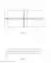
FIG. 1 shows a schematic representation of a radome according to the invention,
FIG. 2 shows a sectional representation of the radome,
FIG. 3 shows a schematic representation of a further exemplary embodiment, and
FIG. 4 shows an exploded representation of the radome as shown in FIG. 3 with a front panel.
PREFERRED EMBODIMENT OF THE INVENTION
FIG. 1 shows a flexible printed circuit board 1, formed as a film 5, with a metallic structure 2. The film 5 is formed as substantially rectangular and has groove-like impressions 3, 4. The impressions 3, 4 are provided in various configurations. One of the impressions 4 runs through the film 5 from the top to the bottom in FIG. 1, from one longitudinal side 6 to the opposite longitudinal side 7. The other two impressions 3 run from one of the narrow sides 8, 9 in each case in the direction of the middle, but they do not extend as far as the middle.
The metallic structure 2 consists of linear metallic ridges, which may be produced from a sheet-like metallic structure, for example by etching.
This film 5 is coated by back-molding with a thermoplastic material 11. This can be seen in FIG. 2.
FIG. 2 shows a section of a radome 10, wherein a flexile printed circuit board 1, which is formed in particular as a film 5 and has a metallic structure 2. In a form given by way of example, the metallic structure 2 is provided by means of linear strips, but it may also be formed in other ways.
The flexible printed. circuit board 1 is hot-stamped and has impressions 3, 4, which cannot however be seen in FIG. 2. Furthermore, the flexible printed circuit board 1 is back-molded with a thermoplastic material 11. In this case, the back-molded plastic is applied on the side of the film 5 on which the metallic structure 2 is applied. The back-molded plastic in this case covers the metallic structure, at least in certain regions.
The film 5 is preferably a laminate film, such as in particular a metallized laminate film of plastic. In this case, the film is preferably a film that comprises PI, PEN or PC. Here, PI stands for polyimide, PC for polycarbonate and PEN for polyethylene naphthalate.
The metallization advantageously consists of copper, the metallized structure in particular being etched. Alternatively, the metallization may also consist of some other material, for example of aluminum or the like. The application of the structure may also be performed in. some other way.
To improve the adhesive bonding of the back-molded plastic 11 on the film 5, a predefined surface structure may be produced, such as for example by a pretreatment. As a result, a layer 12 that preferably serves for increased bonding with the back-molded plastic is created on the surface of the film. The surface structure may for example be obtained by stamping impressions into a surface layer of the liquid, adhesive-like component of the film.
FIG. 3 shows a further exemplary embodiment of a back-molded film 20. This film is back-molded with a thermoplastic material 21, which also projects beyond the film 20 at the edge 22. Incorporated terminal contacts 23 can also be seen, for the electrical contacting of the metallic structure, which cannot however be seen in FIG. 3.
FIG. 4 shows in a kind of exploded representation comprising a film 30 with metallization. This film is back-molded with a thermoplastic material and forms the element, shown on the left, of the film with back-molded plastic 31. A front panel 32 may be arranged on it. Furthermore, a connector 33 can also be seen, serving for the electrical connection of the heatable radome.
LIST OF DESIGNATIONS
1 flexible printed circuit board
2 metallic structure
3 impression
4 impression
5 film
6 longitudinal side
7 longitudinal side
8 narrow side
9 narrow side
10 radome
11 back-molded plastic
12 layer
20 back-molded film
21 thermoplastic material
22 edge
23 terminal contact
30 film
31 film with hack-molded plastic
32 front panel
33 connector
Claims
1. A method for producing a heatable radome, wherein a flexible printed circuit board with a metallic structure is used and the flexible printed circuit board is stamped and back-molded with a thermoplastic material.
2. The method as claimed in claim 1, wherein the flexible printed circuit board consists of a flexible film that has a metallic structure.
3. The method as claimed in claim 2, wherein the film is a laminate film, such as in particular a metallized laminate film of plastic.
4. The method as claimed in claim 2, wherein the film comprises PI, PEN or PC.
5. The method as claimed in claim 1, wherein the thermoplastic material is back-molded on the side of the film with the metallic structure.
6. The method as claimed in claim 1, wherein the metallization consists of copper, the metallized structure in particular being etched.
7. The method as claimed in claim 1, wherein a predefined surface structure is created to improve the adhesive bonding of the back-molded plastic on the film.
8. The method as claimed in claim 7, wherein the surface structure is obtained by stamping impressions into a surface layer of the liquid, adhesive-like component of the film.
9. The method as claimed in claim 1, wherein the film is pre-stamped before the back-molding, such as in particular by hot stamping.
10. The method as claimed in claim 1, wherein the sheet-like plastic element thus created is connected to a front panel.
11. A radome consisting of a sheet-like plastic element with a metallized structure, wherein the plastic element consists of a film with back-molded thermoplastic material, the radome being heatable.
12. The radome as claimed in claim 11, wherein the plastic element is provided with a front panel.
Images & Drawings included:


Sources:
- United States Patent and Trademark Office - verify current appl. status at the USPTO↗
Similar patent applications:
Recent applications in this class:
- » 20230261369 2023-08-17
RADAR SENSOR - » 20210159593 2021-05-27
Electromagnetic-wave transmitting cover and door outer handle including same - » 20210159592 2021-05-27
Electromagnetic wave transmissive cover and method for manufacturing the same - » 20200373657 2020-11-26
Additively manufactured mesh cavity antenna - » 20200321695 2020-10-08
Metal space frame radome - » 20200295452 2020-09-17
Millimeter-wave radar cover - » 20200203820 2020-06-25
ANTENNA MODULE INCLUDING FILTER - » 20200153093 2020-05-14
Cover element - » 20180366821 2018-12-20
Dielectric-encapsulated wideband metal radome - » 20180287252 2018-10-04
Method for producing a radome and corresponding radome
Recent applications for this Assignee:
- » 20250224009 2025-07-10
ELECTROMECHANICAL SPREADER DEVICE FOR A DRUM BRAKE - » 20250215949 2025-07-03
DAMPING ELEMENT AND RETAINING SYSTEM FOR A VEHICLE - » 20250179955 2025-06-05
COOLANT DISTRIBUTION SYSTEM, METHOD OF MANUFACTURING - » 20250153565 2025-05-15
SHORT-STROKE INDUCTIVE SENSOR - » 20250147139 2025-05-08
OPTIMIZED ANGLE OF ARRIVAL (AoA) DETERMINATION - » 20250146346 2025-05-08
VEHICLE WITH MULTIMODAL TRUNK LID - » 20250138184 2025-05-01
VEHICLE AND METHOD FOR PRECIPITATION DETECTION - » 20250138181 2025-05-01
VEHICLE AND METHOD FOR VEHICLE COUNTING - » 20250130608 2025-04-24
DAMPER FOR A PEDAL OF A VEHICLE, PEDAL HAVING A DAMPER OF THIS TYPE, AND SYSTEM - » 20250130124 2025-04-24
METHOD FOR CONSTRUCTING A FORCE SENSOR GROUP, AND FORCE SENSOR GROUP FOR A MOTOR VEHICLE