Stator for electric machine
US20180269730A1
2018-09-20
15/762,115
2016-10-06
✅ Patent granted
US 10,541,572 B2
2020-01-21
WO; PCT/BG2016/000024; 20161006
WO; WO2017/059503; 20170413
Naishadh N Desai
Brown & Michaels, PC
2036-10-06
Abstract:
The stator is used for realization of drives and for generation electric energy in various fields of engineering. It provides reduction of basic and added electric losses in the stator winding at increased power. The stator includes a cylindrical stator pack (1) with a plurality of uniformly distributed slots (2) with an opening on the inner surface of the stator. In the slots (2) are laid double-layer winding composed of one or more than one double-arm sections (4) of wires having a rectangular cross-section, comprising an arm (5) adjacent to opening and an arm (6) to bottom of the slot (2), laid in two slots (2) distant from each other in step Y. The slot (2) is rectangular in one or two stages. The size (b1) in the radial direction of the cross-section of the wire, building at least one elementary double-arm section of the arm (5) near to an opening is at most equal to the size (b) in a radial direction of other wires in the slot (2).
Assignee:
- ALMOTT OOD 1 🇧🇬 Stara Zagora, Bulgaria
Applicant:
Interested in similar patents?
Get notified when new applications in this technology area are published.
Classification:
H02K1/165 » CPC main
Details of the magnetic circuit characterised by the shape, form or construction; Stationary parts of the magnetic circuit; Stator cores with slots for windings Shape, form or location of the slots
H02K3/345 » CPC further
Details of windings; Windings characterised by the shape, form or construction of the insulation between conductors or between conductor and core, e.g. slot insulation between conductor and core, e.g. slot insulation
H02K3/12 » CPC further
Details of windings; Windings characterised by the conductor shape, form or construction, e.g. with bar conductors arranged in slots
H02K1/16 IPC
Details of the magnetic circuit characterised by the shape, form or construction; Stationary parts of the magnetic circuit Stator cores with slots for windings
H02K3/34 IPC
Details of windings; Windings characterised by the shape, form or construction of the insulation between conductors or between conductor and core, e.g. slot insulation
Description
FIELD OF THE INVENTION
The present invention relates to a stator for electric machine that is primarily intended to work as an alternator, motorgenerator, traction motor and generator for electric vehicles, electric motor for spindle drives and servodrives for machine tools with CNC, multipolar high-speed generator.
PRIOR ART
It is known stator for electric machine [1] including cylindrical stator pack on the inner surface thereof a multitude of uniformly distributed slots covered by electric insulation and with an opening are formed. One or more double-layer windings are laid consisting of double-arm sections. The double-arm sections being formed by at least one elementary double-arm section made of wire with rectangular cross-section. The double-arm sections include an arm located to the opening, and an arm located to the bottom of the slot. The arm, located to the opening and the arm located to the bottom of each elementary double-arm section are laid in two slots distant from each other in step Y. In case of more than two elementary double-arm sections a part of the elementary double-arm sections has different size in a tangential direction of the cross-section of the wires. The shape of the slots is barrel-shaped following the widths of the wires of the double-arm sections. In case of a larger number of wires, the slots have a cross-section comprising two barrel-shaped forms, one above the other and joined together.
A disadvantage of the known stator is that because of the barrel shape of the slots, the increase in the cross-section of the wirers of the slots in the direction to the bottom is limited, whereby the reduction of electric and added losses in the stator winding is limited and so the increase of power of the electric machine is limited too.
SUMMARY OF THE INVENTION
An aim of the invention is to create a stator for electric machine with reduced electric and added losses and increased power.
This aim is solved by stator for electric machine including a cylindrical stator pack, on the inner surface of which is formed a plurality of uniformly distributed slots with an opening and covered with electric insulation. In the slots are laid double-layer windings composed of double-arm sections comprising at least one elementary double-arm section, made of wire with rectangular cross-section. The two arms of the double-arm section are laid in slots, distant from each other in step Y. According to the invention, the slot has at least one stage with a rectangular cross-section, and the size in the radial direction of the cross-section of a portion of the wires in a slot including also a wire disposed to the opening of the slot is smaller than the size in the radial direction of the cross-section of the rest of the wires in the same slot.
It is possible for the slot to be with a two-stage rectangular cross-section, and the opening of the slot is located in the stage with a smaller width.
It is possible that the dimensions in the radial direction of the cross-section of the rectangular wires located in the stage with the smaller width of the slot to be smaller than the dimensions of the cross-section of the wire in the radial direction located in the stage with a greater width.
It is possible the double-arm section to be shaped like a hairpin split open.
It is also possible the double-arm section to be formed by two soldered wires by soldering their parts before entering the slots.
It is possible that the dimensions in the radial direction of the cross-section of the wires to an opening of a slot and a bottom of a slot in their rear parts prior to entering the slot, to be greater than the size in the radial direction of the cross-section of the front parts to the soldered joints between the double-arm sections and of the parts of the same wires in a slot.
It is possible that each wire of an elementary double-arm section arm to have the same cross-sections all along its stretch.
An advantage of the stator for electric machine according to the invention is that both the basic and added electric losses of the stator winding are reduced, and the power is increased without increasing the depth of the slots. This is due to the reduced dimension in the radial direction of the cross-section of the slot portion of the wire/wires located to an opening of a slot, which provides a strong reduction of the added electric losses in these wires, which are substantially larger. At that their increased resistance is compensated by increased dimensions in the radial direction of the wires located closer to the bottom of the slots, where the added electric losses are substantially smaller.
BRIEF DESCRIPTION OF THE DRAWINGS
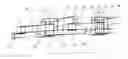
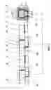
FIG. 1 is a perspective view from the side of the soldered joints of the double-arm sections made up of one elementary double-arm section, shaped like a hairpin split open, with two partial cutouts of the stator pack, each comprising a slot with a rectangular cross-section, distant in step Y, in each slot were laid one arm at the side by opening of one double-arm section and one arm to the bottom of the next double-arm section.
FIG. 2 is a view from the side of the soldered joints of the double-arm sections of the embodiment shown in FIG. 1, one cutout of the stator pack is shown as a cross-section through the cutout of the one slot with the wires laid therein.
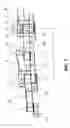
FIG. 3 is a view from the side of the soldered joints of the double-arm sections in the embodiment shown in FIGS. 1 and 2 with three partial cutouts of the stator pack, wherein the one cutout of the stator pack is shown as a cross-section through the one slot with the wires laid therein.
FIG. 4 is a view from the side of the soldered joints of the double-arm sections made up of more than one elementary section, formed as hairpins split open, with three partial cutouts of the stator pack, one cutout of the stator pack is shown as a cross-section through the cutout of the one slot with the wires laid therein.
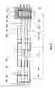
FIG. 5 is a view from the side of the soldered joints of two windings from double-arm sections arranged one over the other, shaped like hairpins split open, with three partial cutouts of the stator pack, one cutout of the stator pack is shown as a cross-section through the cutout of the one slot with the wires laid therein.
FIG. 6 is a view from the side of the soldered joints of the double-arm sections made up of one elementary double-arm section, formed by soldered joint, with three partial cutouts of the stator pack, one cutout of the stator pack is shown as a cross-section through the cutout of the one slot with the wires laid therein.
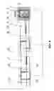
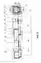
FIG. 7 is a view from the side of the soldered joints of the double-arm sections made up of an elementary double-arm section each, formed by soldered joint, with three partial cutouts of the stator pack, one cutout of the stator pack is shown as a cross-section through the cutout of the one slot with the wires laid therein.
FIG. 8 is a view from the side of the soldered joints of the double-arm sections made up of an elementary double-arm section each, formed by soldering, with three partial cutouts of the stator, one cutout of the stator pack is shown as a cross-section through the cutout of the one slot with the wires laid therein.
FIG. 9 is a view from the side of the soldered joints of two windings from double-arm sections arranged one above the other, shaped like hairpins split open, with three partial cutouts of the stator pack, one cutout of the stator pack is shown as a cross-section through the cutout of the one slot with the wires laid therein.
DETAILED DESCRIPTION OF PREFERRED EMBODIMENTS
In an preferred embodiment shown on FIG. 1 and FIG. 2 the stator for electric machine according to the invention is shown, comprising a cylindrical stator pack I made of electric sheets, on the inner surface of which is formed a plurality of uniformly distributed slots 2 with an opening and single rectangular cross-section. The slots 2 are covered with electric insulation 3. In each of the slots 2 is laid double-layer winding composed of double-arm sections 4. Each double-arm section 4 is composed of an elementary double-arm section, which is shaped as a hairpin split open from wire with a rectangular cross-section. The double-arm section 4 comprises an arm 5, adjacent to opening, and an arm 6 arranged to the bottom of the slot 2. The arm 5 adjacent to opening has a front end portion 51 and a rear end portion 52. The arm 6 positioned at the bottom of the slot 2 has a front end portion 61 and rear end portion 62. In the double-layer winding front end portions 51 and 61 of the double-arm sections 4 are soldered to one another by soldered joints 7. The arm 5 adjacent the opening of the slot, and the arm 6 positioned at the bottom of the slot of each elementary double-arm section 4 are laid in two slots 2, distant from each other in step Y. The size a1 in the tangential direction of the wire cross-section of the arm 5 and the size a2 in the tangential direction of the wire cross-section of the arm 6 are equal. The size b1 in the radial direction of the wire cross-section in the slot part and the front part 51 of the arm 5, adjacent an opening, is less than the size b2 in the radial direction of the wire cross-section of the rear end parts 52 and 62, of the slot part of the rear arm 6 and of the front part 61.
The same embodiment is shown in FIG. 3 and is characterized in that it shows three cutouts of the stator pack 1 around the slot 2, one cutout of the stator pack 1 is shown as a cross-section through the cutout of the one slot 2 with the wires laid therein.
The further exemplary embodiment shown in FIG. 4 differs from the embodiment shown in FIGS. 1, 2 and 3 in that the double-arm section 4 is comprised of more than one elementary double-arm sections: enveloping 8 and enveloped 9 formed as hairpins split open. The dimensions 85b1 and 86b2 in the radial direction of the cross-section of the arms wires of the enveloping elementary section 8 comprising the arm 85 adjacent an opening are smaller than the dimensions 96b1 and 96b2 in the radial direction of the cross-section of the arms wires 95 and 96 of enveloped elementary section 9. The dimensions in the radial direction of the cross-section of the wires of the enveloping 8 and enveloped 9 sections are equal in all their parts to the dimensions in the radial direction of the cross-section of wires in their slot parts. In the double-layer winding double-arm sections 4 are soldered to one another by soldered joints 7.
In the next preferred embodiment shown in FIG. 5 are shown double-arm sections 4A and 4B, realized as hairpins split open, forming windings arranged one above the other. The dimensions in the radial direction A5b1 and A6b2 of the cross-sections of the wires composing the lying to the opening of the slot double-arm sections 4A are equal to each other and are smaller than the dimensions in the radial direction V5b1 and V6b2 of the cross-sections of the wires composing the lying to slot bottom double-arm sections 4B. The dimensions in the radial direction of the cross-section of the wires of the double-arm windings 4A and 4B in all their parts are equal to the dimensions in the radial direction of the cross-section of the wires in their slot parts. The double-arm sections 4A are joined in a winding by soldered joints A7. Double-arm sections 4B are joined in a winding by soldered joints B7. There is no difference among the dimensions of cross-sections of the wires in different parts of sections A. Also there is no difference among the dimensions of cross-sections of the wires in different parts of sections B.
The next embodiment shown in FIG. 6, differs from the embodiment shown in FIGS. 1, 2 and 3 in that the double-arm section 4 is formed by soldered joints 10 of the rear part 52 of the arm 5, situated next to the slot opening, and the rear part 62 of the arm 6 positioned at the slot bottom and in that the dimensions of the wire cross-section of the arm 5 in all its parts are identical with each other, and the dimensions of the wire cross-section of the arm 6 in all its parts are identical with each other. The size b1 in the radial direction of the wire cross-section of the arm 5 is less than the size b2 in the radial direction of the wire cross-section of the arm 6. In the double-layer winding front end parts 51 and 61 of the double-arm sections 4 are soldered by soldered joints 7.
In FIG. 7 is shown a further embodiment of the invention, which differs from the embodiment shown in FIG. 6 in that the cross-section of the slot 2 is a two-stage rectangular section, formed of two rectangular parts with different widths which are connected to one another and are arranged one above the other. The opening of the slot 2 is located in the part with a smaller width. In the slots 2 is laid a double-layer winding built of soldered double-arm sections 4. The rear part 52 of the arm 5 and 62 of the arm 6 are soldered to one another by soldered joints 10. The arm 6 has a greater width a2 of the cross-section of the wire and situated in the part of the slot 2 with a greater width to slot bottom. The arm 5 adjacent the opening has a smaller width a1 of the wire cross-section and is placed in a part with a smaller width to the opening of the slot 2. Size b1 in the radial direction of the wire cross-section of the arm 5, situated to slot opening is smaller than the size b2 in the radial direction of the wire cross-section of the arm 6 to slot bottom. The dimensions of the cross-sections of the parts of the arm 5 are equal to each other. The dimensions of the cross-sections of the parts of the arm 6 are equal to each other. The arms of the double-arm sections 4 are distant from each other in step Y. Double-arm sections 4 were joined in a winding through soldered joints 7 between their front end parts.
The further exemplary embodiment shown in FIG. 8, differs from the embodiment shown in FIG. 7, in that the size 52b in the radial direction of the wire cross-section of the rear end part 52 of arm 5 is greater than the size of arm 5 in the radial direction of the cross-section of the wires of its slot part b1 and its front end part 51b. Also, the size 62b in the radial direction of the wire cross-section of the rear end part 62 of the arm 6 is greater than the dimensions of its slot part b2i and of its front end part 61b.
The next exemplary embodiment shown in FIG. 9, is analogous to the embodiment shown in FIG. 5, and differs from it in that the rectangular cross-section of the slots 2 is two-stage and is formed of two rectangular parts of different widths, joined to one another and arranged one above another, the narrower parts of the slots 2 are next to the openings. The size a2 in the tangential direction of the cross-section of the wires of the arms of the sections 4B is larger than the size a1 in the tangential direction of the wires cross-section of the arms of the sections 4A. The dimensions A5b1 and A6b2 in the radial direction of the cross-section of the arms of the sections 4A are equal to each other and are smaller than the dimensions B5b1 and B6b2 in a radial direction of the wires cross-section of the arms of the sections 4B, which are also equal to each other. Sections 4A are joined in a winding by soldered joints A7. Sections 4B are joined in a winding by soldered joints B7.
Use of the Invention
The stator for electric machine according to the invention is used mounted in the electric machine comprising a rotor mounted on a shaft. The drive shaft is sustained by bearings in front and rear end bells. By current flowing in the stator winding, the magnetic field created by this current, reacts with an existing or created magnetic field of the rotor, with the result that torque arises. By the reduction of size b in the radial direction of the cross-section of the one or more wires arranged to the openings of the slots 2 are reduced also the generated added electric losses by leakage alternating magnetic field in the slots 2, running through the wires, which is most intensive in the area near to the openings of the slots 2. At the same time, the increase in basic electric losses due to increased active resistance of the wires with reduced dimensions b1 of their cross-sections is offset by reduced active resistance of the other wires in the slots 2 due to the larger dimensions b2 in the radial direction of their cross-sections. As a result, the value of the added electric losses is reduced. The value of basic electric losses in the winding as a whole is maintained or reduced. As a result of application of the invention, the total electric losses are reduced and the power of the electric machine is increased.
Experimental Results Received During Experimentation of the Invention
According to the invention was developed a version of an existing virtual competitive model of an existing stator of electric machine with the following characteristic data: number of wires in the slot 2, dimensions of the cross-section of the wires 2.5+4.5 mm., number of slots 72 and number of poles 12, length of the stator pack 55 mm. The comparison is made for speed 6000 RPM.
The virtual sample according to developed version has stator pack fully equal in size to the stator pack of the existing model. The dimensions of the cross-sections of the wires in the virtual sample are modified as follows: dimensions of the cross-section of the wires to the slot opening: 2.5+3.5 mm, dimensions of the cross-section of the wires to the slot bottom: 2.5+5.5 mm. The amount of basic and added electric losses of the virtual sample is reduced by 25% compared to the amount of basic and added electric losses of the existing model.
REFERENCE
1. Bulgarian Patent Application No 111369 filed on 19 Dec. 2012
Claims
1. Stator for electric machine comprising a cylindrical stator pack, on the inner surface of which is formed a plurality of uniformly distributed slots covered with electric insulation and with an opening, in the slots are laid double-layer windings composed of double-arm sections containing at least one elementary double-arm section, made of wire with rectangular cross-section, at that the two arms of a double-arm section are laid in slots, distant from each other in step Y, characterized in that the slot (2) has a rectangular cross-section with at least one stage, and the size (b1) in the radial direction of the cross-section of a part of the wires in a slot, including the wire adjacent to slot opening is smaller than the size (b2) in the radial direction of the cross-section of the rest of the wires in the slots (2).
2. Stator according to claim 1, wherein the slot (2) with a rectangular cross-section is a two-stage, the opening of the slot (2) is arranged in the stage of lesser width (a1).
3. Stator according to claim 2, wherein the dimensions (b1) in the radial direction of the cross-section of rectangular wires located in the stage with the smaller width of the slot (2) are smaller than the dimensions (b2) in the radial direction of the cross-section of the wires located at the stage of greater width.
4. Stator according to one of claims 1 to 3, wherein the double-arm section (4) is shaped like a hairpin split open.
5. Stator according to one of claims 1 to 3, wherein the double-arm section (4) is formed by two soldered wires through soldered joints (10) in their part before entering the slots (2).
6. Stator according to one of claims 1 to 5 wherein the dimensions (b) in a radial direction of the cross-section of the wires to slot opening and to slot bottom in their rear parts (52, 62) prior to entering the slot (2) are larger than the dimensions (b) in a radial direction of the cross-section of the front part (51 and 61) to the soldered joints (7) between the double-arm sections (4) and of the parts in a slot of the same wires.
7. Stator according to one of c claims 1 to 5, wherein each wire of the arm of the elementary section has the same cross-section along its entire length.
Images & Drawings included:


Sources:
- United States Patent and Trademark Office - verify current appl. status at the USPTO↗
Similar patent applications:
- » 20160156240
Stator winding for rotary electric machine, stator for rotary electric machine, method of manufacturing stator for rotary electric machine, and jig used in manufacturing stator for rotary electric machine - » 20210111598
ELECTRIC-MACHINE STATOR LAMINATION, ELECTRIC-MACHINE STATOR IRON CORE AND ELECTRIC MACHINE - » 20180351417
ROTATING ELECTRIC MACHINE STATOR, ROTATING ELECTRIC MACHINE, AND METHOD FOR MANUFACTURING ROTATING ELECTRIC MACHINE STATOR - » 20170346358
Rotary-electric-machine stator coil, rotary-electric-machine stator having the same, and rotary electric machine having the same - » 20150155760
Rotary electric machine with a pair of interfitting portions, rotary electric machine stator, and rotary electric machine stator manufacturing method - » 20240275219
STATOR CORE OF ROTATING ELECTRIC MACHINE, STATOR OF ROTATING ELECTRIC MACHINE, ROTATING ELECTRIC MACHINE, METHOD FOR MANUFACTURING STATOR CORE OF ROTATING ELECTRIC MACHINE, AND METHOD FOR MANUFACTURING ROTATING ELECTRIC MACHINE - » 20210036569
Rotating electrical machine stator and method for manufacturing rotating electrical machine stator - » 20250023402
METHOD FOR MOUNTING A DECOUPLING ELEMENT IN A THROUGH-HOLE IN A STATOR OF AN ELECTRIC MACHINE, STATOR FOR AN ELECTRIC MACHINE, AND ELECTRIC MACHINE COMPRISING A STATOR OF THIS TYPE - » 20230109194
Method for manufacturing stator of rotating electric machine, stator of rotating electric machine, and rotating electric machine - » 20220416630
Method for manufacturing stator of rotating electrical machine, stator of rotating electrical machine, and rotating electrical machine
Recent applications in this class:
- » 20250260273 2025-08-14
ROTARY ELECTRIC MACHINE - » 20250260272 2025-08-14
STATOR CORE AND STATOR FOR AN AXIAL FLUX ROTATING ELECTRIC MACHINE - » 20250253720 2025-08-07
STATOR AND MOTOR - » 20250246950 2025-07-31
DOUBLY SALIENT PARALLEL PATH MAGNETIC MOTOR - » 20250239898 2025-07-24
MAGNETIC CORE, COIL-EQUIPPED MAGNETIC CORE, ROTATING ELECTRICAL MACHINE, AND BRUSHLESS MOTOR - » 20250233465 2025-07-17
STATOR - » 20250219479 2025-07-03
MAGNETIC CORE, STATOR ASSEMBLY, ROTATING ELECTRICAL MACHINE, AND BRUSHLESS MOTOR - » 20250211039 2025-06-26
STATOR CORE FOR ELECTRIC MOTOR, ELECTRIC MOTOR, AND ELECTRIC MOTORCYCLE - » 20250202295 2025-06-19
STATOR FOR AN ELECTRIC MACHINE - » 20250192622 2025-06-12
STATOR CORE OF ROTARY ELECTRIC MACHINE