Systems and methods for a heat sink
US20180324980A1
2018-11-08
15/651,941
2017-07-17
✅ Patent granted
US 10,627,093 B2
2020-04-21
-
-
Gordon A Jones
Yutian Ling
2037-07-17
Abstract:
Embodiments may utilize a series of exposed fins, which increase the surface area of the heat sink creating additional air flow. As hotter air rises within the system, cooler is drawn into the heatsink. The fins may be exposed on both sides of the longitudinal axis, allowing cooler air to be drawn towards the longitudinal axis above the heatsink and flow upward. This process may cool the fins. Additionally, the spacing between the fins may have to be wide enough to allow for air to freely enter the heatsink.
Inventors:
- Nicholas Klase 16 🇺🇸 Austin, TX, United States
- Randall Johnson 20 🇺🇸 Austin, TX, United States
- Dung Duong 20 🇺🇸 Austin, TX, United States
Assignee:
- Fluence Bioengineering, Inc. 54 🇺🇸 Austin, TX, United States
Applicant:
Interested in similar patents?
Get notified when new applications in this technology area are published.
Classification:
H05K7/20409 » CPC main
Constructional details common to different types of electric apparatus; Modifications to facilitate cooling, ventilating, or heating characterised by the heat transfer by conduction from the heat generating element to a dissipating body Outer radiating structures on heat dissipating housings, e.g. fins integrated with the housing
H05K7/20 IPC
Constructional details common to different types of electric apparatus Modifications to facilitate cooling, ventilating, or heating
H05K7/20 IPC
Constructional details common to different types of electric apparatus Modifications to facilitate cooling, ventilating, or heating
F21V29/76 » CPC further
Protecting lighting devices from thermal damage; Cooling or heating arrangements specially adapted for lighting devices or systems; Cooling arrangements characterised by passive heat-dissipating elements, e.g. heat-sinks with fins or blades with essentially identical parallel planar fins or blades, e.g. with comb-like cross-section
H05K1/05 » CPC further
Printed circuits; Details; Use of materials for the substrate Insulated conductive substrates, e.g. insulated metal substrate
H05K1/05 » CPC further
Printed circuits; Details; Use of materials for the substrate Insulated conductive substrates, e.g. insulated metal substrate
F21V29/763 » CPC further
Protecting lighting devices from thermal damage; Cooling or heating arrangements specially adapted for lighting devices or systems; Cooling arrangements characterised by passive heat-dissipating elements, e.g. heat-sinks with fins or blades with essentially identical parallel planar fins or blades, e.g. with comb-like cross-section the planes containing the fins or blades having the direction of the light emitting axis
F21V29/74 IPC
Protecting lighting devices from thermal damage; Cooling or heating arrangements specially adapted for lighting devices or systems; Cooling arrangements characterised by passive heat-dissipating elements, e.g. heat-sinks with fins or blades
H05K1/02 IPC
Printed circuits Details
H05K1/02 IPC
Printed circuits Details
H05K1/021 » CPC further
Printed circuits; Details; Thermal arrangements, e.g. for cooling, heating or preventing overheating; Cooling of mounted components Components thermally connected to metal substrates or heat-sinks by insert mounting
H05K1/021 » CPC further
Printed circuits; Details; Thermal arrangements, e.g. for cooling, heating or preventing overheating; Cooling of mounted components Components thermally connected to metal substrates or heat-sinks by insert mounting
H01L23/367 » CPC further
Details of semiconductor or other solid state devices; Arrangements for cooling, heating, ventilating or temperature compensation ; Temperature sensing arrangements; Selection of materials, or shaping, to facilitate cooling or heating, e.g. heatsinks Cooling facilitated by shape of device
F21V23/009 » CPC further
Arrangement of electric circuit elements in or on lighting devices the elements being electronics drivers or controllers for operating the light source, e.g. for a LED array enclosed in a casing the casing being inside the housing of the lighting device
H05K3/0061 » CPC further
Apparatus or processes for manufacturing printed circuits; Laminating printed circuit boards onto other substrates, e.g. metallic substrates onto a metallic substrate, e.g. a heat sink
H05K3/0061 » CPC further
Apparatus or processes for manufacturing printed circuits; Laminating printed circuit boards onto other substrates, e.g. metallic substrates onto a metallic substrate, e.g. a heat sink
F21V19/0055 » CPC further
Fastening of light sources or lamp holders the light sources being semiconductors devices, e.g. LEDs; Fastening of light source holders, e.g. of circuit boards or substrates holding light sources by screwing
F21W2131/40 » CPC further
Use or application of lighting devices or systems not provided for in codes - Lighting for industrial, commercial, recreational or military use
F21V29/502 » CPC main
Protecting lighting devices from thermal damage; Cooling or heating arrangements specially adapted for lighting devices or systems; Cooling arrangements characterised by the adaptation for cooling of specific components
A01G9/20 » CPC further
Cultivation in receptacles, forcing-frames or greenhouses ; Edging for beds, lawn or the like Forcing-frames; Lights, i.e. glass panels covering the forcing-frames
F21V29/745 » CPC further
Protecting lighting devices from thermal damage; Cooling or heating arrangements specially adapted for lighting devices or systems; Cooling arrangements characterised by passive heat-dissipating elements, e.g. heat-sinks with fins or blades the fins or blades being planar and inclined with respect to the joining surface from which the fins or blades extend
F21V29/75 » CPC further
Protecting lighting devices from thermal damage; Cooling or heating arrangements specially adapted for lighting devices or systems; Cooling arrangements characterised by passive heat-dissipating elements, e.g. heat-sinks with fins or blades with fins or blades having different shapes, thicknesses or spacing
F21V29/83 » CPC further
Protecting lighting devices from thermal damage; Cooling or heating arrangements specially adapted for lighting devices or systems; Cooling arrangements characterised by passive heat-dissipating elements, e.g. heat-sinks the elements having apertures, ducts or channels, e.g. heat radiation holes
F28F3/02 » CPC further
Plate-like or laminated elements; Assemblies of plate-like or laminated elements Elements or assemblies thereof with means for increasing heat-transfer area, e.g. with fins, with recesses, with corrugations
A01G9/26 » CPC further
Cultivation in receptacles, forcing-frames or greenhouses ; Edging for beds, lawn or the like; Devices for heating, ventilating, regulating temperature , or watering, in greenhouses, forcing-frames, or the like Electric devices
F21V29/67 » CPC further
Protecting lighting devices from thermal damage; Cooling or heating arrangements specially adapted for lighting devices or systems; Cooling arrangements characterised by the use of a forced flow of gas, e.g. air characterised by the arrangement of fans
F21Y2103/10 » CPC further
Elongate light sources, e.g. fluorescent tubes comprising a linear array of point-like light-generating elements
F21Y2115/10 » CPC further
Light-generating elements of semiconductor light sources Light-emitting diodes [LED]
F28D2021/0029 » CPC further
Heat-exchange apparatus not covered by any of the groups - ; Other heat exchangers for particular applications; Heat exchange systems not otherwise provided for for cooling heat generating elements, e.g. for cooling electronic components or electric devices Heat sinks
F28F3/025 » CPC further
Plate-like or laminated elements; Assemblies of plate-like or laminated elements; Elements or assemblies thereof with means for increasing heat-transfer area, e.g. with fins, with recesses, with corrugations the means being corrugated, plate-like elements
F21V23/00 IPC
Arrangement of electric circuit elements in or on lighting devices
H05K3/00 IPC
Apparatus or processes for manufacturing printed circuits
H05K3/00 IPC
Apparatus or processes for manufacturing printed circuits
F28D21/00 IPC
Heat-exchange apparatus not covered by any of the groups -
F21V19/00 IPC
Fastening of light sources or lamp holders
Description
CROSS-REFERENCE TO RELATED APPLICATIONS
This application claims a benefit of priority under 35 U.S.C. §119 to Provisional Application No. 62/500945 filed on May 3, 2017, which is fully incorporated herein by reference in their entirety.
BACKGROUND INFORMATION
Field of the Disclosure
Examples of the present disclosure are related to systems and methods for a heat sink. More particularly, embodiments disclose a heat sink configured to dissipate heat caused by a light fixture, wherein the heat sink includes exposed fins that allow for additional air flow.
Background
Greenhouses are buildings or complexes in which plants are grown. For various reasons including price, it is typically ideal for greenhouses to operate with as much natural sunlight as possible. To supplement natural light from the sun, high powered lights are used within greenhouses when the sun or other natural light does not provide enough light for optimal plant growth.
However, the operation of the high powered lights is more costly than utilizing free sunlight. More so, conventional high powered lights are larger in size, which blocks the incoming free sunlight. Furthermore, the blocking of the incoming sunlight causes shading on the plants within the greenhouse, which negatively impacts the grower's productivity.
Although light emitting diodes (LEDs) are more efficient than traditional high powered lights, their manufacturing costs are higher. Additionally, the LEDs cause excessive shading based on requiring larger fixtures to dissipate heat. To circumvent the large fixtures required to dissipate the heat, some manufacturers have attempted to build smaller LED fixtures that use active cooling fans. However, in greenhouse environments, active cooling fans quickly clog with dirt, bugs, etc. This causes the LED fixtures with active cooling fans to quickly become inoperable.
Conventional LED fixtures that do not include active cooling fans use traditional linear heat sinks. However, traditional linear heat sinks include wings that extend in a direction parallel with a central axis of the conventional LED fixtures. Heat generated through conventional LED fixtures may dissipate based on convection, conduction or radiation. However, due to LED fixtures being suspended, there is minimal heat dissipation via conduction. Radiation is a function of the fixture temperature and may be significant, and convection is the primary method to dissipate heat. In applications, air particles remove heat from the fixture through air movement. For longer heat sinks, air movement within the middle of the fixtures is minimal. This severely limits the amount of power conventional LED fixtures can consume because additional power consumption leads to more heat.
Accordingly, needs exist for more effective and efficient systems and methods for heat sinks with exposed fins allowing for additional air flow.
SUMMARY
Embodiments disclosed herein describe systems and methods for heat sinks within light fixtures. In embodiments, a heat sink may be a passive system that continually and passively creates a cross-flow thermal management system dissipating large amounts of heat in a slim light fixture.
Embodiments may utilize a series of exposed fins that increase the surface area of the heat sink creating additional air flow. As hotter air rises within the system, cooler is drawn into the heatsink. The fins may have exposed sides, lower surface, and upper surface, allowing cooler air to be drawn towards the longitudinal axis above the light source and flow upward. This process may cool the fins. Additionally, the spacing between the fins may be wide enough to allow for air to freely enter the heatsink.
Embodiments may include systems having top extrusions to create the plurality of fins from an aluminum block. By creating the plurality of fins via extrusions and directly coupling the base or MCPCB to the fins, no secondary operations may be required to create the heat sink.
Embodiments may include extruded aluminum to create the plurality of fins, wherein a rib is formed along the longitudinal axis of the heat sink. The extrusions and/or rib may be textured and/or contoured in the heat flow direction. This may increase the surface area of the fins and rib exposed in the heat flow direction, allowing for a more efficient system.
The rib may extend vertically through the center of the plurality of fins. The vertical rib may be configured to pull heat away from a base and/or lower portions of the fins. Additionally, the base may not cover the entirety of a lower surface of the extruded fins. This may allow for more surface area of the fins to be exposed to manage heat flow. The base may include angled overhang that project away from the longitudinal axis of the base at a downward angle, further exposing the lower surfaces of the fins.
Embodiments may include MCPCB base that is directly attached to extruded fins with a rib extending along the central axis of the heat sink. This may allow for lower thermal resistance from heat sources to the fins, while also having less interfaces and/or coupling points. This may lead to a lower probability of air bubbles.
These, and other, aspects of the invention will be better appreciated and understood when considered in conjunction with the following description and the accompanying drawings. The following description, while indicating various embodiments of the invention and numerous specific details thereof, is given by way of illustration and not of limitation. Many substitutions, modifications, additions or rearrangements may be made within the scope of the invention, and the invention includes all such substitutions, modifications, additions or rearrangements.
BRIEF DESCRIPTION OF THE DRAWINGS
Non-limiting and non-exhaustive embodiments of the present invention are described with reference to the following figures, wherein like reference numerals refer to like parts throughout the various views unless otherwise specified.
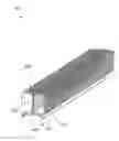
FIG. 1 depicts a cross flow heat sink, according to an embodiment.
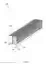
FIG. 2 depicts heat flow from the heat source through the fins, according to an embodiment.
FIG. 3 illustrates a method for a heat sink with a rib, according to an embodiment.
Corresponding reference characters indicate corresponding components throughout the several views of the drawings. Skilled artisans will appreciate that elements in the figures are illustrated for simplicity and clarity and have not necessarily been drawn to scale. For example, the dimensions of some of the elements in the figures may be exaggerated relative to other elements to help improve understanding of various embodiments of the present disclosure. Also, common but well-understood elements that are useful or necessary in a commercially feasible embodiment are often not depicted in order to facilitate a less obstructed view of these various embodiments of the present disclosure.
DETAILED DESCRIPTION
In the following description, numerous specific details are set forth in order to provide a thorough understanding of the present embodiments. It will be apparent, however, to one having ordinary skill in the art that the specific detail need not be employed to practice the present embodiments. In other instances, well-known materials or methods have not been described in detail in order to avoid obscuring the present embodiments.
Embodiments may utilize a series of exposed fins that increase the surface area of the heat sink creating additional air flow. The fins may be exposed on both sides of the longitudinal axis of the heat sink, allowing cooler air to be drawn internally towards the longitudinal axis of the heatsink, above the heat source, and flow upward. This process may cool the fins. Additionally, the spacing between the fins may be wide enough to allow for air to freely enter the heatsink via the sides of the fins and/or through exposed lower surfaces of the fins.
FIG. 1 depicts a cross flow heat sink 100, according to an embodiment.
Cross flow heat sink 100 may be configured to dissipate heat from a heat source, such as a light fixture, wherein the light fixture may be positioned under heat sink 100. In a conventional linear heat sink, the heat generated from the heat source flows around the heat sink. In cross flow heat sink 100, the generated heat may be configured to flow through spaces between fins 110, 120. This may more rapidly and efficiently dissipate the generated heat. Heat sink 100 may include fins 110, 120, rib 130, and base 140.
Fins 110, 120 may be extrusions from a unitary block of metal, such as aluminum. Fins 110 may be positioned on a first side of rib 130, and fins 120 may be positioned on a second side of rib 130. Fins 110 may be created by extruding the unitary block of metal from an upper surface to the lower surface of the unitary block of metal. Fins 110, 120 may be created by extrusions across the entire height of the unitary block of metal, but only a partial width of the unitary block of metal. This may cause fins 110, 120 to have three exposed edges, and a fourth edge covered by rib 130.
Rib 130 may be a projection, sidewall, surface, extending from a lower surface of heat sink 100 to an upper surface of heat sink 100. Rib 130 may be created by not extruding the unitary block of metal across the entire width of the unitary block of metal. In embodiments, by not extruding the unitary block of metal along its central axis, rib 130 may be formed without an additional procedure. Rib 330 may be the result of extrusions not extending across the central axis of the unitary sheet of metal. To this end, rib 130 may be positioned along the central axis of heat sink 100, wherein a first set of fins 110 may be positioned on a first side of rib 130 and a second set of fins 120 may be positioned on a second side of rib 130. In embodiments, an upper surface of rib 130 may be flush and planar with upper surfaces of fins 110, 120, and a lower surface of rib 130 may be flush and planar with lower surfaces of fins 310, 320.
Rib 130 may be textured, contoured, etc. with channels, grooves, etc. this may assist in increasing the internal surface area of heat sink 100. By increasing the internal surface area of heat sink 100, more efficient air flow through heat sink 100 may be created. In embodiments, the textures, contours, etc. on rib 130 may be symmetrical or asymmetrical across or along the central axis.
Base 140 may be positioned on a lower surface of fins 110, 120 and rib 30.
Base 140 may be bonded to the lower surface of finds 310 via adhesives, welding, or any other coupling mechanisms. Base 140 may have a shorter width than that of fins 110, and 120. Thus, base 140 may not extend across the entire width of a lower surface of heat sink 100 By not extending across the entire lower surface of heat sink 100 the outer lower surfaces 112 of fins 110, 120 may be exposed and uncovered, while the internal lower surfaces of fins 110, 120 and a lower surface of rib 130 may be covered by base 140. This may allow hotter air to enter heat sink 100 without traveling to the outer most edge of fins 110, 120. Base 140 may be configured to form a continuous, planar, and covered surface along the lower surfaces of fins 110, 120 and rib 130. In embodiments, base 140 may be configured to couple multiple unitary blocks of metal together along the longitudinal axis of the heat sink 100. This may allow for a longer heat sink 100, which is coupled together along base 140
Protrusions 142 may be positioned at the outer edges of base 140. Protrusions 142 may be projections extending away from base 140. In embodiments, protrusions 142 may project at a downward angle, and may be configured to guide heated air into the heat sink 100 via the lower, exposed areas 112 of fins 110, 110.
As depicted in FIG. 2 it is desired to increase the heat flow from the heat source through the fins. By increasing the surface area of the heat sink 200 via the fins, as hotter air 230 rises cooler air is draw into the heatsink 200. The cooler air may cool the fins.
As depicted by air flow lines 230 in FIG. 2, heat generated by a heat source below the heat sink 200 may travel around an overhang and towards a central axis of the heat sink 200. The hotter air positioned proximate to the central axis may rise due to cooler air entering the hat sink via the fins. Due to the fins created by the extrusions, the hotter air may be able to travel laterally and vertically through the heat sink.
Furthermore, the heat sink may include a rib 210. Rib 210 may extend across the central axis of the heat sink. However, rib 210 may not extend across the entire height of the fins. Rib 210 may be formed by not extruding across the entire height of a unitary block of metal along the central axis of heat sink 200. Rib 210 may be formed by the un-extruded block of metal, wherein two fins are formed on both sides of rib 210 by fully extruding the entire height of unitary block of metal on both sides of rib 210.
Additionally, the upper surface 220 of the fins may be extruded to form contours, depressions, grooves, ridges, projections, etc. By having a non-planar upper surface 220, turbulences may be created. The turbulences may cause more efficient air flow through the fins and heat sink.
FIG. 3 illustrates a method 300 for a heat sink with a rib, according to an embodiment. The operations of method 300 presented below are intended to be illustrative. In some embodiments, method 300 may be accomplished with one or more additional operations not described, and/or without one or more of the operations discussed. Additionally, the order in which the operations of method 300 are illustrated in FIG. 3 and described below is not intended to be limiting.
At operation 310, air below the heat sink may be heated by a light fixture positioned directly below the heat sink.
At operation 320, the heated air may travel around angled protrusions on the base of the heat sink, wherein the ends of the angled protrusions is positioned between the rib and the ends of the fins.
At operation 330, the heated air may enter the heat sink via partially exposed lower surfaces of the fins, wherein the lower surface of the fins are partially exposed from the first end of the protrusions to outer edges of the fins.
At operation 340, the heated air may conduct upward from a position proximate to the central axis of the heat sink above the light source on both sides of the rib. As hot air rises, cooler air may be drawn into the heatsink. This process may cool the fins.
Although the present technology has been described in detail for the purpose of illustration based on what is currently considered to be the most practical and preferred implementations, it is to be understood that such detail is solely for that purpose and that the technology is not limited to the disclosed implementations, but, on the contrary, is intended to cover modifications and equivalent arrangements that are within the spirit and scope of the appended claims. For example, it is to be understood that the present technology contemplates that, to the extent possible, one or more features of any implementation can be combined with one or more features of any other implementation.
Reference throughout this specification to “one embodiment”, “an embodiment”, “one example” or “an example” means that a particular feature, structure or characteristic described in connection with the embodiment or example is included in at least one embodiment of the present invention. Thus, appearances of the phrases “in one embodiment”, “in an embodiment”, “one example” or “an example” in various places throughout this specification are not necessarily all referring to the same embodiment or example. Furthermore, the particular features, structures or characteristics may be combined in any suitable combinations and/or sub-combinations in one or more embodiments or examples. In addition, it is appreciated that the figures provided herewith are for explanation purposes to persons ordinarily skilled in the art and that the drawings are not necessarily drawn to scale.
The flowcharts and block diagrams in the flow diagrams illustrate the architecture, functionality, and operation of possible implementations of systems, methods, and computer program products according to various embodiments of the present invention. In this regard, each block in the flowcharts or block diagrams may represent a module, segment, or portion of code, which comprises one or more executable instructions for implementing the specified logical function(s). It will also be noted that each block of the block diagrams and/or flowchart illustrations, and combinations of blocks in the block diagrams and/or flowchart illustrations, may be implemented by special purpose hardware-based systems that perform the specified functions or acts, or combinations of special purpose hardware and computer instructions.
Claims
What is claimed is:1. A heat sink for a light fixture comprising:
a rib formed by not extruding a unitary block of metal;
first fins positioned on a first side of the rib, the first fins being formed by extruding the unitary block of metal from an upper surface of the unitary block of metal to a lower surface of the unitary block of metal on the first side of the rib;
second fins positioned on a second side of the rib, the second fins being formed by extruding the unitary block of metal from the upper surface of the unitary block of metal to the lower surface of the unitary block of metal on the second side of the rib.
2. The heat sink of claim 1, wherein the rib extends from the lower surface of the unitary block of metal to the upper surface of the unitary block of metal.
3. The heat sink of claim 1, wherein the first fins and the second fins include grooves.
4. The heat sink of claim 1, wherein the rib includes grooves.
5. The heat sink of claim 1, further comprising:
a base, the base being configured to cover portions of the lower surface of unitary block of metal.
6. The heat sink of claim 5, further comprising:
protrusions positioned on the distal ends of the base, the protrusions having a downward angle that partially expose the lower surfaces of the first fins and the second fins.
7. The heat sink of claim 6, wherein distal ends of the protrusions are positioned between outer edges of the first set of fins and the second set of fins and the distal ends of the base.
8. The heat sink of claim 5, wherein the base is configured to be directly coupled to multiple sections of the heat sink, each of the sections including the rib, the first set of fins, and the second set of fins, wherein the base is a MCPCB base.
9. The heat sink of claim 1, wherein the first set of fins and the second set of fins have three exposed edges, and a fourth edge being covered by the rib.
10. The heat sink of claim 1, wherein the upper surfaces of the first set of fins and the second set are fins are planar with an upper surface of the rib.
11. A method of forming a heat sink for a light fixture comprising:
forming a rib formed by not extruding portions of a unitary block of metal;
extruding the unitary block of metal from an upper surface of the unitary block of metal to a lower surface of the unitary block of metal on a first side of the rib to form first fins;
extruding the unitary block of metal from the upper surface of the unitary block of metal to the lower surface of the unitary block of metal on a second side of the rib to form second fins.
12. The method of claim 11, wherein the rib extends from the lower surface of the unitary block of metal to the upper surface of the unitary block of metal.
13. The method of claim 11, further comprising:
extruding grooves on the first fins and the second fins include grooves.
14. The method of claim 11, wherein the rib includes grooves.
15. The method of claim 11, further comprising:
coupling a base to portions of the lower surface of the unitary block of metal.
16. The method of claim 15, wherein the base includes protrusions positioned on the distal ends of the base, the protrusions having a downward angle that partially expose the lower surfaces of the first fins and the second fins.
17. The method of claim 16, wherein distal ends of the protrusions are positioned between outer edges of the first set of fins and the second set of fins and the distal ends of the base.
18. The method of claim 15, further comprising:
directly coupling multiple sections of the heat sink via the base, each of the sections including the rib, the first set of fins, and the second set of fins, wherein the base is a MCPCB base.
19. The method of claim 11, wherein the first set of fins and the second set of fins have three exposed edges, and a fourth edge being covered by the rib.
20. The method of claim 11, wherein the upper surfaces of the first set of fins and the second set are fins are planar with an upper surface of the rib.
Images & Drawings included:


Sources:
- United States Patent and Trademark Office - verify current appl. status at the USPTO↗
Similar patent applications:
- » 20160209126
COMPOSITE FLOW-THROUGH HEAT SINK SYSTEM AND METHOD - » 20210090753
Coolant cleanup and heat-sinking systems and methods of operating the same - » 20160209128
COMPOSITE PASSIVE HEAT SINK SYSTEM AND METHOD - » 20230142980
COOLANT CLEANUP AND HEAT-SINKING SYSTEMS AND METHODS OF OPERATING THE SAME - » 20110279968
Heat sink having auto switching function, heat sink system and heat sinking method for the same - » 20120095615
Heat sink system and heat sinking method having auto switching function - » 10458570
Electrical energy-generating heat sink system and method of using same to recharge an energy storage device - » 20250287493
HEAT SINK DEVICE WITH DEFINED INSERTION POINT, HEAT SINK SYSTEM, HEADLAMP, VEHICLE, AND METHOD FOR RELEASING A PRINTED CIRCUIT BOARD GLUED TO A HEAT SINK - » 20110281520
WIRELESS HEAT SINK, WIRELESS HEAT SINK SYSTEM AND WIRELESS HEAT SINKING METHOD FOR THE SAME - » 20080239677
Heat sink mounting systems and methods
Recent applications in this class:
- » 20250287544 2025-09-11
POWER CONVERSION APPARATUS, PHOTOVOLTAIC SYSTEM, AND HEAT SINK - » 20250287543 2025-09-11
FOAM HEAT SINKS USED IN IMMERSION COOLING SYSTEMS - » 20250261339 2025-08-14
HEAT DISSIPATING DEVICE - » 20250254837 2025-08-07
NETWORK INTERFACE DEVICE HAVING HEAT DISSIPATING MEMBERS - » 20250254836 2025-08-07
RADIATIVE HEAT DISSIPATION CASING - » 20250254835 2025-08-07
CAGE DESIGN FOR VERTICAL LINE CARD - » 20250240926 2025-07-24
SPEAKER-INDUCED AIRFLOW FOR ACTIVE DEVICE COOLING - » 20250234493 2025-07-17
APPARATUS INCLUDING THERMAL MANAGEMENT MECHANISM AND METHODS OF MANUFACTURING THE SAME - » 20250220861 2025-07-03
Optical Transceiver Module and Communication Device - » 20250194054 2025-06-12
HEAT SINK, ELECTRONIC DEVICE, AND CIRCUIT BOARD
Recent applications for this Assignee:
- » 20230148482 2023-05-18
PHOTOPERIOD MANIPULATION - » 20220369567 2022-11-24
MODULAR HORTICULTURAL LIGHTING SYSTEM - » 20220360629 2022-11-10
Wireless network for horticultural systems - » 20220260240 2022-08-18
Systems and methods for coupling a metal core PCB to a heat sink - » 20220159911 2022-05-26
Temporal, irradiance-controlled photoacclimation - » 20220132746 2022-05-05
Environmental parameters for growing crops under high intensity lighting - » 20220132637 2022-04-28
Apparatus having at least one LED string controlled by a current controller biased by voltage-tap nodes in the LED string - » 20210195854 2021-07-01
Irradiance-controlled fixture for horticultural applications - » 20210100171 2021-04-08
Temporal, irradiance-controlled photoacclimation - » 20210063633 2021-03-04
Horticultural luminaire with a downward batwing light distribution