Composite vehicle skin co-cured with solar-cell array
US20180337296A1
2018-11-22
15/601,840
2017-05-22
✅ Patent granted
US 10,573,772 B2
2020-02-25
-
-
Matthew T Martin
Perkins Coie LLP
2037-05-22
Abstract:
A vehicle skin, such as a composite skin for a UAV wing or other vehicle component, is co-cured with an array of solar cells to form a thin, lightweight, integrated skin structure. In one embodiment, an upper surface of the solar-cell array may be substantially coplanar with an upper surface of the composite skin. A coating, such as a spray-on fluorinated polymer coating, is applied to the upper surface of the integrated skin structure to protect the solar cells from the environment or other potentially harmful elements.
Assignee:
- Swift Engineering, Inc. 17 🇺🇸 San Clemente, CA, United States
Applicant:
Interested in similar patents?
Get notified when new applications in this technology area are published.
Classification:
B64C39/024 » CPC further
Aircraft not otherwise provided for characterised by special use of the remote controlled vehicle type, i.e. RPV
B29C70/882 » CPC further
Shaping composites, i.e. plastics material comprising reinforcements, fillers or preformed parts, e.g. inserts characterised primarily by possessing specific properties, e.g. electrically conductive or locally reinforced partly or totally electrically conductive, e.g. for EMI shielding
B29C37/0025 » CPC further
Component parts, details, accessories or auxiliary operations, not covered by group or Applying surface layers, e.g. coatings, decorative layers, printed layers, to articles during shaping, e.g. in-mould printing
B29C70/681 » CPC further
Shaping composites, i.e. plastics material comprising reinforcements, fillers or preformed parts, e.g. inserts by incorporating or moulding on preformed parts, e.g. inserts or layers, e.g. foam blocks Component parts, details or accessories; Auxiliary operations
B64C39/02 IPC
Aircraft not otherwise provided for characterised by special use
B29C70/68 IPC
Shaping composites, i.e. plastics material comprising reinforcements, fillers or preformed parts, e.g. inserts by incorporating or moulding on preformed parts, e.g. inserts or layers, e.g. foam blocks
B29C70/88 IPC
Shaping composites, i.e. plastics material comprising reinforcements, fillers or preformed parts, e.g. inserts characterised primarily by possessing specific properties, e.g. electrically conductive or locally reinforced
B29C37/00 IPC
Component parts, details, accessories or auxiliary operations, not covered by group or
B29C70/70 » CPC further
Shaping composites, i.e. plastics material comprising reinforcements, fillers or preformed parts, e.g. inserts by incorporating or moulding on preformed parts, e.g. inserts or layers, e.g. foam blocks Completely encapsulating inserts
H01L31/0481 » CPC main
Semiconductor devices sensitive to infra-red radiation, light, electromagnetic radiation of shorter wavelength or corpuscular radiation and specially adapted either for the conversion of the energy of such radiation into electrical energy or for the control of electrical energy by such radiation; Processes or apparatus specially adapted for the manufacture or treatment thereof or of parts thereof; Details thereof adapted as photovoltaic [PV] conversion devices; PV modules or arrays of single PV cells; Encapsulation of modules characterised by the composition of the encapsulation material
H02S20/30 » CPC further
Supporting structures for PV modules Supporting structures being movable or adjustable, e.g. for angle adjustment
B64D2211/00 » CPC further
Arrangements of solar panels on aircraft
H01L31/048 » CPC further
Semiconductor devices sensitive to infra-red radiation, light, electromagnetic radiation of shorter wavelength or corpuscular radiation and specially adapted either for the conversion of the energy of such radiation into electrical energy or for the control of electrical energy by such radiation; Processes or apparatus specially adapted for the manufacture or treatment thereof or of parts thereof; Details thereof adapted as photovoltaic [PV] conversion devices; PV modules or arrays of single PV cells Encapsulation of modules
B29C70/86 IPC
Shaping composites, i.e. plastics material comprising reinforcements, fillers or preformed parts, e.g. inserts by incorporating or moulding on preformed parts, e.g. inserts or layers, e.g. foam blocks Incorporated in coherent impregnated reinforcing layers, e.g. by winding
B29L2031/3481 » CPC further
Other particular articles; Electrical apparatus, e.g. sparking plugs or parts thereof Housings or casings incorporating or embedding electric or electronic elements
B29C70/865 » CPC further
Shaping composites, i.e. plastics material comprising reinforcements, fillers or preformed parts, e.g. inserts by incorporating or moulding on preformed parts, e.g. inserts or layers, e.g. foam blocks; Incorporated in coherent impregnated reinforcing layers, e.g. by winding completely encapsulated
B29L2031/3493 » CPC further
Other particular articles; Electrical apparatus, e.g. sparking plugs or parts thereof Moulded interconnect devices, i.e. moulded articles provided with integrated circuit traces
B64C3/26 » CPC further
Wings Construction, shape, or attachment of separate skins, e.g. panels
B64C1/12 » CPC further
Fuselages; Constructional features common to fuselages, wings, stabilising surfaces and the like; Frames; Stringers; Longerons ; Fuselage sections Construction or attachment of skin panels
B29L2031/3076 » CPC further
Other particular articles; Vehicles, e.g. ships or aircraft, or body parts thereof Aircrafts
H02S30/10 » CPC further
Structural details of PV modules other than those related to light conversion Frame structures
Description
BACKGROUND
Vehicle skins, such as composite wing skins used on unmanned aerial vehicles (UAVs), are often attached to an array or string of solar cells. In these devices, an encapsulated solar-cell string is directly or indirectly bonded to the composite skin after the skin has been constructed. The solar cells, for example, are commonly sandwiched between two layers of ethylene tetrafluoroethylene (ETFE) and then bonded to the skin, or bonded to the composite skin and then optically bonded to a layer of plastic, such as Mylar®. In either case, the resultant structure is relatively thick and heavy. These types of constructions are also often limited in size by the dimensions of the press used to construct the skin, or in curvature by the manner in which the solar cells are mounted to the surface of the skin.
SUMMARY
A vehicle skin, such as a composite skin for a UAV wing or other vehicle component, is co-cured with an array of solar cells to form a thin, lightweight, integrated skin structure. In one embodiment, an upper surface of the solar-cell array may be substantially coplanar with an upper surface of the composite skin. A coating, such as a spray-on fluorinated polymer coating, is applied to the upper surface of the integrated skin structure to protect the solar cells from the environment or other potentially harmful elements. Other features and advantages will appear hereinafter. The features described above can be used separately or together, or in various combinations of one or more of them.
BRIEF DESCRIPTION OF THE DRAWINGS
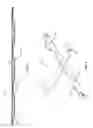
FIG. 1 is a schematic, sectional view of an integrated vehicle skin according to one embodiment of the present technology.
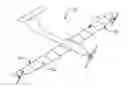
FIG. 2 is a perspective view of a UAV including integrated wing skins, according to one embodiment of the present technology.
DETAILED DESCRIPTION OF THE DRAWINGS
Various embodiments of the invention will now be described. The following description provides specific details for a thorough understanding and enabling description of these embodiments. One skilled in the art will understand, however, that the invention may be practiced without many of these details. Additionally, some well-known structures or functions may not be shown or described in detail so as to avoid unnecessarily obscuring the relevant description of the various embodiments.
The terminology used in the description presented below is intended to be interpreted in its broadest reasonable manner, even though it is being used in conjunction with a detailed description of certain specific embodiments of the invention. Certain terms may even be emphasized below; however, any terminology intended to be interpreted in any restricted manner will be overtly and specifically defined as such in this detailed description section.
Where the context permits, singular or plural terms may also include the plural or singular term, respectively. Moreover, unless the word “or” is expressly limited to mean only a single item exclusive from the other items in a list of two or more items, then the use of “or” in such a list is to be interpreted as including (a) any single item in the list, (b) all of the items in the list, or (c) any combination of items in the list. Further, unless otherwise specified, terms such as “attached” or “connected” are intended to include integral connections, as well as connections between physically separate components.
As shown in FIG. 1, in one embodiment, an integrated skin 10 for a vehicle component, such as for a UAV wing, a boat or submarine hull, a spacecraft wing, and so forth, includes a composite material 12 co-cured with an array of solar cells 14 (“solar array”). The composite material 12 may include a glue-based or epoxy-based resin reinforced with fibers of glass, Kevlar®, or another suitable electrically insulative material that creates electrical isolation from the solar array.
Any suitable solar cells 14 may be used, including cells physically connected by interconnects 15 in an array or string, or individual cells. For ease of description, a solar array will be discussed below. As used herein, the terms “solar array,” “solar-cell array,” or “array of solar cells” encompass any collection of solar cells, whether or not they are physically connected with one another.
The composite material 12 covers the bottom surfaces of the cells 14 of the solar array. In one embodiment, the composite material 12 also extends beyond one or more sides or edges 18 of one or more of the solar cells 14. One or more of the solar cells 14 may be surrounded by the composite material 12 on all sides or on fewer than all sides. As shown in FIG. 1, the upper surface of the composite material 12 extending beyond the edges 18 of the solar cells 14 may be coplanar or substantially coplanar with the upper surfaces of the cells 14 in the solar array. As used herein, the term “substantially coplanar” shall encompass embodiments in which the upper surface of the composite material 12 is coplanar or nearly coplanar with the upper surfaces of the solar cells 14.
A coating 16, such as a spray-on fluorinated polymer coating, covers the upper surface of the solar array and optionally covers the upper-surface portions of the composite material 12 extending beyond the edges 18 of the solar cells 14. The coating 16 protects the solar cells 14, and optionally the composite regions, from the environment or other potentially harmful elements, such as harmful UV radiation, transportation and handling loads, chemicals, sea water, and so forth. The coating 16 is preferably self-adhering such that a separate layer of adhesive is not required to affix the coating 16.
In one embodiment, the coating 16 is optically clear so as not to obstruct the solar cells 14 from absorbing sunlight. The coating 16, for example, may be greater than 30% transmissive, preferably greater than 75% transmissive, of light at wavelengths of 300 nm and above.
In some embodiments, the coating 16 may be applied in a manner other than spraying. In any event, it is preferable that the coating be in the form of a liquid so that it may be meaningfully thinner than the ETFE sheets and plastic sheets used in existing systems. In one embodiment, the coating 16 has a thickness of approximately 0.001 to 0.002 inches, and a weight per area of approximately 0.00003 to 0.0005 pounds per square inch. In other embodiments, thicker or thinner layers of coating 16 may be used. For example, the coating may have a thickness up to 0.005 or 0.010 inches in some cases.
By using a combination of an electrically insulative composite material co-bonded to the solar cells, the coefficient of thermal expansion (CTE) of each of these materials can be relatively similar. And the coating 16, which does not require a separate layer of adhesive to bond it to other system components, is preferably thin enough that it does not appreciably affect the CTE of the completed skin assembly. Existing systems including thick ETFE sheets or thick layers of adhesive, conversely, may experience failure under certain conditions due to the large disparities between CTE values of materials in the system.
For example, Kevlar® has a CTE of approximately −0.5×10⁻⁶/K to −1.5×10⁻⁶/K, fiberglass has a CTE of approximately 5.0×10⁻⁶/K to 7.0×10⁻⁶/K, and solar cells have a CTE of approximately 3.0×10⁻⁶/K to 4.0×10⁻⁶/K. The CTE of ETFE, conversely, is approximately 20×10−6/K to 100×10−6/K, while the CTE of silicone adhesives commonly used in existing systems is approximately 180×10−6/K to 220×10−6/K. When using materials of meaningful thickness and disparate CTE values to encapsulate the solar cells, expansion and contraction that occurs at very high or very low temperatures can cause the solar cells to crack or otherwise break. Thus, the integrated skin 10, in which the CTE values of the co-bonded materials are relatively close to each other, and the coating 16 is very thin, will be more physically stable at extreme temperatures than existing systems.
The integrated skin 10 may be formed in a mold or similar device. In one embodiment, the array of solar cells 14, or other suitable arrangement of solar cells 14, is placed face down in the mold, such that the upper surface of the solar array faces into the mold. Next, the composite material 12 is injected or otherwise introduced into the mold along the back side of the solar array. In one embodiment, a sheet of composite material 12 may be placed onto the back side of the solar array.
The mold may be configured such that the composite material 12 extends beyond one or more sides or edges 18 of one or more of the solar cells 14. In one embodiment, as shown in FIG. 1, for example, the upper surface of the composite material 12 may be substantially coplanar with the upper surfaces of the solar cells 14 on one or more sides of the solar cells 14.
Heat and pressure are applied to the mold to form the integrated skin 10. Once the integrated skin 10 cools, it may be removed from the mold. In one embodiment, a coating 16, such as a fluorinated polymer coating, may then be sprayed onto or otherwise applied to the upper surface of the solar array, and optionally onto the upper surface of the composite material located to the sides of the solar cells 14. The integrated skin 10 may then be applied or attached to a vehicle, such as a UAV wing, a boat or submarine hull, a spacecraft wing, and so forth, by bonding, fusing, mechanical attachment, or any other suitable mechanism.
The integrated skin 10 provides several advantages over existing systems. For example, it can be substantially thinner and lighter than systems employing bonded ETFE sheets or plastic coverings. The liquid polymer coating 16 may, for example, be approximately 14 times lighter and 12 times thinner than plastic coverings and adhesives used to bond the coverings, and approximately 21 times lighter and 16 times thinner than ETFE sheets and adhesives used to bond the sheets. These weight and size benefits can be achieved while maintaining the skin's surface flatness or uniformity at approximately 0.001 inches, which promotes laminar airflow across the skin 10.
The integrated skin 10 may also be unlimited in size and curvature, constrained only by the dimensions of the mold or other device in which it is formed. Existing systems, conversely, are limited by relatively small press sizes, or are limited in curvature due to the manner in which the solar cells are mounted on the skins. Thus, the integrated skin 10 may be configured for use on high-end structures having great size or curvature.
FIG. 2 illustrates a UAV 20 including integrated skins 22, such as those described above, covering its wings 24. The integrated skins 22 may cover the entire surface area of the wings, or they may cover a lesser portion of one or both wings 24. Integrated skins 22 of this nature may also be used on other vehicles and structures, such as boat or submarine hulls, spacecraft wings, and so forth.
Any of the above-described embodiments may be used alone or in combination with one another. Further, the integrated vehicle skin may include additional features not described herein. While multiple embodiments have been described, various changes and substitutions may of course be made, without departing from the spirit and scope of the invention. The invention, therefore, should not be limited, except by the following claims and their equivalents.
Claims
1. An integrated skin for a structure, comprising:
a composite material co-cured with an array of solar cells such that an upper surface of the composite material is substantially coplanar with an upper surface of the solar-cell array between neighboring solar cells; and
a liquid coating covering the upper surface of the solar-cell array, with no intervening layer of ETFE between the solar-cell array and the liquid coating.
2. The integrated skin of claim 1 wherein the coating covers at least a portion of the upper surface of the composite material.
3. The integrated skin of claim 1 wherein the composite material covers a bottom surface of the solar-cell array.
4. The integrated skin of claim 3 wherein the composite material extends around one or more edges of the solar-cell array.
5. The integrated skin of claim 1 wherein the coating comprises a fluorinated polymer coating.
6. The integrated skin of claim 5 wherein the fluorinated polymer coating is optically clear.
7. The integrated skin of claim 1 wherein the composite material comprises a glue-based or epoxy-based resin reinforced with fibers of glass or aramid.
8. The integrated skin of claim 1 wherein the coating has a thickness of approximately 0.001 to 0.005 inches.
9. The integrated skin of claim 1 wherein the coating has a weight per area of approximately 0.00003 to 0.005 pounds per square inch.
10. An integrated skin for a structure, comprising:
a composite material co-cured with an array of solar cells such that the composite material covers a bottom surface of the solar-cell array; and
an optically clear coating covering an upper surface of the solar-cell array, wherein the coating comprises a self-adhering material that is directly adhered to the upper surface of the solar-cell array without the use of a separate adhesive.
11. The integrated skin of claim 10 wherein the composite material extends around one or more edges of the solar-cell array.
12. The integrated skin of claim 10 wherein an upper surface of the composite material is substantially coplanar with the upper surface of the solar-cell array.
13. The integrated skin of claim 12 wherein the coating covers at least a portion of the upper surface of the composite material.
14. The integrated skin of claim 10 wherein the coating comprises a fluorinated polymer coating.
15. The integrated skin of claim 10 wherein the coating is at least 75% transmissive of light at wavelengths of 300 nm and above.
16-20. (canceled)
21. The integrated skin of claim 1 wherein the coating comprises a self-adhering material that is directly adhered to the upper surface of the solar-cell array without the use of a separate adhesive.
22. An integrated skin for a structure, comprising:
a composite material co-cured with an array of solar cells, the composite material comprising a glue-based or epoxy-based resin that is bonded to the solar-cell array without the use of a separate adhesive; and
a liquid coating covering and directly contacting an upper surface of the solar-cell array.
23. The integrated skin of claim 22 wherein the coating comprises a self-adhering material that is directly adhered to the upper surface of the solar-cell array without the use of a separate adhesive.
24. The integrated skin of claim 22 wherein an upper surface of the composite material is substantially coplanar with the upper surface of the solar-cell array between neighboring solar cells.
25. The integrated skin of claim 12 wherein the upper surface of the composite material is substantially coplanar with the upper surface of the solar-cell array between neighboring solar cells.
Images & Drawings included:
Sources:
- United States Patent and Trademark Office - verify current appl. status at the USPTO↗
Recent applications in this class:
- » 20250056901 2025-02-13
CELL MODULE - » 20240429334 2024-12-26
FLEXIBLE CRYSTALLINE SILICON PHOTOVOLTAIC MODULE AND MANUFACTURING METHOD THEREFOR - » 20240379887 2024-11-14
SOLAR CELL AND SOLAR CELL MANUFACTURING METHOD - » 20240363779 2024-10-31
Photovoltaic Panel Packaging Structure and Method for the Same - » 20240347657 2024-10-17
UV-RESISTANT PHOTOVOLTAIC MODULE - » 20240313141 2024-09-19
SEALING MATERIAL SHEET FOR SOLAR-CELL MODULE AND SOLAR-CELL MODULE USING THE SAME - » 20240304741 2024-09-12
CELL MODULE - » 20240222536 2024-07-04
PHOTOVOLTAIC MODULE AND PREPARATION METHOD THEREFOR - » 20240213386 2024-06-27
Encapsulant Sheet with Low Potential Induced Degradation - » 20240178335 2024-05-30
Wrapped Photovoltaic Cell and Photovoltaic Module
Recent applications for this Assignee:
- » 20240116624 2024-04-11
Systems and methods for aerodynamic deployment of wing structures - » 20210253219 2021-08-19
Systems and methods for aerodynamic deployment of wing structures - » 20180335460 2018-11-22
Human sensing using electric fields, and associated systems and methods - » 20180072413 2018-03-15
Rotating wing assemblies for tailsitter aircraft - » 20180022152 2018-01-25
Wheels having multiple-piece composite structures - » 20170283052 2017-10-05
Rotating wing assemblies for tailsitter aircraft - » 20170267022 2017-09-21
Wheels having multiple-piece composite structures - » 20170101017 2017-04-13
Transportable ground station for an unmanned aerial vehicle - » 20160229299 2016-08-11
Transportable ground station for an unmanned aerial vehicle - » 20150102157 2015-04-16
Vertical take-off and landing aircraft