Method and system for creating unloading slots in oil and gas wells by stretch-slotting perforation
US20180340401A1
2018-11-29
15/731,325
2017-05-26
Abstract:
For slot perforating of oil or gas wells according to a stretch-slotting perforation technology with a tubing having a component for exiting a working fluid for perforation of slots, a working fluid is supplied through the tubing so that the working fluid exits outwardly by the component and a pressure of the working fluid is increased so that the tubing elongates exclusively under the action of the pressure of the working fluid and the component displaces longitudinally and perforate the slots in a well by the working fluid.
Interested in similar patents?
Get notified when new applications in this technology area are published.
Classification:
E21B43/114 » CPC main
Methods or apparatus for obtaining oil, gas, water, soluble or meltable materials or a slurry of minerals from wells; Perforators; Permeators Perforators using direct fluid action on the wall to be perforated , e.g. abrasive jets
E21B29/06 » CPC further
Cutting or destroying pipes, packers, plugs, or wire lines, located in boreholes or wells, e.g. cutting of damaged pipes, of windows ; Deforming of pipes in boreholes or wells; Reconditioning of well casings while in the ground Cutting windows, e.g. directional window cutters for whipstock operations
Description
BACKGROUND OF THE INVENTION
The present invention relates to technology of slot perforation in oil and gas wells.
Processes of opening productive formations in oil and gas wells by cutting of continuous slots along the borehole, through the casing and cement sheath into the formation—slot perforation—are well known and widely used.
It is known that opening of a productive formation by cutting of continued slots extending along the borehole provides a much greater effect than cumulative or spot perforations, since a large surface area provides a good and reliable hydrodynamic connection of a productive layer with the well, achieves unloading of stress conditions in the near wellbore zone and accordingly increases the permeability, thus increasing the influx of product (oil, gas or water).
The longitudinal slots (slot perforation) can be created by mechanical, hydraulically, hydro-mechanical, pneumatic or electro-mechanical ways, depending on the operating principle of the cutting device.
When using hydro-slotting perforation method, the maximum cutting depth by using the rectilinear motion of the working fluid jet (water with abrasive additive (sand) at a constant speed along the borehole does not exceed 1.5 meters (or 5 feet), due to the physics of this phenomenon and numerous experiments in practice. Increase in pressure leads to simulation of hydraulic fracturing and an increase in the concentration of an abrasive additive (sand) causes early erosion of nozzles and perforator, but does not affect the depth.
The use of a working solution consisting of water and an abrasive additive during jet perforation provides much greater depth of penetration and is much more effective, as compared with using only of water jet. For example, in mechanical, hydro-mechanical or electro-mechanical constructions with circular saws it is impossible to use abrasive additives (sand), and therefore the depth of the cut can only slightly exceed the diameter of the saw blade.
It has been determined that a point or any jet perforation applied to one point does not provide a sufficient depth of penetration into the formation (in practice less than a foot regardless of application time), because the reverse jet with sludge and sand dampens the direct jet. With the slotting perforation, the jets perform a movement along the borehole, direct jet does not intersect with reverse jet, sludge and sand are captured out by the flow of working fluid on the surface, and a so-called “excavation effect” occurs allowing to penetrate deeper and deeper into the rock.
For creating a continuous slot (slot perforation) through the casing and cement sheath into the formation, the motion of a working fluid jet along the borehole must be straightforward and with constant speed. It is however not possible to create such a movement by moving the tubing or coiled tubing from the surface, because any tubing or coiled tubing has different elongation parameters and own resonant frequency, so the tubing will jump in a planned cutting place and a continuous gap will not form. The movement of the working fluid jet must be occurring directly in a cutting place in the well, and for this reason the process of slotting perforation uses special slot-perforation tools. However, all their designs are different from self-generating movement of the jet along the wellbore, and they have very little depth of penetration and correspondingly very low efficiency.
Experimentally it has been found that when using hydraulic slot perforation method for optimal conditions for creation of continuous deep slots along the borehole, through the casing and cement sheath into the formation, pressure difference over the nozzles with an internal diameter of the outlet 5 mm (0.2 inches) must be ˜3500 psi or 25.3 Mpa.
Experimentally it also has been found that the optimal number of nozzles in the perforator, giving the greatest effect on the opening area and depth is 4 nozzles in one row (4 slots). When using a perforator with two or more rows of nozzles as well as with the use of two or more perforators, one after another, only one bottom row of nozzles or one bottom perforator is working, while the remaining parts do not participate in the process. Inordinate increase of the number of nozzles also does not provide a positive effect and leads to almost complete loss of kinetic energy of the cutting jets, so that only well moisturizing occurs, but not any depth or opening area.
Abrasive quartz sand or other abrasive components can be used as abrasive particles, with a weight of particles equal to the weight of the abrasive quartz sand particles (particles with less weight will have a smaller kinetic energy for cutting), and with dimension not greater than the initial diameter of the inner hole of nozzles (otherwise they will interfere with each other when passing through the nozzle's hole, which will also reduce the flow kinetic energy). The abrasive imparts to working fluid jets a great destructive power, and water (liquid) is required transportation of abrasive particles. Flow velocity at the outlet of the nozzle reaches 1000 m/sec (3280 ft/sec).
Slot perforation perfectly meets the main requirements of Geological and Technical conditions at the opening of productive formations:
-
- Large opening area of a casing, cement ring and productive formation—it provides a good hydro-dynamic connection between a productive layer and a well;
- Depth of penetration into the productive formation—it provides the unloading the stress conditions in the near wellbore zone and accordingly increases the permeability;
- Preventing formation of crusts on the border of opening zone—this prevents the inflow of useful product and requires additional actions;
- Preventing formation of a cracked of cement ring—it provokes the flows of water and increases the risk of well's flooding;
Slot perforation it is ecologically friendly process which does not spoil the environment, as it uses only water and abrasive additives (sand). Slot perforation process also involves the use of special (hydraulic, mechanical or electrical) tools, which provide the linear motion of working fluid jets along the wellbore with a constant velocity, optimal and sufficient for cutting deep slots through the steel casing, cement sheath into the productive formation in the immediate zone of the cutting within the borehole.
Using the special slot-perforation hydraulic tool for hydro-slotting perforation operations requires special skills, knowledge and training in the installation of this equipment, conducting the slotting perforation process, calculation of technological parameters, prevention of backfilling equipment by sand and other emergency situations. Furthermore, a depth of cut is directly dependent on a cutting speed, and therefore the slot-perforation tool strongly dependent on temperature of the working fluid, which may change during a working day.
In view of the above-presented consideration it is believed to be advisable to improve the technology of slot perforation in oil and gas wells.
SUMMARY OF THE INVENTION
Accordingly, it is an object of the present invention to provide a method and a system for slot perforation in oil and gas wells, which are further improvements of the existing methods and system of slot perforation in oil or gas well.
In keeping with these objects and with others which will become apparent hereinafter, one feature of the present invention resides, briefly stated, in a method of slot perforating of oil or gas wells without the use of special and expensive tools, and comprising steps of providing a tubing having means for exiting a working fluid for perforation of slots; supplying the working fluid through the tubing so that the working fluid exits outwardly by said means; and increasing a pressure of the working fluid so that the tubing elongates exclusively under the action of the pressure of the working fluid and said means displace longitudinally and perforate the slots in a well around said means.
When the method is performed according to the present invention, the slot perforation process and the creation of the limited length continuous cutting slots along a wellbore is carried out without the use of special slot-perforation (hydraulic, mechanical or electrical) equipment and without movement of the tubing (straight or coiled tubing) from the surface during the perforation of the slots.
It provides a continuous rectilinear motion of the working fluid jets along the borehole to create continuous slots, without irregular and non-uniform movements of the tubing or coiled tubing from the surface, which cannot create conditions for cutting deep and geometrically correct slots.
The method according to the present invention can be used practically for any service divisions which operate in oil and gas industry, which does not have special equipment for slot-perforation operations. It can be used for activation and intensification of oil, gas, injection and hydro-geological, old and newly drilled, vertical or inclined from the vertical wells. The method is also applicable to any formation (carbonates, sandstones, limestone, shale's, etc.); in thin-interbedded layers; in close-drowning wells; in the loose sands wells; with high-temperature or low-temperature and high-viscosity wells; low-permeability and low-porosity conditions; before, after or together with other methods of opening the productive formation (hydraulic fracturing, for example); together with chemical treatment or without it.
According to a further feature of the present invention, the inventive method includes adjusting a longitudinal size of slots by adjusting a value of pressure of the working fluid without movement of the tubing (straight or coiled tubing) from the surface during the perforation of the slots. The greater the pressure of the working fluid, the greater elongation of the tubing and the greater is the longitudinal dimension of the perforated slots, and vice versa.
According to a further feature of the present invention, after the slots of certain dimension have been perforated by the inventive method, the tubing with said means can be longitudinally displaced, for example longitudinally upwardly, the working fluid is again supplied under pressure through the tubing and exits through said means, and another set of slots is perforated at a different, spaced longitudinal location from the first-mentioned set of slots and without movement of the tubing from the surface during the perforation of the slots.
According to a further feature of the present invention, the method of the invention can be carried out so that the slots of the first mentioned set and the slots of the second-mentioned set longitudinally communicate or do not communicate with each other.
According to a further feature of the present invention a system for slot perforating of oil or gas wells is proposed, including a tubing having means for exiting a working fluid for perforation of slots; means supplying the working fluid through the tubing so that the working fluid exits outwardly by said means; and means increasing a pressure of the working fluid so that the tubing elongates exclusively under the action of the pressure of the working fluid and said means displace longitudinally and perforate the slots in a well around said means.
According to a further feature of the present invention, the inventive system includes means adjusting a longitudinal size of slots by adjusting a value of pressure of the working fluid without movement of the tubing (straight or coiled tubing) from the surface during the perforation of the slots. The greater the pressure of the working fluid, the greater elongation of the tubing and the greater is the longitudinal dimension of the perforated slots, and vice versa.
According to a further feature of the present invention, the system is provided with means operative so that after the slots of certain dimension have been perforated by the inventive method, the tubing with said means can be longitudinally displaced, for example longitudinally upwardly, the working fluid is again supplied under pressure through the tubing and exits through said means, and another set of slots is perforated at a different, spaced longitudinal location from the first-mentioned set of slots and without movement of the tubing from the surface during the perforation of the slots.
According to a further feature of the present invention, the system is provided with means operative so that when the invention is carried out the slots of the first mentioned set and the slots of the second-mentioned set longitudinally communicate or do not communicate with each other.
The method and system according to the present invention thus implement the new stretch-slotting technology for creating unloading slots in oil and gas wells.
The novel features of the present invention are set forth in the appended claims.
The invention itself however both as to its structure and its method operation will best understand from the following description of the preferred embodiments which is accompanied by the following drawings.
BRIEF DESCRIPTION OF THE DRAWINGS
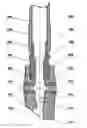
FIG. 1 is a view showing a connection diagram of a tubing or coiled tubing with an adapter and with a perforator with nozzles used in a method for creation of perforating slots in oil and gas well according to the present invention;
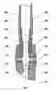
FIG. 2 is a view showing a design of the adapter illustrated in FIG. 1 and used in the method of the present invention;
FIG. 3 is a view showing a design of the perforators illustrated in FIG. 1 and used in the method of the present invention and provided with two, four and three nozzles;
FIG. 4 is a view showing a design of the nozzles used in the method of the present invention; and
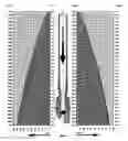
FIG. 5 is a view showing a cutting slot chart with a pressure differential in 3000 psi (20.7 Mpa) on a length and depth of the slot.
DESCRIPTION OF THE PREFERRED EMBODIMENTS
The slot perforation method and system for creation of continuous slots along the borehole using the physical elongation of tubing or coiled tubing when applying the working fluid under the pressure in accordance with the present invention is carried out as follows.
As shown in the drawings, the method and system according to the present invention utilize mainly the following components with following parts identified with following reference numerals:
- 101 The lower end of standard tubing or coiled tubing;
- 102 Coupling sleeve of standard tubing or coiled tubing for connection;
- 103 Cone thread of standard tubing or coiled tubing for connection;
- 104 The upper end of the adapter for connection with standard tubing or coiled tubing;
- 105 Cone thread of the adapter for connection with a standard tubing or coiled tubing;
- 106 A seat of the valve ball for testing of all connections of all sections of tubing in assembly per one time.
- 107 Technological turnkey recess to tighten the adapter when connecting.
- 108 Perforator.
- 109 Cone thread of perforator for connection with adapter.
- 110 Cone thread in the body of perforator for screwing of the nozzles.
- 111 Nozzles with nozzle-holders.
- 112 Stiffening ribs of the perforator for prevent touch and damages of the nozzles to the casing walls during round trip operations.
- 113 Beveled end of perforator. In case of accidental lowering on the ground is not covered with sand.
- 114 Position of the working valve ball during slot perforation process, closes a direct flow of a working fluid to direct it to working nozzles of the perforator.
- 115 Bottom hole of the perforator for the forward and backwash located on the beveled surface of the perforator. In case of accidental lowering on the ground is not covered with sand.
- 116 A seat of the working ball, closes a direct flow of a working fluid to direct it to working nozzles of the perforator.
- 117 Straight abutment end of the perforator. In case of accidental lowering on the ground prevents drowning the perforator in the sand that correspondingly leaves the possibility for forward and backwash.
An adapter FIG. 2 connects the perforator FIG. 3 to a standard tubing or coiled tubing. The adapter is a tail and separate element. A seat 106 is located inside the adapter and constructed for a valve ball for testing whether the tubing sections are hermetic. The ball in the valve closes access of pressure to the perforator. After the testing, the valve ball is washed to the surfaced by backwashing of the well. Then a metal ball is introduced into the tubing and it freely passes through an opening of the seat, is placed in a seat of the perforator, and closes a direct flow of a working fluid to direct it to working nozzles of the perforator.
FIG. 3 shows variants of the perforators with 4 and 3 stiffening ribs of the perforator and with 2, 3 and 4 nozzles.
FIG. 4 shows jet cutting nozzle, consisting of (110) nozzle holder and (111) hard alloys (carbide+tungsten+bonding additives) cone nozzle.
FIG. 5 shows a smooth curve cutting the slots, as described above.
The method of creating unloading slots in oil and gas wells according to the present invention is carried out substantially in the manner which is described below.
- 1. Installation (FIG. 1).
- a) At the end of tubing or coiled tubing the adapter (FIG. 2) and perforator e(FIG. 3) with working nozzles (FIG. 4) are connected as for standard slot perforation operation.
- b) Tubing with perforator are lowered to a required defined depth of the first lower interval planned to cut.
- 2. Correction (Optional).
- a) Logging. For a more accurate determination of the depth the correlation logging can be made (gamma ray logging+casing collar locator logging). The procedure is conducted through the tubing which is already lowered into the borehole (without surfacing).
- b) Correction. Then the correction of perforator position is made. For indication of the position of the perforator in the well between the adapter and tubing, previously a marker is coupled. During installation of the cutting interval it is necessary to consider the stretching column (elongation) at a pressure of the working fluid equal to 3000 psi (20.7 Mpa).
- 3. Cleaning (Optional). Direct flushing of tubing is made to clean from a possible dirt, sand or foreign particles.
- 4. Tubing pressure test (Optional). All connections of tubing (all assembly lines) are tested at once.
- a) Lower test ball in the tubing from the surface.
- b) When the ball reaches the saddle in the adapter (FIG. 2) it is given a pressure up-to 7000 psi (48 Mpa) during 1 (one) minute (or watching the maximum allowable pressure in the table for tubing or coiled tubing depending on model). If pressure does not drop the connection is good.
- c) Cut the pressure. By reverse flushing push out the testing ball is pushed out to the surface.
- 5. Entry in the working mode (˜15 min).
- a) Lower working metal ball into the tubing from the surface.
- b) Wait until the ball reaches the saddle in the perforator (˜5 min). Perhaps hasten the fall of the ball by a little pressure ˜1000 psi-1500 psi (6.9 Mpa-10.3 Mpa).
- c) Start the pressure. Gradually increase the pressure to 3000 psi (20.7 Mpa).
- d) Start the abrasive additives (sand) with the density—concentration of abrasive additives (sand) ˜15 kg/m2-20 kg/m2 (1 lb/ft2-1.25 lb/ft2). Wait until the first batch of sand reaches the nozzles (˜4-6 min).
- e) Give time for working fluid jets under the pressure to make a hole (cut) in the casing, cement sheath and formation (˜3-5 min).
- f) Increase the concentration of abrasive additives (sand) up-to ˜20 kg/m2 (1.25 lb/ft2)-25 kg/m2 (1.6 lb/ft2).
- 6. Slot perforation (˜40 min).
- a) Gradually increase the pressure of the working fluid. The rate of increase the speed should be around ˜80 psi per min (0.5 Mpa per min). The concentration of abrasive additives (sand) maintained at the same rate ˜20 kg/m2 (1.25 lb/ft2)-25 kg/m2 (1.6 lb/ft2).
- In this mode, the tubing will gradually expand as the pressure increases, and the working fluid jets will smoothly move along the borehole with velocity, sufficient for creating (cutting) the optimal for described method, continuous slots through the steel casing, cement sheath into the productive formation in the immediate zone of the cutting within the borehole. Cutting speed in the above mode will be around 5 mm per min (0.2 inches per min).
- b) Increasing the pressure occurs before maximum permissible for used type of tubing or coiled tubing, or before maximum possible for used type of pump, for example 6000-6300 psi (41.4-43.4 Mpa).
- At the speed of increase the pressure in 80 psi per min (0.5 Mpa per min) and correspondingly with the cutting speed around 5 mm per min (0.2 in per min) the interval between the initial (3000 psi (20.7 Mpa) and final pressure (6000-6300 psi (41.4-43.4 Mpa) will be reached in about 40 minutes. At the cutting speed around 5 mm per min (0.2 inches per min) for 40 min tubing will be elongate on ˜20 cm or 200 mm (˜8 inches) and correspondingly the length of the continuous cutting slots will be the same size ˜20 cm or 200 mm (˜8 inches).
- The initial pumping (slurry) rate should be around 4 barrels per min (0.6 m2 per min) for perforator with 2 nozzles and around 5 barrel per min (0.8 m? per min) for perforator with 4 nozzles. Pumping (slurry) rate has a direct dependence on the internal diameter of the nozzles, and respectively by this value can be make the conclusions on erosion nozzles.
- 7. Flushing (˜15 min).
- a) After reaching the maximum pressure stop the flow of abrasive additives (sand). The pressure does not change.
- b) Wait until the last batch of sand reaches working nozzles in the perforator (˜4-6 min), then washed at the same pressure for another 10 minutes (or until the clean water).
- c) Stop the pressure.
- 8. Lifting the tubing or coiled tubing with perforator to the next cutting interval.
- 9. Repetition of the procedure steps 5-8 for all scheduled cutting intervals.
- 10. Completion (˜20 min).
- a) After completing the process of cutting all intervals recommended once again to rinse all the well, for that pull the tubing or coiled tubing with perforator to the bottom of the first cutting interval, applying the pressure ˜5000 psi (34.5 Mpa) and washed during 20 min (or until clean water).
- The final washing will be more efficient and faster if with the reverse flushing rinse, the ball from the perforator to the surface, then make a powerful direct washing of the wells through the large central perforator's hole (not through the nozzles).
- b) Lift the tubing or coiled tubing with perforator on the surface.
The elongation of the tubing can be calculated as disclosed below.
The elongation of tubing or coiled tubing depends on the material, from which they are made (from weight one linear meter or one linear foot and accordingly on the wall thickness of tubing or coiled tubing) and length (depth). Elongation is calculated by derivative from formula of Hook. When calculating the elongation is necessary to consider, that perforator is not a closed space, and working fluid under the pressure flows out through the nozzles. Applied to the slot perforation process and in view all specific components, formula for calculating the elongation of the tubing or coiled tubing is as follows:
EL=(0.06×(AP×(0.5×PL tub+PD noz+PΣL)×LD))/EY×ξ×AS
- EL is an elongation of tubing or coiled tubing under the working fluid pressure (m);
- AP is a passage tubing or coiled tubing area (m2);
- PL tub is a pressure loss in the tubing or coiled tubing (Mpa);
- PD noz is a pressure drop across the nozzles in the perforator, for the optimal cutting with the maximum depth of slots, pressure drop across the nozzles must be ˜25.0 (Mpa);
- PΣL is a sum of all the other pressure loss (Mpa);
- LD is a length (depth) of the tubing or coiled tubing, for example 2000 (m);
- EY is a tensile (elastic) modulus (Young's modulus), for steels equal 210 (Gpa);
- ξ is a coefficient of friction the tubing of casing, for vertical wells equal 1.5, for the deviation from the vertical equal 8.0;
- AS is a sectional area of the tubing or coiled tubing (m2);
AP=0.25×π×d2ID tub
- AP is a passage tubing or coiled tubing area (m2);
- π is a mathematical constant, equal 3.14;
- dID tub is an inner diameter (ID) of the tubing or coiled tubing (m);
PL tub=C%×(Dabr−Dwat)×λwat×λcir
- PL tub is a pressure loss in the tubing or coiled tubing (Mpa);
- C % is a volume fraction of the mixture of water and abrasive component (sand), for example, if the concentration 25 kg/m3, the volume fraction is 2.5%;
- Dabr is a density of abrasive component, for abrasive quartz sand ˜2000 (kg/m), depending on the percentage of quartz;
- Dwat is a density of water, usually ˜1000 (kg/m3), depending on the percentage of abrasive component;
- λwat is a friction coefficient when water moves, equal 0.035;
- λcir is a friction coefficient in the annular space, equal 0.04;
PD noz=PW head−(PL tub+PL perf+PL slot+PL felt+PL surf)
- PD noz is a pressure drop across the nozzles in the perforator, for the optimal cutting with the maximum depth of slots, pressure drop across the nozzles must be ˜25.0 (Mpa);
- PW head is a pressure at the wellhead, generated by pump (pumps), for slot perforations process usually up to ˜43.4 (Mpa);
- PL tub is a pressure loss in the tubing or coiled tubing (Mpa);
- PL perf is a pressure loss in the perforator (usually ˜2.0 Mpa);
- PL slot is a pressure loss in the cavity slot, formed by abrasive fluid jet, usually ˜3.5 (Mpa), depends on the depth of the slot and on the rock;
- PL flit is a pressure loss in the filter or shaker (usually ˜1.5 Mpa);
- PL surf is a pressure loss in the piping at the surface (usually ˜1.0 Mpa);
PL perf=(2.5×g×PD noz)/(nnoz×(φ+q)×fID noz×DS con)
- g is an acceleration of free fall coefficient, equal 9.8 (m/sec);
- PD noz is a pressure drop across the nozzles in the perforator, for the optimal cutting with the maximum depth of slots, pressure drop across the nozzles must be ˜25.0 (Mpa);
- nnoz is a number of nozzles in the perforator (2,3 or 4);
- φ is an upload speed ratio, for example 0.82;
- q is an amplification coefficient of power flow in the conical nozzles because of the negative overpressure inside nozzle channel, usually 4.0-4.5;
- fID noz is an inner diameter (ID) of nozzle section, for example 0.04, 0.045, 0.05 (m);
- DS con is a concentration of the abrasive component (sand), for example 25 (kg/m3);
FIG. 5 illustrates an example whose results have been confirmed by tests:
depth of cut interval (depth of nozzles): 2000 m (6562 ft)
outer diameter of the tubing (OD): 60.0 mm (0.06 m) (2.375 inches)
inner diameter of the tubing (ID): 49.3 mm (0.05 m) (1.939 inches)
concentration of abrasive: 25 kg/m3
initial operating pressure: 3000 psi (20.7 Mpa)
final operating pressure: 6000 psi (38.0 Mpa)
From the calculations, it is obtained that elongation the tubing when pressure 3000 psi (20.7 Mpa) is applied is 10.4 cm (3.94 inches), elongation the tubing when pressure 6000 psi (38.0 Mpa) is applied is 24.8 cm (9.8 inches).
After reaching the operating mode 3000 psi (20.7 Mpa) and supply of abrasive with a concentration of 25 kg/m3 the slot perforation process begins.
FIG. 5 shows a smooth curve cutting the slots. At a pressure of 3000 psi (20.7 Mpa) and supply of abrasive quartz sand with a concentration 20-25 kg/m3 begins cutting the steel casing. With a further gradual increase in pressure of the working fluid with the rate of change of pressure approximately equal 80 psi (0.5 Mpa) per each minute, the slots begin to gradually deepen. Increasing the pressure up to 6000 psi (38.0 Mpa) occurs during near 40 minutes. During this period, the slots reaches a length 20 cm (7.9 inches) and a maximum depth around 90 cm (35.4 inches or 3.0 ft). The graph shows that with increasing pressure the curve of cutting begins to weaken and does not reach the level of 1 meter (39.4 inches or 3.3 ft). This is because with further increase in working fluid pressure, cutting jet at the outlet of the nozzle increasingly deviates from the straight form turning into a conical, and, accordingly, cutting force of jet (kinetic energy) begins to decline.
Because of slot perforation stimulation formed the slots in the form of a rectangular triangle when viewed from the sides with the following parties:
one side of a right triangle: 20 cm or 0.2 m (7.9 inches or 0.7 ft)
second side of a right triangle 90 cm or 0.9 m (35.4 inches or 3.0 ft)
third side of a right triangle: c=√a2−b2=92.2 cm or 0.92 m (36.3 inches or 3.0 ft)
Calculation of the slot area of the, if the slot width is 2.54 cm or 0.025 m (1.0 inches or 0.08 ft):
ASLOT=ALEFT SIDE+ARIGHT SIDE+AUPSIDE+ADOWNSIDE
ASLOT=0.5×(0.2×0.9)+0.5×(0.2×0.9)+(0.025×0.9)+(0.025×0.92)=0.226 m2
Slot volume can be calculated as the volume of the parallelepiped bisection:
VSLOT=(0.025×0.9×0.2)/2=0.0023 m3
Calculation of the weight of the sludge (excavated rock) by volume and density (density of sandstones 2250-2670 kg/m3, density of carbonates 2720-2800 kg/m3):
mSLOT=ρROCK×VSLOT=(2250×0.0023) or (2800×0.0023)=5.2 kg or 6.4 kg
As shown, opening of productive layers by slot perforation is possible to conduct without the use any special slot-perforation equipment (or inefficient movement of the tubing from the surface), using only the effect of stretching (elongation) the column (tubing or coiled tubing) at different applied working fluid pressure, and get enough deep continuous cutting slot through the casing, cement sheath in productive formation.
| time | pressure | continuous | drainage | recovery | sludge | |
| (one cut) | drop | length | area | volume | weight | |
| one | 40 min | 21 | Mpa or | 0.2 | m | 0.23 | m2 | 0.0023 | m3 | 5-6 | kg |
| slot | 3000 | psi | 0.7 | ft | 2.5 | ft2 | 0.08 | ft3 | 11-13 | lb | |
| 7.9 | in | 357 | in2 | 140 | in3 | ||||||
| 2 | 40 min | 21 | Mpa or | 0.2 | m | 0.46 | m2 | 0.0046 | m3 | 10-12 | kg |
| nozzles | 3000 | psi | 0.7 | ft | 5.0 | ft2 | 0.16 | ft3 | 22-26 | lb | |
| 7.9 | in | 714 | in2 | 281 | in3 | ||||||
| 3 | 40 min | 21 | Mpa or | 0.2 | m | 0.69 | m2 | 0.0069 | m3 | 15-18 | kg |
| nozzles | 3000 | psi | 0.7 | ft | 7.5 | ft2 | 0.24 | ft3 | 33-39 | lb | |
| 7.9 | in | 1071 | in2 | 420 | in3 | ||||||
| 4 | 40 min | 21 | Mpa or | 0.2 | m | 0.92 | m2 | 0.0092 | m3 | 20-24 | kg |
| nozzles | 3000 | psi | 0.7 | ft | 10.0 | ft2 | 0.32 | ft3 | 44-52 | lb | |
| 7.9 | in | 1428 | in2 | 560 | in3 | ||||||
The present invention is not limited to the details shown since various changes and modifications are possible without departing from the spirit of the invention.
Claims
What is desired to be protected by Letters Patent is set forth in the appended claims:1. A method of slot perforating of oil or gas wells, comprising steps of providing a tubing having means for exiting a working fluid for perforation of slots; supplying the working fluid through the tubing so that the working fluid exits outwardly by said means; and increasing a pressure of the working fluid so that the tubing elongates exclusively under the action of the pressure of the working fluid and said means displace longitudinally and perforate the slots in a well around said means.
2. The method of claim 1, further comprising adjusting a longitudinal size of slots by adjusting a value of pressure of the working fluid without movement of the tubing from the surface during the perforation of the slots, so that he greater the pressure of the working fluid, the greater elongation of the tubing and the greater is the longitudinal dimension of the perforated slots, and vice versa.
3. The method of claim 1, further comprising, after the slots of certain dimension have been perforated by the inventive method, longitudinally displacing the tubing with said means, again supplying the working fluid under pressure through the tubing and exiting through said means, and perforating another set of slots at a different, spaced longitudinal location from the first-mentioned set of slots and without movement of the tubing from the surface during the perforation of the slots.
4. The method of claim 3, further comprising carrying out the method so that the slots of the first mentioned set and the slots of the second-mentioned set longitudinally communicate or do not communicate with each other.
5. A system for slot perforating of oil or gas wells, a tubing having means for exiting a working fluid for perforation of slots; means supplying the working fluid through the tubing so that the working fluid exits outwardly by said means; and means for increasing a pressure of the working fluid so that the tubing elongates exclusively under the action of the pressure of the working fluid and said means displace longitudinally and perforate the slots in a well around said means.
6. The system of claim 5, further comprising means for adjusting a longitudinal size of slots by adjusting a value of pressure of the working fluid without movement of the tubing from the surface during the perforation of the slots, so that the greater the pressure of the working fluid, the greater elongation of the tubing and the greater is the longitudinal dimension of the perforated slots, and vice versa.
7. The system of claim 5, further comprising means, after the slots of certain dimension have been perforated, longitudinally displacing the tubing with said means, supplying the working fluid is again under pressure through the tubing and exiting through said means, and perforating another set of slots at a different, spaced longitudinal location from the first-mentioned set of slots and without movement of the tubing from the surface during the perforation of the slots.
8. The system of claim 7, further comprising means operative so that the slots of the first mentioned set and the slots of the second-mentioned set longitudinally communicate or do not communicate with each other.
Images & Drawings included:


Sources:
- United States Patent and Trademark Office - verify current appl. status at the USPTO↗
Recent applications in this class:
- » 20230127815 2023-04-27
MULTI-ZONE PERFORATE AND TREAT SYSTEM AND METHOD - » 20210254439 2021-08-19
Stimulation treatment using accurate collision timing of pressure pulses or waves - » 20210189844 2021-06-24
Device for jet packing and fracturing and tubular column comprising same - » 20210108491 2021-04-15
Integrated construction method of fracturing and tertiary oil recovery for low-permeability reservoir - » 20210017839 2021-01-21
Multi-zone perforate and treat system and method - » 20200115997 2020-04-16
Apparatus and method for abrasive perforating and clean-out - » 20190106968 2019-04-11
Methods and systems for utilizing an inner diameter of a tool for jet cutting, hydraulically setting packer and shutting off circulation tool simultaneously - » 20180252078 2018-09-06
Abrasive perforator with fluid bypass - » 20180094510 2018-04-05
Methods and systems for utilizing an inner diameter of a tool for jet cutting, hydraulically setting packers and shutting off circulation tool simultaneously - » 20180038207 2018-02-08
Jet perforating and cutting method