CONTAINER HAVING A PETALOID BASE WITH RIB FEET
US20180362205A1
2018-12-20
16/061,148
2016-12-14
Abstract:
Disclosed is a plastics container obtained by blow moulding or stretch blow moulding from a blank, this container including a body, a neck which extends at an upper end of the body and a petaloid base which extends at a lower end of the body, this petaloid base being provided with protruding feet that are separated by recessed valleys that extend radially from a central region of the base, each foot having an external wall which extends in continuation of the body and two side walls that each border a valley and are each connected to the external wall by a fillet, each foot being provided with at least one rib, a lateral portion of which overlaps the fillet.
Interested in similar patents?
Get notified when new applications in this technology area are published.
Classification:
B65D1/0284 » CPC main
Containers having bodies formed in one piece, e.g. by casting metallic material, by moulding plastics, by blowing vitreous material, by throwing ceramic material, by moulding pulped fibrous material, by deep-drawing operations performed on sheet material; Bottles or similar containers with necks or like restricted apertures, designed for pouring contents characterised by shape; Bottom construction having a discontinuous contact surface, e.g. discrete feet
B65D1/44 » CPC further
Containers having bodies formed in one piece, e.g. by casting metallic material, by moulding plastics, by blowing vitreous material, by throwing ceramic material, by moulding pulped fibrous material, by deep-drawing operations performed on sheet material; Details of walls; Reinforcing or strengthening parts or members Corrugations
B65D1/02 IPC
Containers having bodies formed in one piece, e.g. by casting metallic material, by moulding plastics, by blowing vitreous material, by throwing ceramic material, by moulding pulped fibrous material, by deep-drawing operations performed on sheet material Bottles or similar containers with necks or like restricted apertures, designed for pouring contents
Description
The invention relates to the production of containers, particularly bottles, by blow molding or stretch blow molding from blanks (preforms or unfinished intermediate containers) from a thermoplastic material such as PET (polyethylene terephthalate).
A container generally comprises a body, which imparts to the container its volume, an open neck, which extends protruding from an upper end of the body and through which the container is filled (generally by means of a liquid or a paste), and a bottom, which closes the body opposite the neck and forms a base by which the container must be able to rest in a stable manner on a plane surface such as a table.
Generally, it is sought to impart to the bottom a good mechanical rigidity because, besides the fact that the bottom must form a stable seat for the container (not only during transporting operations following its filling but also during its storage and its everyday use by consumers), it must also withstand the hydrostatic pressure exerted by the contents, with possible thermal stresses caused by an elevated temperature of the contents when the contents are introduced hot into the container, or else with a possible pressure from gas dissolved in the liquid (classic case of carbonated beverages).
If it were possible for the container to stay upright, the ideal shape of the bottom would be a sphere, because it would distribute uniformly the stresses that are applied to it. There was a time when containers made of PET were produced with a spherical bottom on which an added cup-shaped base was fitted, made from a more flexible material (particularly from polypropylene, to make possible its snap-fitting onto the bottom). However, this design made recycling difficult, the two materials having to take different tracks, forcing operators responsible for the selective sorting to separate the base from the container themselves.
The development of the petaloid bottom made it possible to get around these problems: such a bottom comprises alternating protruding feet intended to ensure the vertical stand-up of the container placed on a horizontal plane surface, and convex valleys (generally in the shape of sphere portions) that absorb a portion of the forces (thermal, mechanical) exerted by the contents.
It is in containers having petaloid bottoms that carbonated beverages are ordinarily contained. The capacities of these containers can vary: for example, 0.2 L, 0.5 L, 1 L, 1.5 L, 2 L, or more.
Environmental standards (ever more restrictive) and the unpredictable nature of the price of raw materials are forcing manufacturers to reduce the amount of material used, which results in a decrease in weight (and therefore in thickness) of the containers.
On the lightweight petaloid bottoms, unwanted deformations are observed. In particular, on the feet, the appearance of wrinkles is noted. Apart from their unsightly nature, the wrinkles can form incipient breaks, especially when the containers are palletized: added to the stresses due to the internal pressure are actually stresses of compression due to the weight of the superposed containers.
Even the recent improvements made to the petaloid bottoms (see in particular the European patent application EP 2 560 887 in the name of the applicant) do not make it possible to get around these wrinkles.
An object is consequently to propose a petaloid bottom that, although lightweight, is, however, less subject to the uncontrolled deformations than the known petaloid bottoms.
For this purpose, a container made of plastic material obtained by blow molding or stretch blow molding from a blank is proposed, this container comprising a body, a neck that extends at an upper end of the body, and a petaloid bottom that extends at a lower end of the body, this petaloid bottom being provided with protruding feet, separated by hollow valleys that extend radially from a central area of the bottom, each foot having an outer wall that extends in continuation of the body and two sides each bordering a valley and that each adjoin the outer wall by a fillet, each foot being provided with at least one rib, a lateral portion of which straddles said fillet.
By deploying under pressure the contents of the container, this (or these) rib(s) absorb(s) a portion of the deformations induced within the foot that are thus channeled, which prevents the formation of unwanted wrinkles.
Various additional characteristics can be provided, alone or in combination:
-
- at least one rib has an inner end portion that extends at least partway over one side, in continuation of the lateral portion;
- at least one rib has an outer portion that extends at least partway over the outer wall of the foot, in continuation of the lateral portion;
- the rib stops, toward the exterior, on the outer wall of the foot;
- the container comprises at least one rib having two lateral portions that adjoin by the outer portion;
- the outer portion is arched;
- the (or each) lateral portion is arched in the direction opposite to the outer portion;
- the rib follows the contour of an intersection of the foot with a cylinder of revolution around a radial axis;
- the lateral portion is straight;
- the rib follows the contour of an intersection of the foot with a plane;
- the feet having ends that, for the container, define a placement plane, the above-mentioned intersection plane is parallel (or, as a variant, inclined in relation) to the placement plane;
- the container comprises at least two superposed ribs;
- the container comprises three superposed ribs;
- the ribs are equidistant;
- examined ascending in the direction of the neck from an end of the foot, the ribs are of increasing lengths;
- the ribs follow the contour of an intersection of the foot with coaxial cylinders of revolution, with a radial axis and with different radii;
- at least one rib stops, toward the interior, on the adjoining fillet between the outer wall and the side;
- the (or each) rib has a width of between 0.4 mm and 1.5 mm.
Other objects and advantages of the invention will be brought out in the description of an embodiment, given below with reference to the accompanying drawings in which:
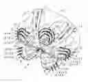
FIG. 1 is a view in perspective, from below, of a container having a petaloid bottom whose feet are ribbed;
FIG. 2 is a detail view, on an enlarged scale, of the bottom of the container of FIG. 1;
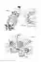
FIG. 3 is a detail view from below, on an enlarged scale, of a ribbed foot;
FIG. 4 is a side view of the bottom of the container;
FIG. 5 is a detail view, on an enlarged scale, of a foot of the container of FIG. 4, according to box V;
FIG. 6 is a detail cutaway view of the bottom, on an enlarged scale, along the cutting plane VI-VI of FIG. 5;
FIG. 7 is a view similar to FIG. 4, illustrating a variant embodiment;
FIG. 8 is a detail view, from the side, of a foot of the bottom of FIG. 7;
FIG. 9 is a detail view from below, on an enlarged scale, of a ribbed foot of the bottom illustrated in FIG. 7.
In FIG. 1, a container 1 is shown that is obtained by blow molding or stretch blow molding from a blank (a term designating a raw injection preform or an intermediate container intended to undergo one or more finishing operations) made of plastic material, for example of PET (polyethylene terephthalate).
The container 1 comprises a body 2, which extends along an axis X that can constitute an axis of revolution of the body 2, a neck 3 that extends at an upper end of the body 2, and a petaloid bottom 4 that extends at a lower end of the body 2, opposite the neck 3.
The bottom 4 is provided with protruding feet 5, separated two by two by hollow valleys 6 that extend radially from a central area 7 of the bottom 4.
Each foot 5 extends in axial projection up to an end 8. The ends 8 of the feet 5 are coplanar and together define a placement plane 9 by which the container 1 can rest in a stable manner on a horizontal plane surface (typically a table).
Each foot 5 has an outer wall 10, which extends in continuation of the body 2, and two sides 11 each bordering a valley 6 and which each adjoin the outer wall 10 by a fillet 12.
According to an embodiment illustrated in the figures, and particularly in FIGS. 3 and 4, each fillet 12 will continue to grow from an upper end 13 of the valley 6 in the direction of the end 8 of the foot. In the same direction, the radius of the fillet 12 can be constant, or keep increasing.
As is also seen in FIGS. 3 and 4, each side 11 has a crescent shape (but this shape is not limiting). It will be noted that the boundaries between the different areas of the foot 5 are not sharp edges but are soft (otherwise, these boundaries would accumulate the stresses and would form, under load, an equal number of incipient breaks). For reasons of clarity, however, these boundaries have been visualized in the drawings (in the form of double dot-dash lines).
Each foot 5 has a plane symmetry relative to a radial plane R (containing the axis X of the container 1) passing through its end 8. Each foot 5 thus comprises a single outer wall 10, symmetrical relative to this plane R, two fillets 12 that are the mirror image of one another relative to this plane R, and two sides 11 that are also the mirror image of one another relative to this plane R.
As is seen in the figures, each foot 5 is provided with at least one rib 14. Seen in cross-section, this rib 14 protrudes (i.e., it forms a relief) toward the interior of the container 1 (FIG. 6). As a variant, this rib 14 protrudes toward the exterior of the container.
Regardless of its form (several of them are described below), the rib 14 comprises a lateral portion 15 that straddles the fillet 12, i.e., this lateral portion 15 extends over at least one part of the width of the fillet 12.
The number of ribs 14 present on each foot 5 can be a function of the volumetric capacity of the container 1. Thus, in a large-capacity (1.5 L, 2 L or even 3 L) container 1, each foot 5 can be provided with three ribs 14 (or three pairs of ribs 14 that are symmetrical relative to the radial plane of symmetry R of the foot) that are superposed (see the first bottom 4 illustrated in FIGS. 1 to 5, which comprises, for each foot 5, an upper rib 14.1, an intermediate rib 14.2, and a lower rib 14.3). In a medium-capacity (0.5 L or 1 L) container 1, each foot 5 can be provided with two (or two pairs of) superposed ribs 14 (see the second bottom 4 illustrated in FIGS. 7, 8 and 9, which comprises, for each foot 5, a pair of symmetrical upper ribs 14.4 and a pair of symmetrical lower ribs 14.5). In a low-capacity (less than 0.5 L, for example 0.2 L) container 1, each foot 5 can be provided with a single rib 14 (or with a single pair of ribs 14 that are symmetrical relative to the plane R of symmetry of the foot 5).
At least one of the ribs 14 can have one or more of the following characteristics:
-
- the lateral portion 15 extends over the entire width of the fillet 12, thus joining the outer wall 10 to one of the sides 11 of the foot 5; this is the case with the upper rib 14.1 of the first bottom 4 (FIGS. 3 and 4) and with the ribs 14.4, 14.5 of the second bottom 4 (FIGS. 7, 8, 9);
- the rib 14 extends over the side 11, beyond the fillet 12; the rib 14 then has an inner end portion 16, which extends at least partway over the side 11, in continuation of the lateral portion 15; this is the case with the upper rib 14.1 of the first bottom 4 (FIGS. 3 and 4) and with the two ribs 14.4, 14.5 of the second bottom 4 (FIGS. 7, 8, 9);
- the lateral portion 15 extends over one part only of the fillet 12, extending from the outer wall 10 and stopping in the vicinity of the boundary between the fillet 12 and the side 11: this is the case with the intermediate rib 14.2 of the first bottom 4 (FIGS. 3 and 4);
- the lateral portion 15 extends over one part only of the fillet 12, starting from the outer wall 10 and stopping approximately halfway between the outer wall 10 and the side 11: this is the case with the lower rib 14.3 of the first bottom 4 (FIGS. 3 and 4);
- the rib 14 has an outer portion 17 that extends at least partway over the outer wall 10 of the foot 5, in continuation of the lateral portion 15: this is the case with the upper rib 14.1 of the first bottom 4 (FIGS. 3 and 4) and with the two ribs 14.4, 14.5 of the second bottom 4 (FIGS. 7, 8, 9);
- the rib 14 stops, toward the exterior, on the outer wall 10 of the foot 5: the rib 14 then has an outer end portion 18, which extends partway over the outer wall 10: this is the case with the ribs 14.4, 14.5 of the second bottom 4 of FIGS. 7, 8, 9; the foot 5 illustrated in these figures comprises two superposed pairs of ribs 14 that are symmetrical relative to the plane R of symmetry of the foot 5. The ribs 14.4, 14.5 of each pair are separated from one another, their outer end portions 18 stopping at a distance from one another of several millimeters;
- the outer portion 17 extends over the entire width of the outer wall 10: the rib 14 then comprises two lateral portions 15 that adjoin by the outer portion 17: this is the case with the ribs 14.1, 14.2, 14.3 of the first bottom 4 of FIGS. 3 and 4;
- the outer portion 17 is arched: this is the case with the ribs 14.1, 14.2, 14.3 of the first bottom 4 of FIGS. 3 and 4, the outer portions 17 of which extend along an arch with its concavity turned toward the placement plane 9;
- the (or each) lateral portion 15 is further arched in the opposite direction of the outer portion 17: this is the case with the ribs 14.1, 14.2, 14.3 of the first bottom of FIGS. 3 and 4, whose lateral portions 15 extend along an arch with its concavity turned toward the neck 3;
- the rib 14 follows the contour of an intersection of the foot 5 with a cylinder C of revolution around a radial axis: this is the case with the ribs of the first bottom 4 of FIGS. 3, 4 and 5; in this first bottom 4, and as is clearly visible in FIG. 5, the ribs 14.1, 14.2, 14.3 follow the contour of an intersection of the foot 5 with the respective cylinders C1, C2, C3 of revolution, with the same radial axis A and with different radii;
- in a variant, the rib 14 follows the contour of an intersection of the foot 5 with a plane P that is inclined relative to the placement plane 9: this is the case with the ribs 14.4, 14.5 of the second bottom 4 of FIGS. 7, 8, 9; in a variant, the plane P could be parallel to the placement plane; in both cases, the (or each) lateral portion 15 appears straight instead of being arched;
- the rib 14 has a width L of between 0.4 mm and 1.5 mm.
It is conceivable to combine certain of the above-mentioned characteristics. At least one (or each) rib 14 could thus have an arched outer portion 17 and one (or each) straight lateral portion 15.
Taking into account the rather intricate relief of the foot 5, the general shape of each rib 14 depends on the angle along which the bottom 4 is observed.
Thus, when the first bottom 4 of FIGS. 1 to 5 is observed from below (FIG. 3), each rib 14.1, 14.2, 14.3 has an open U shape. When a foot 5 of this same bottom 4 is observed radially from the outside (see the foot 5 located in the center of FIG. 4), each rib 14.1, 14.2, 14.3 has a circular shape. When a foot 5 of this first bottom 4 is observed from the side (see the feet 5 located on the sides of FIG. 4), each rib 14.1, 14.2, 14.3 has a Gaussian shape.
When a foot 5 of the second bottom 4 of FIGS. 7 to 9 is observed from below (FIG. 9), each rib 14.4, 14.5 also has an open U shape. When a foot of this same bottom is observed from the side (FIG. 8), each rib 14.4, 14.5 extends along a straight line.
When each foot 5 comprises several superposed ribs 14, the ribs 14 can, when examined ascending in the direction of the neck from the end 8 of the foot 5, be of different lengths (for example, increasing, see the first bottom 4 illustrated in FIGS. 2, 3 and 4) or of the same length (see the second bottom 4 illustrated in FIGS. 7, 8 and 9).
When each foot 5 comprises a number of ribs 14 that is greater than or equal to three, they can be equidistant, as in the first bottom 4 illustrated in FIGS. 1 to 5.
The container 1 is designed to be filled with contents under pressure, typically a carbonated beverage, which produces in the container 1 a pressure that can reach 6 bars.
Its petaloid shape makes it possible for the bottom 4 to maintain its shape overall without collapsing, the valleys 6 ensuring, as a result of their spherical shape, a relatively homogeneous distribution of the stresses that they undergo because of the pressure of the contents. The feet 5, for their part, are subject to significant variations of stresses because of their intricate shape. It has been found that the stresses accumulate in the fillets 12, between the outer wall 10 and the sides 11. Each rib 14 contributes, by being deployed toward the exterior of the container 1 (as illustrated in dashed lines in FIG. 6), to channeling the deformations caused by these stresses. In other words, the deformations are localized on the rib(s) 14. Consequently, the uncontrolled (unwanted) deformations of the feet 5 are minimized, indeed eliminated, even when the container 1 is lightweight. The appearance of the container 1 is preserved, as well as its behavior under increased load (particularly when palletizing), with an equal or lower weight.
Claims
1. Container (1) made of plastic material obtained by blow molding or stretch blow molding from a blank, this container (1) comprising a body (2), a neck (3) that extends at an upper end of the body (2) and a petaloid bottom (4) that extends at a lower end of the body (2), this petaloid bottom (4) being equipped with protruding feet (5), separated by hollow valleys (6) that extend radially from a central area (7) of the bottom (4), each foot (5) having an outer wall (10) that extends in continuation of the body (2) and two sides (11) each bordering a valley (6) and that each adjoin the outer wall (10) by a fillet (12), wherein each foot (5) is provided with at least one rib (14), a lateral portion (15) of which straddles said fillet (12).
2. Container (1) according to claim 1, wherein at least one rib (14) has an inner end portion (16) that extends at least partway over one side (11), in continuation of the lateral portion (15).
3. Container (1) according to claim 1, wherein at least one rib (14) has an outer portion (17) that extends at least partway over the outer wall (10) of the foot (5), in continuation of the lateral portion (15).
4. Container (1) according to claim 3, wherein the rib (14) stops, toward the exterior, on the outer wall (10) of the foot (5).
5. Container (1) according to claim 3, further comprising at least one rib (14) having two lateral portions (15) that adjoin by the outer portion (17).
6. Container (1) according to claim 3, wherein the outer portion (17) is arched.
7. Container (1) according to claim 6, wherein the (or each) lateral portion (15) is arched in the direction opposite the outer portion (17).
8. Container (1) according to claim 1, wherein the rib (14) follows the contour of an intersection of the foot (5) with a cylinder (C) of revolution around a radial axis (A).
9. Container (1) according to claim 1, wherein the lateral portion (15) is straight.
10. Container (1) according to claim 1, wherein the rib (14) follows the contour of an intersection of the foot (5) with a plane (P).
11. Container (1) according to claim 10, wherein, the feet (5) having ends (8) that define for the container (1) a placement plane (9), the intersection plane (P) is inclined in relation to the placement plane (9).
12. Container (1) according to claim 10, wherein, the feet (5) having ends (8) that define for the container (1) a placement plane (9), the intersection plane (P) is parallel in relation to the placement plane (9).
13. Container (1) according to claim 1, further comprising at least two superposed ribs (14).
14. Container (1) according to claim 13, further comprising three superposed ribs (14).
15. Container (1) according to claim 14, wherein the ribs (14) are equidistant.
16. Container (1) according to claim 13, wherein, examined ascending in the direction of the neck (3) from an end (8) of the foot (5), the ribs (14) are of increasing lengths.
17. Container (1) according to claim 13, wherein the ribs (14) follow the contour of an intersection of the foot with coaxial cylinders (C1, C2, C3) of revolution, with a radial axis (A) and with different radii.
18. Container (1) according to claim 1, wherein at least one rib (14) stops, toward the interior, on the adjoining fillet (12) between the outer wall (10) and the side (11).
19. Container (1) according to claim 1, wherein the (or each) rib (14) has a width (L) of between 0.4 mm and 1.5 mm.
20. Container (1) according to claim 2, wherein at least one rib (14) has an outer portion (17) that extends at least partway over the outer wall (10) of the foot (5), in continuation of the lateral portion (15).
Images & Drawings included:


Sources:
- United States Patent and Trademark Office - verify current appl. status at the USPTO↗
Recent applications in this class:
- » 20250074648 2025-03-06
LIQUID CONTAINER FOR MASS STORAGE, TRANSPORT, AND DISPLAY - » 20240367845 2024-11-07
Plastic container with flattened supporting feet and blow molding device - » 20240317447 2024-09-26
PLASTIC CONTAINER HAVING A MOVABLE BASE - » 20240270435 2024-08-15
SWIRL BELL BOTTLE WITH WAVY RIBS - » 20240262560 2024-08-08
CONTAINER BASE WITH STRAPS AND DIAPHRAGM - » 20240190605 2024-06-13
BOTTLE WITH AN ENHANCED BOTTOM - » 20240109682 2024-04-04
PLASTIC CONTAINER HAVING A MOVABLE BASE - » 20240059449 2024-02-22
BOTTLE WITH A LIGHT WEIGHTED BASE - » 20230242300 2023-08-03
LIQUID CONTAINER FOR MASS STORAGE, TRANSPORT, AND DISPLAY - » 20230219709 2023-07-13
Swirl bell bottle with wavy ribs