Rigid package for moisture-sensitive adhesive
US20180362227A1
2018-12-20
16/011,807
2018-06-19
✅ Patent granted
US 10,604,311 B2
2020-03-31
-
-
Vishal Pancholi
Wood Herron & Evans LLP
2038-06-19
Abstract:
A container for use in a gravity-fed dispenser, particularly for construction adhesives, includes a top surface with an outlet port, a bottom surface with a venting port and side walls, said side walls including two opposed indentations that provide handle grasps for a user, allowing the user to hold the container in an upside down position while it is attached to a dispenser. The vent on the bottom surface allows the contents to flow evenly through gravity out of the outlet port.
Inventors:
- Michael J. Scanish 7 🇺🇸 Camp Hill, PA, United States
- Earl Buzzard 1 🇺🇸 Albuquerque, NM, United States
- Chris Mahon 1 🇺🇸 Huntington Woods, MI, United States
Assignee:
- Carlisle Intangible, LLC 5 🇺🇸 Scottsdale, AZ, United States
Applicant:
Interested in similar patents?
Get notified when new applications in this technology area are published.
Classification:
B65D51/1627 » CPC main
Closures not otherwise provided for with means for venting air or gas whereby the interior of the container is maintained in permanent gaseous communication with the exterior by means of a passage for the escape of gas between the closure and the lip of the container mouth the closure being for a box-like container
B65D5/4295 » CPC further
Rigid or semi-rigid containers of polygonal cross-section, e.g. boxes, cartons or trays, formed by folding or erecting one or more blanks made of paper; Details of containers or of foldable or erectable container blanks Ventilating arrangements, e.g. openings, space elements
B65D21/0202 » CPC further
Nestable, stackable or joinable containers; Containers of variable capacity; Containers specially shaped, or provided with fittings or attachments, to facilitate nesting, stacking, or joining together stackable or joined together side-by-side and loosely interengaged by integral complementary shapes
B65D1/18 » CPC further
Containers having bodies formed in one piece, e.g. by casting metallic material, by moulding plastics, by blowing vitreous material, by throwing ceramic material, by moulding pulped fibrous material, by deep-drawing operations performed on sheet material; Cans, casks, barrels, or drums characterised by shape of polygonal cross-section
B65D1/20 » CPC further
Containers having bodies formed in one piece, e.g. by casting metallic material, by moulding plastics, by blowing vitreous material, by throwing ceramic material, by moulding pulped fibrous material, by deep-drawing operations performed on sheet material; Cans, casks, barrels, or drums characterised by location or arrangement of filling or discharge apertures
B65D21/023 » CPC further
Nestable, stackable or joinable containers; Containers of variable capacity; Containers specially shaped, or provided with fittings or attachments, to facilitate nesting, stacking, or joining together stackable or joined together one-upon-the-other in the upright or upside-down position Closed containers provided with local cooperating elements in the top and bottom surfaces, e.g. projection and recess
B65D21/0212 » CPC further
Nestable, stackable or joinable containers; Containers of variable capacity; Containers specially shaped, or provided with fittings or attachments, to facilitate nesting, stacking, or joining together stackable or joined together one-upon-the-other in the upright or upside-down position Containers presenting local stacking elements protruding from the upper or lower edge of a side wall, e.g. handles, lugs, ribs, grooves
B65D21/0215 » CPC further
Nestable, stackable or joinable containers; Containers of variable capacity; Containers specially shaped, or provided with fittings or attachments, to facilitate nesting, stacking, or joining together stackable or joined together one-upon-the-other in the upright or upside-down position Containers with stacking feet or corner elements
B65D21/0231 » CPC further
Nestable, stackable or joinable containers; Containers of variable capacity; Containers specially shaped, or provided with fittings or attachments, to facilitate nesting, stacking, or joining together stackable or joined together one-upon-the-other in the upright or upside-down position; Closed containers provided with local cooperating elements in the top and bottom surfaces, e.g. projection and recess Bottles, canisters or jars whereby the neck or handle project into a cooperating cavity in the bottom
B65D25/00 » CPC further
Details of other kinds or types of rigid or semi-rigid containers
B65D25/2894 » CPC further
Details of other kinds or types of rigid or semi-rigid containers; Handles; Integral handles provided on the top or upper wall
B65D25/2897 » CPC further
Details of other kinds or types of rigid or semi-rigid containers; Handles; Integral handles formed in the wall(s), e.g. roughenings, cavities or projections
B65D77/067 » CPC further
Packages formed by enclosing articles or materials in preformed containers, e.g. boxes, cartons, sacks or bags; Articles or materials enclosed in two or more containers disposed one within another; Liquids or semi-liquids or other materials or articles enclosed in flexible containers disposed within rigid containers; Flexible containers disposed within polygonal containers formed by folding a carton blank; Spouts, pouring necks or discharging tubes fixed to or integral with the flexible container combined with a valve, a tap or a piercer
B65D81/263 » CPC further
Containers, packaging elements, or packages, for contents presenting particular transport or storage problems, or adapted to be used for non-packaging purposes after removal of contents; Adaptations for preventing deterioration or decay of contents; Applications to the container or packaging material of food preservatives, fungicides, pesticides or animal repellants with provision for draining away, or absorbing, fluids, e.g. exuded by contents ; Applications of corrosion inhibitors or desiccators for ventilating the contents
B05B9/007 » CPC further
Spraying apparatus for discharge of liquids or other fluent material, without essentially mixing with gas or vapour At least a part of the apparatus, e.g. a container, being provided with means, e.g. wheels, for allowing its displacement relative to the ground
E04D15/00 » CPC further
Apparatus or tools for roof working
E04D15/07 » CPC further
Apparatus or tools for roof working for handling roofing or sealing material in bulk form
B65D51/16 IPC
Closures not otherwise provided for with means for venting air or gas
B65D5/42 IPC
Rigid or semi-rigid containers of polygonal cross-section, e.g. boxes, cartons or trays, formed by folding or erecting one or more blanks made of paper Details of containers or of foldable or erectable container blanks
B65D81/26 IPC
Containers, packaging elements, or packages, for contents presenting particular transport or storage problems, or adapted to be used for non-packaging purposes after removal of contents; Adaptations for preventing deterioration or decay of contents; Applications to the container or packaging material of food preservatives, fungicides, pesticides or animal repellants with provision for draining away, or absorbing, fluids, e.g. exuded by contents ; Applications of corrosion inhibitors or desiccators
B65D21/02 IPC
Nestable, stackable or joinable containers; Containers of variable capacity Containers specially shaped, or provided with fittings or attachments, to facilitate nesting, stacking, or joining together
B65D77/06 IPC
Packages formed by enclosing articles or materials in preformed containers, e.g. boxes, cartons, sacks or bags; Articles or materials enclosed in two or more containers disposed one within another Liquids or semi-liquids or other materials or articles enclosed in flexible containers disposed within rigid containers
B65D25/28 IPC
Details of other kinds or types of rigid or semi-rigid containers Handles
B05B9/00 IPC
Spraying apparatus for discharge of liquids or other fluent material, without essentially mixing with gas or vapour
Description
CROSS-REFERENCE TO RELATED APPLICATION
This application claims the benefit of and priority to prior filed pending Provisional Application Ser. No. 62/521,566, filed Jun. 19, 2017, which is expressly incorporated herein by reference.
BACKGROUND OF THE INVENTION
In many applications, particularly in the construction industry, adhesives are applied from bulk containers using dispensers. In particular, moisture-sensitive two-part adhesive systems can be applied using such dispensers. These dispensers mix the two components and apply the blended adhesive as desired. These two-part adhesive systems can be polyurethanes which are very moisture sensitive. An adhesive dispenser used for such applications is disclosed in U.S. Pat. No. 8,167,170, the disclosure of which is incorporated herein by reference.
Typically, these bulk containers of adhesives are plastic bags or bladders having an outlet port which attaches to the dispenser. The bags are stored in corrugated boxes. These containers are not optimal for a number of reasons. The flexible films may not provide an adequate moisture vapor barrier, particularly when the adhesive is stored for longer periods of time. Also, the packaging itself can be left outside and subjected to rain, temperature extremes and sunlight, including ultraviolet radiation. This reduces useful life of these containers and in turn, can result in the adhesive becoming unsuitable for use.
SUMMARY OF THE INVENTION
The present invention is premised on the realization that a container suitable for moisture-sensitive adhesives or other moisture-sensitive materials can be formed from a rigid thermoplastic plastic which has excellent moisture barrier characteristics. The container includes a top wall, bottom wall and side walls connecting the top and bottom walls and a dispensing port through the top wall. A venting port, in turn, extends through the bottom wall. Opposed indentations in the side walls allow an individual to hold the container with the top wall facing downward for insertion into a gravity-fed dispensing apparatus. The side walls can further include an indentation which receives an adapter designed to connect the outlet port to the inlet of the gravity feed dispenser. This allows the containers of the present invention to be stacked, one on top of the other. This reduces storage requirements. The vent allows for the constant downward flow of the adhesive into the dispenser and, at the same time, the vent can be resealed to allow the partially-used materials be stored.
The objects and advantages of the present invention will be further appreciated in light of the following detailed descriptions and figures in which:
BRIEF DESCRIPTION OF THE DRAWINGS
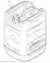
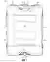
FIG. 1 is a front perspective view of the present invention with the container in the upright position;
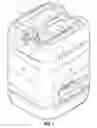
FIG. 2 is a perspective view similar to FIG. 1, showing the rear of the container;
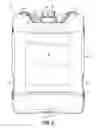
FIG. 3 is a rear perspective view of the present invention in the inverted position;
FIG. 4 is a perspective view similar to FIG. 3 showing the front of the container;
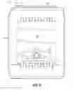
FIG. 5 is a front plan view of the present invention;
FIG. 6 is a side plan view of the present invention;
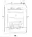
FIG. 7 is a rear plan view of the present invention;
FIG. 8 is a second plan side view of the present invention;
FIG. 9 is an overhead plan view of the present invention;
FIG. 10 is a bottom plan view of the present invention;
FIG. 11 is a perspective view of the present invention in its environment; and
FIG. 12 is an exploded view showing portions of the container with the dispensing system.
DETAILED DESCRIPTION OF THE INVENTION
As shown in FIG. 1, the present invention is a rigid plastic container10 particularly suitable for use in storing moisture-sensitive materials and, in particular, for storing moisture-sensitive materials which can be fed into a gravity dispenser. These may be components (polyols and polyisocyanates) of a polyurethane adhesive such as those used in roofing applications. The container 10 is formed from a rigid plastic material. By rigid, it is simply meant that the present invention is self-supporting and, when compressed, will act to retain its prior form.
The present invention can be formed from a variety of different plastics, preferably a thermoplastic which is suitable for blow molding. The plastic must have a low permeability to moisture. Typically, such materials include high density polyethylene, medium density polyethylene, polypropylene, poly(tetrafluoroethylene) and poly (vinyledene chloride). Although the overall wall thickness will vary, depending upon the plastic used and the design, the wall thickness will generally be from about 0.025″ to about 0.090″ and more particularly from about 0.050″ to about 0.075″. The container should have a very low moisture vapor permeation rate, generally 0.015 US perms or less. The container can be formed by well-known methods such as blow molding, injection molding and rotational molding.
The container 10 is intended to be used with a gravity-fed dispenser, an exemplary one of which is disclosed in U.S. Pat. No. 8,167,170, the disclosure of which is hereby incorporated by reference. Further, an exemplary dispenser 12 is shown in FIG. 11.
The container 10 includes a top surface 14 having an outlet port 16 and a bottom surface 18 with a vent port 20. The terms “top” and “bottom” in this application refer to the container while it is being stored and/or transported. In use, the containers are inverted so the top surface or wall 14 faces downwardly. As shown, the top 14 includes a handle 15 which allows the container 10 to be easily grasped and carried.
The container 10 further includes four side walls 22, 24, 26 and 28 which connect the top surface 14 and the bottom surface 18. The container 10 is shown as a cube, however, it can be other shapes such as a cylinder and the like. But for maximizing storage capacity a cube is optimal. As shown, the top surface 14, in addition to handle 15, includes the outlet port 16 which includes a cap 34 attached to an externally-threaded neck 32. The size of the outlet port 16 is designed based on the contents within the container and should be sufficient to allow the material within the container to easily flow by gravity. Typically, it may have a diameter of about 38 mm. The top surface 14 is designed to nest with the bottom surface 18 so these containers 10 can be stacked on each other. As such, top surface 14 includes an upper peripheral ridge 36.
As shown in FIGS. 3 and 4, the vent port 20 through bottom surface18 includes an externally threaded neck 38 and a cap 40. Further, the bottom surface 18 includes a peripheral recessed area 42 designed to receive the upper peripheral ridge36 of top surface 14. Likewise, bottom surface 18 includes a central recessed portion 41 which is designed to receive the handle 15 when the bottom of the first container is stacked on the second container. Thus, the top surface 14 is nestable with the bottom surface 18.
The side walls 22 and 24 include handle recesses 46 and 48 which are designed to allow one to hold the container 10 with the top surface 14 in a downward orientation for positioning on a dispenser. These recesses 46 and 48 extend inwardly from side walls 22 and 24. These are indented far enough to allow for one to easily hold on to the container. Preferably they will be indented from about ¾ of an inch to 2 inches, more likely 1″ to 1½″ to allow one to easily grasp the containers 10 from the sides 22 and 24. These indentations 46 and 48 are generally parallel to the bottom surface 18, making it easier for the individual to hold. Further, hand recess 46 includes a further inner recess 56 which holds an adapter 54 which, as explained below, will allow the outlet port 16 to be connected to the dispenser 12.
In order to use the container 10 and the dispenser 12, the cap 34 is removed from outlet port 16 and the adapter 54 is pulled from recess 56 and is screwed onto the outlet port (see FIG. 12). In turn, a hose 60 leading to a pump (not shown) in dispenser 12 is attached to the adapter 54 via connector 62 and the container 10 is placed on a tray 58 on dispenser 12. The adapter 54 has a first side which mates with outlet port 16 and a second end that mates with connector 62. A second container is placed on tray 58 in the same manner, attached to a separate hose.
Once in place, the caps 40 over the vent ports 20 are removed, allowing air into the container as the adhesive flows into the hoses through gravity. Once the container 10 is emptied, new containers can be put in their place and the old ones either recycled or discarded.
In the event that the entire contents of the container 10 are not used at one time, the vent cap 40 can be placed back on the vent port 20 and the container 10 can be turned to an upright position and the cap 34 is screwed onto the outlet port 16 after the adapter 54 is removed. Thus, the material can be stored overnight and used the next day, if needed.
The containers act to prevent moisture from contaminating its moisture-sensitive contents. Further, the container will withstand extreme storage conditions. The design of the present invention allows for the continuous gravity-fed flow of the contents to a dispenser. Likewise, this design minimizes any moisture that would enter into the container. Finally, the handles and side wall make it easy for one to transport the container to place them in the inverted position on the tray of a dispenser.
This has been a description of the present invention, along with the preferred method of practicing the present invention. However, the invention itself should only be defined by the appended claims, wherein we claim:
Claims
What is claimed is:1. A container having a top wall, bottom wall and side wall connecting said top wall to said bottom wall;
said top wall having a dispensing port;
said side wall having opposed first and second indentations adapted to allow an individual to hold said container with said top wall facing downwardly.
2. The container claimed in claim 1 wherein said top wall has a handle.
3. The container claimed in claim 1 wherein said first and second indentations are at least ¾ inches deep.
4. The container claimed in claim 3 wherein said first and second indentations are parallel to said bottom wall.
5. The container claimed in claim 1 wherein said bottom wall includes a venting port, and said venting port is recessed in said bottom.
6. The container claimed in claim 1 wherein said side wall includes a third indentation holding an adapter which mates with said outlet port.
7. A dispensing system comprising a first container as claimed in claim 1, wherein said dispensing port is attached to a dispenser with said top wall resting on said dispenser, facing downwardly, said dispenser system including a pump adapted to pump dispensed contents of said container.
8. The dispensing system claimed in claim 6 wherein said system includes a second container as claimed in claim 1, wherein said second container is positioned on said dispenser with a dispensing port attached to said dispenser, said top wall resting on said dispenser facing downwardly.
Images & Drawings included:


Sources:
- United States Patent and Trademark Office - verify current appl. status at the USPTO↗
Recent applications in this class:
- » 20240109697 2024-04-04
SEALING MEMBER FOR PACKAGING - » 20190023464 2019-01-24
VENTED CONTAINER AND LID ASSEMBLY FOR PRODUCE - » 20120193265 2012-08-02
Container for smokeless tobacco products - » 20120031907 2012-02-09
Vented Container - » 20080203096 2008-08-28
Venting Container - » 20060151512 2006-07-13
Packaging cover and box - » 20050236413 2005-10-27
Cover assembly for a food container
Recent applications for this Assignee:
- » 20200362205 2020-11-19
Pressure-sensitive PVC cover strip - » 20190376293 2019-12-12
Roof membranes with removable protective sheets - » 20180346765 2018-12-06
Pressure-sensitive PVC cover strip - » 15973955 2019-09-24
Roof membranes with removable protective sheets