FAN BLADE COVER
US20180363680A1
2018-12-20
15/627,079
2017-06-19
Abstract:
A device and method for a cover having a tubal sleeve, a tab, and a securing mechanism. The tubal end includes an open end to permit sliding over a fan blade. The cover includes a tab configured to couple to a surface of the tubal sleeve. The tab extends partially away from the surface. The securing mechanism is configured to at least partially close the open end so as to restrict movement of the tubal sleeve. The tubal sleeve filters the air of particulates. The tab permits remote or distal operation away from the fan. A user can manipulate the cover position by using the tabs to engage a hand of the user or a tool.
Interested in similar patents?
Get notified when new applications in this technology area are published.
Classification:
F04D29/703 » CPC main
Details, component parts, or accessories; Suction grids; Strainers; Dust separation; Cleaning especially adapted for elastic fluid pumps specially for fans, e.g. fan guards
F04D25/088 » CPC further
Pumping installations or systems; Units comprising pumps and their driving means the working fluid being air, e.g. for ventilation Ceiling fans
F04D29/70 IPC
Details, component parts, or accessories Suction grids; Strainers; Dust separation; Cleaning
F04D25/08 IPC
Pumping installations or systems; Units comprising pumps and their driving means the working fluid being air, e.g. for ventilation
F04D29/38 » CPC further
Details, component parts, or accessories; Rotors specially for elastic fluids for axial flow pumps Blades
Description
BACKGROUND
1. Field of the Invention
The present application relates to a sleeve which covers the blades of a ceiling fan, and more particularly a sleeve which can be installed from a remote location.
2. Description of Related Art
A blade cover is a sleeve of material manufactured from various materials in a tubular configuration where one end of the sleeve is closed and the other end of the sleeve is open to allow the sleeve to be mounted on the fan blade. The cover is installed over blades which are attached to a fan designed to be mounted to the ceiling of a building with the purpose of moving air in a specific area. There is a common desire to have the fan blades maintain an attractive decorative effect. Also, it is common for people to want to minimize the amount of dust and allergens in the air.
Various different methods of installing and securing fan blade covers have been imagined and used. For example, these covers typically include a sleeve to wrap around a portion of the fan blade. It is secured to the fan blade using various types of attaching devices, such as an interlocking member, an internal or external strap, an engageable/disengageable overlapping joint, or a conventional drawstring. Of particular note is that with these types of covers, the user is required to be within reach of the fan blade itself. The user's hands are used to manipulate the cover in its desired manner.
Present covers result in some disadvantages. For example, current methods of installing and securing fan blade covers are not useable by users who cannot reach the ceiling fan or operate current fan blade cover designs. These include the elderly, the disabled, and young. Additionally, the location of the ceiling fans (i.e. vaulted ceilings) may necessitate specialized equipment in order to access the ceiling fan, which is equipment most users do not have.
Although strides have been made in securing the fan blade cover the fan blade cover, considerable shortcomings remain. It is desirable to provide a fan blade cover that can be installed by users who are remote from, or unable to physically get close to, the fan blade. Such users could install the fan blade cover without direct manipulation by the user's hands while next to the fan blade. Additionally, it is desirable to provide a fan blade cover which can more easily be operated by individuals with disabilities.
DESCRIPTION OF THE DRAWINGS
The novel features believed characteristic of the application are set forth in the appended claims. However, the application itself, as well as a preferred mode of use, and further objectives and advantages thereof, will best be understood by reference to the following detailed description when read in conjunction with the accompanying drawings, wherein:
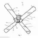
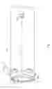
FIG. 1 is a perspective view of a fan blade cover in communication with a ceiling fan according to an embodiment of the present application.
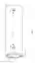
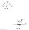
FIG. 2 is an enlarged top view of the fan blade cover of FIG. 1.
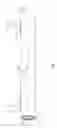
FIG. 3 is a side view of the fan blade cover of FIG. 2.
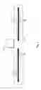
FIG. 4 is an end view of the fan blade cover of FIG. 2.
FIG. 5 is a top view of an alternative embodiment of the fan blade cover of FIG. 2.
FIGS. 6A-6B are side views of an exemplary embodiments of a tab in the fan blade cover of FIGS. 2-3.
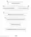
FIG. 7 is a flow chart for the use of the fan blade cover of FIG. 2.
While the device and method of the present application is susceptible to various modifications and alternative forms, specific embodiments thereof have been shown by way of example in the drawings and are herein described in detail. It should be understood, however, that the description herein of specific embodiments is not intended to limit the application to the particular embodiment disclosed, but on the contrary, the intention is to cover all modifications, equivalents, and alternatives falling within the spirit and scope of the process of the present application as defined by the appended claims.
DETAILED DESCRIPTION OF THE PREFERRED EMBODIMENT
Illustrative embodiments of the preferred embodiment are described below. In the interest of clarity, not all features of an actual implementation are described in this specification. It will of course be appreciated that in the development of any such actual embodiment, numerous implementation-specific decisions must be made to achieve the developer's specific goals, such as compliance with system-related and business-related constraints, which will vary from one implementation to another. Moreover, it will be appreciated that such a development effort might be complex and time-consuming but would nevertheless be a routine undertaking for those of ordinary skill in the art having the benefit of this disclosure.
In the specification, reference may be made to the spatial relationships between various components and to the spatial orientation of various aspects of components as the devices are depicted in the attached drawings. However, as will be recognized by those skilled in the art after a complete reading of the present application, the devices, members, apparatuses, etc. described herein may be positioned in any desired orientation. Thus, the use of terms to describe a spatial relationship between various components or to describe the spatial orientation of aspects of such components should be understood to describe a relative relationship between the components or a spatial orientation of aspects of such components, respectively, as the device described herein may be oriented in any desired direction.
The device and method in accordance with the present application overcomes one or more of the above-discussed problems commonly associated with traditional fan blade covers. The fan blade cover of the present application is configured to allow a user to remotely transition the fan blade cover onto a ceiling fan blade. Additionally, the fan blade cover of the present application is configured to assist those with physical disabilities to transition the fan blade cover onto a ceiling fan blade. Further, the fan blade cover in the present application is configured to facilitate the filtering of air. These and other unique features of the device are discussed below and illustrated in the accompanying drawings.
The device and method will be understood, both as to its structure and operation, from the accompanying drawings, taken in conjunction with the accompanying description. Several embodiments of the device may be presented herein. It should be understood that various components, parts, and features of the different embodiments may be combined together and/or interchanged with one another, all of which are within the scope of the present application, even though not all variations and particular embodiments are shown in the drawings. It should also be understood that the mixing and matching of features, elements, and/or functions between various embodiments is expressly contemplated herein so that one of ordinary skill in the art would appreciate from this disclosure that the features, elements, and/or functions of one embodiment may be incorporated into another embodiment as appropriate, unless otherwise described.
The device and method of the present application is illustrated in the associated drawings. The fan blade cover comprises a tubal sleeve which has an open and a closed end. Also, the cover has at least one tab coupled to a surface of the tubal sleeve and which partially extends away from the surface to facilitate locating the tubal sleeve in relation to the fan blade. The cover also includes a securing mechanism configured to at least partially open or close the open end of the cover. Additional features and functions of the device are illustrated and discussed below.
Referring now to the drawings wherein like reference characters identify corresponding or similar elements in form and function throughout the several views. FIG. 1 illustrates a fan blade cover 101 installed on four separate blades of a ceiling fan. It is understood that cover 101 can be designed to be operable with different types of fan blades and is not limited to ceiling fan blades.
In FIG. 1, fan blade cover 101 is illustrated in an operable position in communication with a ceiling fan 86. The ceiling fan 86 includes: fan blade 80, fan blade arm 82, and ceiling fan motor 84. The fan blade 80 is attached to the fan motor 84 by fan blade arm 82. Fan blade cover 101 is seen in communication with the fan blade 80. Cover 101 is translated around a portion of fan blade 80. It is understood that cover 101 may also be in contact with fan blade arm 82. It is also understood that cover 101 may cover all or part of fan blade 80.
Referring now also to FIGS. 2-3 in the drawings, top and side views of fan blade cover 101 is illustrated. Cover 101 includes a tubal sleeve 105, a tab 103, an open end 107, and a securing mechanism 111.
Tubal sleeve 105 includes open end 107 and a closed end 109. Closed end 109 is located opposite from that of open end 107. Open end 107 is large enough to allow the width of blade 80 to pass through open end 107 of tubal sleeve 105. It is understood that the required size of open end 107 will depend on the width and thickness of the fan blades 80. Open end 107 will be closer to fan blade arm 82 than closed end 109 when engaged with fan blade 80.
Sleeve 105 has a top surface 113 and a bottom surface 114. Tab 103 is attached to either top surface 113 or bottom surface 114. The top surface 113 is defined as the part of sleeve 105 which is in communication with the top, or upper part, of fan blade 80. The bottom surface 114 is defined as the part of sleeve 105 which is in communication with the bottom, or lower part, of fan blade 80. Cover 101 may be rotated around blade 80, radially around tubal sleeve axis 121, so as to locate tabs 103 on either relative surface 113 or 114.
Tubal sleeve 105 is configured to filter particles out of the air. It is understood that particles may include items such as dust and allergens for example. Filtration of the air occurs when air passes over and/or through tubal sleeve 105. The weave of tubal sleeve 105 allows air to pass through the material while blocking the passage of air particles. The material of sleeve 105 may include one or more surface treatments that are configured to either assist in the attraction of particulates or prevent the attraction of selected particulates.
Referring now also to FIG. 4 in the drawings, an end view of fan blade cover 101 is illustrated. Although preferably designed to be fully closed, closed end 109 may also include at least one opening. For purposes of clarity, cover 101 is illustrated herein to have a plurality of openings 119. It is understood that opening 119 is sized to be smaller than the corresponding height and width of blade 80. This prevents blade 80 from passing through closed end 109. Opening 119 helps the flow of air exit the interior of sleeve 105, so as to minimize drag on blade 80.
Returning back to FIGS. 2-3, tubal sleeve 105 has securing mechanism 111. Securing mechanism 111 includes a drawstring 112 and is located at or near open end 107. Drawstring 112 selectively restricts and permits the opening of open end 107. Drawstring 112 is in communication with tubal sleeve 105 at open end 107. For example, tubal sleeve 105 may be configured such that there is a tunnel at open end 107 and drawstring 112 is threaded there through. One possible method of restricting open end 107 is by user pulling on drawstring 112, much like the drawstring on a pair of clothing. Additionally, drawstring 112 may have elastic or magnetic properties to assist in restricting open end 107. It is understood that the securing mechanism 111 is not restricted to a type of drawstring, but may include elastic materials (e.g. elastic band) or a magnet (e.g. a magnetic and metal wire). Securing mechanism 111 prohibits cover 101 from translating off of fan blade 80 by restricting the size of open end 107. Securing mechanism 111 can operate between a secured position and an unsecured position. An unsecured position occurs when the diameter of open end 107 is large enough to allow the width and thickness of blade 80 to pass through open end 107. In this position, cover 101 can be translated onto or off of blade 80. A secured position occurs when securing mechanism 111 restricts open end 107 to the point where blade 80 is no longer able to fully pass through open end 107. In this position, cover 101 is restricted from translating onto or off of blade 80.
Tubal sleeve 105 is further configured in a manner to allow it to be translated across fan blade 80, parallel to axis 121, through the use of tab 103. Tab 103 is a relatively thin and narrow piece of material which extends partially away from tubal sleeve 105 a selected distance. Tab 103 has a plurality of ends which are attached to tubal sleeve 105 at a single location 102, thereby forming a loop. The loop is configured to accept manipulation by a user's hand or through a tool (see FIG. 5). One tab 103 is located adjacent open end 107 and a second tab 103 is located adjacent end 109. The ends of tabs 103 are attached to tubal sleeve 105 by any common fastening method, such as stitching, an adhesive, or a fastener. The ends can be orientated towards open end 107, closed end 109, or any orientation there between. It is understood that cover 101 may include tabs 103 at any location on sleeve 105 and is not herein restricted to the locations shown. The ideal locations are those that best facilitate the manipulation of tubal sleeve 105 on fan blade 80.
As stated previously, tab 103 can be used by hand or tool to manipulate cover 101 on fan blade 80. Manipulation includes any movement of tubal sleeve 105. For example, any movement parallel or perpendicular to axis 121. Also, tab 103 allows for the manipulation of cover 101 without the need to touch surface of tubal sleeve 105 and/or disturb air particles deposited on tubal sleeve 105.
Referring now also to FIG. 5 in the drawings, an alternative embodiment of fan blade cover 101 is illustrated. Fan blade cover 201 is depicted in FIG. 5. Cover 201 is similar in form and function to that of cover 101 except as herein noted. Like reference characters identify corresponding or similar elements in form and function between cover 101 and cover 201. In this embodiment, multiple tabs 103 are located adjacent open end 107. Additionally, tool 213 is depicted in communication with tabs 103 adjacent to open end 107.
Tool 213 is any item or object operated by the user to enhance grip and/or lengthen the reach of the user. Tool 213 may be used with either cover 101 or cover 201. One part of tool 213 will be in communication with at least one tab 103 during manipulation of tubal sleeve 105. Through use of tool 213, a user would be able to transfer a force on the tool to tab 103 on tubal sleeve 105. Tool 213 allows a user to use cover 101/201 on a fan which may be out of user's reach. It is understood that FIG. 5 and tool 213 do not represent all the tools a user may use.
In operation, tool 213 is configured to pass through the loop of at least one tab 103. Tool 213 is operable through any tab 103 and is likewise configured to be removable to facilitate different engagement orientations with tabs 103. As seen in FIG. 5, tool 213 is slid through the loop of separate tabs 103 located adjacent open end 107. It is understood that a tool could also communicate with tab 103 in any other commonly used manner, including grabbing the tab or using magnetism. Use along tabs 103 at open end 107 is ideally suited for installing cover 201 onto blade 80. Use with tab 103 at closed end 109 is ideally suited for removing cover 201 from blade 80. It is understood that use of any number of tabs 103 located in any of the positions on sleeve 105 may be used to assist in proper positioning relative to blade 80.
Referring now also to FIGS. 6A-6B, demonstrating some alternate styles of tab 103. As seen in FIGS. 2-3, both ends of tab 103 is attached to tubal sleeve at location 102. As configured, tab 103 may not lay down flat while fan 86 is in operation; increasing drag on fan blade 80. Therefore, alternate configurations of tab 103 may be used. Tab 103a is similar to tab 103 except that tab 103a is attached to tubal sleeve 105 at two locations 102. Tab 103a would also extend partially away from tubal sleeve 105. While tab 103a would not lay down completely flush with tubal sleeve 105, tab 103a would have a lower profile and less drag on fan blade 80.
In particular with FIG. 6B, only one end of tab 103b is attached to tubal sleeve 105 at one location 102. The other end of tab 103b would extend partially away from tubal sleeve 105. As depicted, Tab 103b would have aperture 117 in the portion of tab 103b which extends away from tubal sleeve 105. Aperture 117 is a hole or slot in tab 103b which would allow user to use a tool in a similar manner as tab 103. While fan 86 is in use, tab 103b would lay down flush with blade 80, decreasing drag, where tab 103 may not. It is understood that tabs 103, 103a, and 103b do not represent all the styles of tabs which may be used to facilitate the translation of cover 101 on fan blade 80.
Referring now also to FIG. 7, demonstrating the method for operation of cover 101. Obtain a fan blade cover appropriate for the fan blade, step 301. User chooses to either use hands to manipulate the tabs, step 303, or use a tool to manipulate tabs, step 305. User then maneuvers the cover's open end, either by arm or tool, adjacent to the fan blade, step 307. User then translates the tubal sleeve along the length of fan blade, step 309. It is understood that a tool would apply the force on the tab necessary to translate the cover around a portion of the fan blade. User can optionally rotate the cover as desired, step 311, such that the tabs can be switched between an upper surface or lower surface of the fan blade. Step 311 could facilitate optimal tab placement for fan blade cover manipulation or operation of fan while cover is in communication with the fan blade. User then engages the securing mechanism, either by hand, tool, or other design, to prevent the removal of the cover from the fan blade during fan operation, step 313. The securing mechanism would be configured to at least partially close the open end of the tubal sleeve. The securing mechanism would also be designed in such a manner that it could be disengaged by use of a tool or by hand; whereupon the diameter of the open end would be larger than the width and thickness of the fan blade. Fan blade cover could be then be manipulated or removed from the fan blade through use of tabs by hand or by tool.
The current application has many advantages over the prior art including at least the following: (1) tabs which increase the ability of the handicapped users to manipulate the cover; (2) users would be able to use tabs and tools to increase their reach so that a cover can be installed/removed on distant or difficult to access fan blades; (3) tubal sleeve would filter desired particles out of the air; and (4) tabs would minimize the disturbance of deposited air particles while manipulating the tubal sleeve.
The particular embodiments disclosed above are illustrative only and are not intended to be exhaustive or to limit the invention to the precise form disclosed, as the embodiments may be modified and practiced in different but equivalent manners apparent to those skilled in the art having the benefit of the teachings herein. It is therefore evident that the particular embodiments disclosed above may be altered or modified, and all such variations are considered within the scope and spirit of the application. Accordingly, the protection sought herein is as set forth in the description. It is apparent that an application with significant advantages has been described and illustrated. Although the present application is shown in a limited number of forms, it is not limited to just these forms, but is amenable to various changes and modifications without departing from the spirit thereof.
Claims
What is claimed is:1. A cover, comprising:
a tubal sleeve having an open end;
a tab coupled to a surface of the tubal sleeve, the tab extending partially away from the surface;
a securing mechanism configured to at least partially close the open end.
2. The cover in claim 1, wherein the tubal sleeve includes a closed end opposite the open end.
3. The cover in claim 2, wherein the closed end includes at least one opening.
4. The cover in claim 1, wherein the tubal sleeve is configured to filter air particulates out of the air.
5. The cover in claim 1, wherein the tab includes an aperture.
6. The cover in claim 1, wherein the tab includes a plurality of ends, the plurality of ends are attached to the surface at separate locations.
7. The cover in claim 1, wherein the tab includes a plurality of ends, the plurality of ends attached to the surface at the same location.
8. The cover in claim 1, wherein the surface from which the tab extends is a top surface of the tubal sleeve.
9. The cover in claim 1, wherein the surface from which the tab extends is a bottom surface of the tubal sleeve.
10. The cover in claim 1, wherein the securing mechanism can operate between a secured position and an unsecured position.
11. A method of covering a fan blade, comprising:
obtaining a fan blade cover including:
a tubal sleeve having an open end;
a tab located on a surface of the tubal sleeve, the tab extending partially away from the surface; and
a securing mechanism configured to at least partially close the open end;
repositioning the cover adjacent the fan blade;
translating the tubal sleeve along the length of the fan blade via manipulation of the tab; and
securing the tubal sleeve to the fan blade by engaging the securing mechanism.
12. The method of claim 11, further comprising: rotating the sleeve relative to the fan blade.
13. The method of claim 11, further comprising: removing the cover by disengaging the securing mechanism; and applying a force to the tab engaging the tab.
14. The method of claim 11, further comprising: opening the open end of the tubal sleeve.
15. The method of claim 11, further comprising: engaging the securing mechanism to prevent removal of the cover from the fan blade.
16. The method of claim 15, further comprising: the tool engages the securing mechanism to prevent removal.
17. The method of claim 11, further comprising:
obtaining a tool configured to engage the tab; and
operating the tool to apply a force to the tab so as to translate the cover around a portion of the fan blade.
18. The method of claim 17, further comprising: the tool extends the reach of the user.
19. The method of claim 18, further comprising: use of the tool permits the user to operate the cover while remote from the fan blade.
20. A cover for a fan blade, comprising:
a tubal sleeve having an open end and a closed end, the closed end located opposite the open end, the tubal sleeve surrounding a portion of the fan blade;
a first tab located on a surface of the tubal sleeve, the tab extending partially away from the surface and located adjacent the open end;
a second tab located on the surface of the tubal sleeve adjacent to the closed end, the second tab configured to extend away from the surface; and
a securing mechanism configured to selectively restrict movement of the tubal sleeve along the fan blade by changing the relative dimension of the open end, the securing mechanism located at the open end;
wherein the first tab and the second tab facilitate remote manipulation of the tubal sleeve on the fan blade.
Images & Drawings included:

Sources:
- United States Patent and Trademark Office - verify current appl. status at the USPTO↗
Similar patent applications:
- » 20180017085
FAN BLADE COVER SYSTEM - » 20170343007
Mechanically retained fan blade cover - » 20170023009
Fan blade with segmented fan blade cover - » 20170074282
CEILING FAN BLADE COVER SYSTEM - » 20120237351
RETENTION FOR BONDED HOLLOW FAN BLADE COVER - » 20170023007
Fan blade with integrated composite fan blade cover - » 20150330399
Scented Fan Blade Covers and Related Methods - » 20120224967
Elastic and Dust-Clinging Fan Blade Cover and Scent Pocket - » 20050152783
Fan blade cover with ornament - » 20200254588
Infinitely directional translating clamp for welding a fan blade cover
Recent applications in this class:
- » 20250163939 2025-05-22
FLUSH-MOUNT FAN GRILLE - » 20250129798 2025-04-24
FAN ASSEMBLY WITH A REMOVABLE FILTER ASSEMBLY - » 20250122892 2025-04-17
ELECTRONIC DEVICES AND CLEANING METHOD THEREOF AND DETERMINATION METHOD OF FAN STATUS DETERMINATION MODEL THEREOF - » 20250101995 2025-03-27
Ceiling Fan Filter - » 20250067280 2025-02-27
VENTILATION AND PROTECTION GRID FOR FAN MODULE - » 20240352949 2024-10-24
CEILING FAN BLADE DEVICE FOR CAPTURING AIRBORNE PARTICLES - » 20240309889 2024-09-19
Fan assembly with a removable filter assembly - » 20240263647 2024-08-08
GUIDING GRID - » 20240200577 2024-06-20
Blower vacuum - » 20240102492 2024-03-28
Fan guard