Device and method for lateral guidance assistance for a road vehicle
US20180366002A1
2018-12-20
16/110,375
2018-08-23
✅ Patent granted
US 10,885,789 B2
2021-01-05
-
-
Shirley Lu
Crowell & Moring LLP
2038-08-23
Abstract:
A device for lateral guidance assistance for a vehicle includes a programmable electronic control unit and a plurality of distance sensors configured to capture obstacles to a side of and/or behind the vehicle within one or more defined warning regions. The device also includes an optical sensor device configured to capture lane markings and/or a lane width of a current lane of the vehicle and/or of a neighboring lane of the vehicle. The programmable electronic control unit is configured such that at least one of the defined warning regions is shifted based on a detected lane change to a new lane.
Inventors:
- Matthias Beck 3 🇩🇪 Muenchen, Germany
- Tobias Rothmund 2 🇩🇪 Oberschleissheim, Germany
- Tom Kasseckert 2 🇩🇪 Mering, Germany
- Matthias Beck 4 🇩🇪 Munich, Germany
Assignee:
- BAYERISCHE MOTOREN WERKE AKTIENGESELLSCHAFT 3,338 🇩🇪 Munich, Germany
Applicant:
Interested in similar patents?
Get notified when new applications in this technology area are published.
Classification:
G08G1/167 » CPC main
Traffic control systems for road vehicles; Anti-collision systems Driving aids for lane monitoring, lane changing, e.g. blind spot detection
B60W2420/42 » CPC further
Indexing codes relating to the type of sensors based on the principle of their operation Image sensing, e.g. optical camera
B60W30/18 IPC
Purposes of road vehicle drive control systems not related to the control of a particular sub-unit, e.g. of systems using conjoint control of vehicle sub-units, or advanced driver assistance systems for ensuring comfort, stability and safety or drive control systems for propelling or retarding the vehicle Propelling the vehicle
G01S2013/93274 » CPC further
Systems using the reflection or reradiation of radio waves, e.g. radar systems; Analogous systems using reflection or reradiation of waves whose nature or wavelength is irrelevant or unspecified; Radar or analogous systems specially adapted for specific applications for anti-collision purposes of land vehicles; Sensor installation details on the side of the vehicles
G08G1/16 IPC
Traffic control systems for road vehicles Anti-collision systems
B62D15/02 IPC
Steering not otherwise provided for Steering position indicators ; Steering position determination; Steering aids
B60W30/18163 » CPC further
Purposes of road vehicle drive control systems not related to the control of a particular sub-unit, e.g. of systems using conjoint control of vehicle sub-units, or advanced driver assistance systems for ensuring comfort, stability and safety or drive control systems for propelling or retarding the vehicle; Propelling the vehicle related to particular drive situations Lane change; Overtaking manoeuvres
B60W30/095 » CPC further
Purposes of road vehicle drive control systems not related to the control of a particular sub-unit, e.g. of systems using conjoint control of vehicle sub-units, or advanced driver assistance systems for ensuring comfort, stability and safety or drive control systems for propelling or retarding the vehicle predicting or avoiding probable or impending collision Predicting travel path or likelihood of collision
B60Q9/008 » CPC further
Arrangement or adaptation of signal devices not provided for in one of main groups - , e.g. haptic signalling for anti-collision purposes
B60W50/14 » CPC further
Details of control systems for road vehicle drive control not related to the control of a particular sub-unit, e.g. process diagnostic or vehicle driver interfaces; Interaction between the driver and the control system Means for informing the driver, warning the driver or prompting a driver intervention
B62D15/025 » CPC further
Steering not otherwise provided for; Steering position indicators ; Steering position determination; Steering aids Active steering aids, e.g. helping the driver by actively influencing the steering system after environment evaluation
G08G1/165 » CPC further
Traffic control systems for road vehicles; Anti-collision systems for passive traffic, e.g. including static obstacles, trees
B60W2554/00 » CPC further
Input parameters relating to objects
G01S2013/93272 » CPC further
Systems using the reflection or reradiation of radio waves, e.g. radar systems; Analogous systems using reflection or reradiation of waves whose nature or wavelength is irrelevant or unspecified; Radar or analogous systems specially adapted for specific applications for anti-collision purposes of land vehicles; Sensor installation details in the back of the vehicles
B60Q9/00 IPC
Arrangement or adaptation of signal devices not provided for in one of main groups - , e.g. haptic signalling
G01S13/931 IPC
Systems using the reflection or reradiation of radio waves, e.g. radar systems; Analogous systems using reflection or reradiation of waves whose nature or wavelength is irrelevant or unspecified; Radar or analogous systems specially adapted for specific applications for anti-collision purposes of land vehicles
Description
CROSS REFERENCE TO RELATED APPLICATIONS
This application is a continuation of PCT International Application No. PCT/EP2017/053711, filed Feb. 17, 2017, which claims priority under 35 U.S.C. § 119 from German Patent Application No. 10 2016 202 830.8, filed Feb. 24, 2016, the entire disclosures of which are herein expressly incorporated by reference.
BACKGROUND AND SUMMARY OF THE INVENTION
The invention relates to a device and a method for lateral guidance assistance for a road vehicle.
Known lateral guidance driver assistance systems provide the vehicle driver with assistance, for example during a lane change, in order to reduce the risk of a possible collision, in particular with third-party vehicles in the blind spot.
In known systems, in particular for lane change warning or blind spot warning, the warning region for triggering a lane change warning by the vehicle is defined as two lateral regions permanently associated with the vehicle position. In other words, warning regions are fixed geometrical regions in the vehicle coordinate system. In the event of a lane change, the warning regions are taken along with the vehicle coordinate system irrespective of the situation. A permanently defined warning region according to the prior art can therefore result in incorrect or false warnings in isolated situations. If the vehicle carries out a lane change, this lane change is not detected when determining the warning regions over the trajectory traveled, but rather is interpreted as cornering.
The invention is based on the object of providing a driver assistance system for lateral guidance assistance for a road vehicle, which system avoids false warnings, in particular.
According to the invention, the object is achieved by means of the features of the independent claims, whereas preferred developments of the invention are stated in the dependent claims.
The invention fundamentally relates to a device and a method for lateral guidance assistance for a road vehicle, wherein
- the at least one warning region is shifted,
- using a programmable electronic control unit,
- using distance sensors for capturing obstacles to the side of and/or behind the vehicle within at least one defined warning region and
- using an optical sensor device at least for capturing the road markings and/or the lane width of the current lane and/or for capturing the road markings and/or the lane width at least of the nearest neighboring lane,
- on the basis of a detected lane change, that is to say is not taken along, but rather is shifted.
The invention is based on the idea of shifting at least one warning region to a defined time of a lane change that has been detected as completed.
The lane change is preferably detected using a camera system. The time of a detected lane change is preferably defined as follows or a lane change is considered to be carried out if:
- the center of the front axle crosses the lane marking and/or
- the center of the rear axle crosses the lane marking and/or
- the center of the front axle is in a tolerance band around the lane marking and/or
- the center of the rear axle is in a tolerance band around the lane marking and/or
- the vector of the direction of movement points to the neighboring lane.
In one development of the invention, at least one warning region is also adapted with respect to the width of the new neighboring lane if necessary. The time and the direction of the respective lane change are preferably stored in order to define the warning region according to the corresponding lanes. A corresponding procedure should be followed in the case of a plurality of successive lane change operations.
Example: in the event of a lane change to the left, the new right-hand warning region is shifted to the lane which has been left. For the new left-hand warning region, no information relating to lane markings at the left-hand edge of the road has possibly been stored for the route which has already been covered. In order to nevertheless obtain good functional quality in this case, the approach of basing the new left-hand lane markings on the lane width is used in the event of a lane change. The procedure should be the same for a lane change to the right.
Advantages of the Invention
- Customer-relevant improvement in the system performance;
- Reduction in false and incorrect warnings as a result of appropriate assignment of the warning regions during or directly after the lane change;
- No additional outlay on the hardware and sensor system.
Other objects, advantages and novel features of the present invention will become apparent from the following detailed description of one or more preferred embodiments when considered in conjunction with the accompanying drawings.
BRIEF DESCRIPTION OF THE DRAWINGS
One exemplary embodiment of the invention is illustrated in the drawing and is described in more detail below.
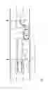
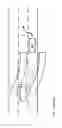
FIG. 1: shows a schematic illustration of an exemplary traffic situation with two motor vehicles which are spaced apart from one another in the direction of travel and are traveling in a laterally offset manner with respect to one another, wherein the vehicle traveling in front is equipped with the device according to the invention for lateral guidance assistance for the purpose of explaining the invention.
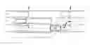
FIG. 2: shows, in comparison with FIG. 1, an exemplary embodiment which is known.
DETAILED DESCRIPTION OF THE DRAWINGS
The prior art and the problem associated therewith are first of all explained in connection with FIG. 2, as described below.
FIG. 2 illustrates a road, for example a highway, having three lanes S1, S2 and S3. The vehicle equipped with the driver assistance system (subsequently) according to the invention is represented by the vehicle 1. A third-party vehicle approaching from the rear is represented by the vehicle 5.
The vehicle 1 carries out a first lane change from the lane S2 to the lane S1. The warning regions W1 and W2, which are defined over the trajectory traveled according to the prior art, are illustrated using dashed lines. The third-party vehicle 5 is currently not in the warning region W1 or W2. In the case of warning regions which are permanently fixed to the vehicle coordinate system, they are “taken along” with the vehicle 1 independently of the vehicle environment, as if the vehicle 1 were only traveling along a bend. If the vehicle 1 then carries out a second lane change from the lane S1 back to the lane S2, the third-party vehicle 5 could enter the warning region W1 of the vehicle 1 too late.
FIG. 1 illustrates the vehicle 1 having a programmable electronic control unit 2 and having distance sensors 3 for capturing obstacles to the side of and/or behind the vehicle 1 within a defined warning region W1 on the driver's side and within a defined warning region W2 on the passenger side (already prior art). In FIG. 1, the vehicle 1 also has a front-facing and/or rear-facing optical sensor device 4 for capturing at least the lane markings and possibly also for capturing the respective lane width of the current lane and/or for capturing the respective lane width at least of the nearest neighboring lane.
The control unit 2 is in the form of an accordingly programmed functional module (computer program product), for example.
The first lane change of the vehicle 1 is carried out from the lane S2 to the lane S1 at the time t1. The warning region W1 is in lane S3 before this lane change, and the warning region W2 is in the lane S1 before this lane change. After detecting that the road marking between the lanes S2 and S1 has been driven over at the time t1, for example if the center of the rear axle crosses the lane marking here, the warning region W1 is suddenly shifted to the lane S2 and warning region W2 is shifted to the hard shoulder S0, for example (=>see W1′ and W2′).
The second lane change of the vehicle 1 is carried out from the lane S1 back to the lane S2 at the time t2. After detecting that the road marking between the lanes S2 and S1 has been driven over at the time t2, the warning region W1′ is suddenly changed to the lane S3 again and the warning region W2′ is changed to the lane S1.
As a result of this method according to the invention, the third-party vehicle 5 is always detected in good time in the warning region W1 or W1′ if necessary.
In the case of different or changing lane widths in particular, the warning region(s) W1 (or W1′) and/or W2 (or W2′) is/are preferably changed as follows in a first alternative with respect to its/their width and with respect to its/their distance to the vehicle 1:
If a particular width is captured in the nearest neighboring lane, the width of the warning region is adapted to this width and the distance between the warning region and the vehicle 1 is preferably also adapted to a corresponding distance.
Alternatively or additionally, in particular if the lane width at least of the nearest neighboring lane cannot be captured by means of discernible boundaries (for example in the case of a missing lane marking and guardrail), the warning region is preferably changed as above, but with the difference that the widths of the neighboring lane are inferred from the respectively detected widths of the lane.
The foregoing disclosure has been set forth merely to illustrate the invention and is not intended to be limiting. Since modifications of the disclosed embodiments incorporating the spirit and substance of the invention may occur to persons skilled in the art, the invention should be construed to include everything within the scope of the appended claims and equivalents thereof.
Claims
What is claimed is:1. A device for lateral guidance assistance for a vehicle, the device comprising:
a programmable electronic control unit;
a plurality of distance sensors configured to capture obstacles to a side of and/or behind the vehicle within one or more defined warning regions; and
an optical sensor device configured to capture lane markings and/or a lane width of a current lane of the vehicle and/or of a neighboring lane of the vehicle,
wherein the programmable electronic control unit is configured such that at least one of the defined warning regions is shifted based on a detected lane change to a new lane.
2. The device as claimed in claim 1, wherein the at least one of the defined warning regions is shifted according to the new lane based on the detected lane change.
3. The device as claimed in claim 1, wherein the at least one of the defined warning regions that is shifted is changed based at least in part on a width of the new lane.
4. The device as claimed in claim 2, wherein the at least one of the defined warning regions that is shifted is changed based at least in part on a width of the new lane.
5. The device as claimed in claim 1, wherein the control unit is configured to determine that the detected lane change is completed when:
a center of a front axle of the vehicle crosses at least one of the captured lane markings,
a center of a rear axle of the vehicle crosses at least one of the captured lane markings,
the center of the front axle is in a tolerance band around at least one of the captured lane markings,
the center of the rear axle is in a tolerance band around at least one of the captured lane markings, and/or
a vector of a direction of movement of the vehicle points to the neighboring lane.
6. The device as claimed in claim 2, wherein the control unit is configured to determine that the detected lane change is completed when:
a center of a front axle of the vehicle crosses at least one of the captured lane markings,
a center of a rear axle of the vehicle crosses at least one of the captured lane markings,
the center of the front axle is in a tolerance band around at least one of the captured lane markings,
the center of the rear axle is in a tolerance band around at least one of the captured lane markings, and/or
a vector of a direction of movement of the vehicle points to the neighboring lane.
7. The device as claimed in claim 3, wherein the control unit is configured to determine that the detected lane change is completed when:
a center of a front axle of the vehicle crosses at least one of the captured lane markings,
a center of a rear axle of the vehicle crosses at least one of the captured lane markings,
the center of the front axle is in a tolerance band around at least one of the captured lane markings,
the center of the rear axle is in a tolerance band around at least one of the captured lane markings, and/or
a vector of a direction of movement of the vehicle points to the neighboring lane.
8. A method for lateral guidance assistance for a road vehicle comprising:
capturing, by a plurality of distance sensors of the vehicle, obstacles to a side of and/or behind the vehicle within one or more defined warning region;
capturing, by an optical sensor device of the vehicle, lane markings and/or a lane width of a current lane of the vehicle and/or of a neighboring lane of the vehicle; and
shifting, by a programmable electronic control unit of the vehicle, at least one of the defined warning regions based on a detected lane change to a new lane.
9. The method as claimed in claim 8, wherein the at least one of the defined warning regions is shifted according to the new lane based on the detected lane change.
10. The method as claimed in claim 8, wherein the at least one of the defined warning regions that is shifted is changed based at least in part on a width of the new lane.
11. The method as claimed in claim 9, wherein the at least one of the defined warning regions that is shifted is changed based at least in part on a width of the new lane.
12. The method as claimed in claim 8, further comprising determining, by the programmable electronic control unit, that the detected lane change is completed when:
a center of a front axle of the vehicle crosses at least one of the captured lane markings,
a center of a rear axle of the vehicle crosses at least one of the captured lane markings,
the center of the front axle is in a tolerance band around at least one of the captured lane markings,
the center of the rear axle is in a tolerance band around at least one of the captured lane markings, and/or
a vector of a direction of movement of the vehicle points to the neighboring lane.
13. The method as claimed in claim 9, further comprising determining, by the programmable electronic control unit, that the detected lane change is completed when:
a center of a front axle of the vehicle crosses at least one of the captured lane markings,
a center of a rear axle of the vehicle crosses at least one of the captured lane markings,
the center of the front axle is in a tolerance band around at least one of the captured lane markings,
the center of the rear axle is in a tolerance band around at least one of the captured lane markings, and/or
a vector of a direction of movement of the vehicle points to the neighboring lane.
14. The method as claimed in claim 10, further comprising determining, by the programmable electronic control unit, that the detected lane change is completed when:
a center of a front axle of the vehicle crosses at least one of the captured lane markings,
a center of a rear axle of the vehicle crosses at least one of the captured lane markings,
the center of the front axle is in a tolerance band around at least one of the captured lane markings,
the center of the rear axle is in a tolerance band around at least one of the captured lane markings, and/or
a vector of a direction of movement of the vehicle points to the neighboring lane.
15. A motor vehicle having a device configured to provide lateral guidance assistance for the vehicle, the device comprising:
a programmable electronic control unit;
a plurality of distance sensors configured to capture obstacles to a side of and/or behind the vehicle within one or more defined warning regions; and
an optical sensor device configured to capture lane markings and/or a lane width of a current lane of the vehicle and/or of a neighboring lane of the vehicle,
wherein the control unit is configured such that at least one of the defined warning regions is shifted based on a detected lane change to a new lane.
Images & Drawings included:
Sources:
- United States Patent and Trademark Office - verify current appl. status at the USPTO↗
Similar patent applications:
- » 20240416942
Method for Assisting a User of a Vehicle During Automated Lateral Guidance of the Vehicle on a Road Having Multiple Lanes, Computing Device, and Driver Assistance System - » 20250153728
Method for Assisting a User of a Vehicle During an Automated Lateral Guidance of the Vehicle on a Road With a Branch, Computing Device and Driver Assistance System
Recent applications in this class:
- » 20250292687 2025-09-18
ENVIRONMENTAL TEXT PERCEPTION AND TOLL EVALUATION USING VISION LANGUAGE MODELS - » 20250292686 2025-09-18
VEHICLE SAFETY SYSTEM WITH 360-DEGREE VIEW, BLIND SPOT MITIGATION, AND DRIVE ASSIST FEATURES - » 20250279002 2025-09-04
IN-VEHICLE DEVICE, COMMUNICATION METHOD, AND COMMUNICATION PROGRAM - » 20250265932 2025-08-21
DRIVE ASSIST APPARATUS - » 20250239164 2025-07-24
METHOD AND APPARATUS FOR ASSISTING VEHICLE LANE CHANGE - » 20250209918 2025-06-26
VEHICLE-ROAD COLLABORATIVE LANE-CHANGING RISK ASSESSMENT METHOD BASED ON COORDINATE TRANSFORMATION - » 20250166510 2025-05-22
Blind Spot Estimation Device, Traveling Environment Generation Device, Vehicle Control Device, and Vehicle - » 20250157337 2025-05-15
COMPUTER SYSTEM AND METHOD FOR TURN INDICATOR CANCELLATION - » 20250148918 2025-05-08
Actively Modifying a Field of View of an Autonomous Vehicle in View of Constraints - » 20250148917 2025-05-08
DRIVER ASSIST CONTROL DEVICE, DRIVER ASSIST METHOD, AND NONTRANSITORY COMPUTER STORAGE MEDIUM
Recent applications for this Assignee:
- » 20250236179 2025-07-24
METHOD FOR OPERATING A BRAKE CONTROL SYSTEM, BRAKE CONTROL SYSTEM, COMPUTER PROGRAM, AND COMPUTER-READABLE STORAGE MEDIUM - » 20250109792 2025-04-03
Mounting assembly for a coupler mechanism of a motor vehicle - » 20250077042 2025-03-06
Method for increasing safety during the operation of a device - » 20250042351 2025-02-06
Arrangement for Holding a Sidewall Element on a Bodyshell Part of a Vehicle, Bracket and Vehicle - » 20250026428 2025-01-23
Handlebar Assembly for a Motor Vehicle, and Motor Vehicle Having a Handlebar Assembly of This Kind - » 20250020305 2025-01-16
Decorative element for a motor vehicle, and production method for a decorative element - » 20250001843 2025-01-02
Motor Vehicle With a Side Door - » 20240426445 2024-12-26
Motor Vehicle Lighting Module - » 20240383554 2024-11-21
Leaning vehicle - » 20240383416 2024-11-21
Motor vehicle having a plurality of control devices which provide different vehicle functions in the motor vehicle and method for configuring the control devices and control device