Dual purpose threaded insert/compression limiter
US20190024696A1
2019-01-24
15/654,675
2017-07-19
✅ Patent granted
US 10,683,885 B2
2020-06-16
-
-
Gary W Estremsky
Harness, Dickey & Pierce, P.L.C.
2038-09-21
Abstract:
A cover member includes a body member made of a composite material and including a mounting flange. A plurality of compression limiters are disposed in the mounting flange, the compression limiters have a predetermined thickness and an internally threaded aperture therein. The dual function compression limiters eliminate the need for separate threaded inserts. With the dual function compression limiter, every bolt location provides a potential location for a jack screw.
Inventors:
- Marc L. Friedrich 6 🇺🇸 Rochester Hills, MI, United States
- Martin K. SCOTT 3 🇺🇸 Waterford, MI, United States
- Kevin W. Herrala 5 🇺🇸 Grand Blanc, MI, United States
Assignee:
- GM GLOBAL TECHNOLOGY OPERATIONS LLC 17,253 🇺🇸 Detroit, MI, United States
Applicant:
Interested in similar patents?
Get notified when new applications in this technology area are published.
Classification:
F02B77/088 » CPC further
Component parts, details or accessories, not otherwise provided for; Safety, indicating or supervising devices relating to tightness
F16B21/183 » CPC main
Means for preventing relative axial movement of a pin, spigot, shaft or the like and a member surrounding it ; Stud-and-socket releasable fastenings by separate parts with grooves or notches in the pin or shaft with circlips or like resilient retaining devices, i.e. resilient in the plane of the ring or the like ; Details internal, i.e. with spreading action
F02F7/006 » CPC further
Casings, e.g. crankcases or frames Camshaft or pushrod housings
F02F2007/0041 » CPC further
Casings, e.g. crankcases or frames; Construction Fixing Bolts
F16B31/021 » CPC further
Screwed connections specially modified in view of tensile load; Break-bolts for indicating or limiting tensile load by means of a frangible part
F16B33/004 » CPC further
Features common to bolt and nut Sealing; Insulation
F16B5/025 » CPC further
Joining sheets or plates, e.g. panels, to one another or to strips or bars parallel to them by means of fastening members using screw-thread specially designed to compensate for misalignement or to eliminate unwanted play
F16B41/002 » CPC further
Measures against loss of bolts, nuts, or pins; Measures against unauthorised operation of bolts, nuts or pins Measures against loss of bolts, nuts or pins
F16B43/02 IPC
Washers or equivalent devices; Other devices for supporting bolt-heads or nuts with special provisions for engaging surfaces which are not perpendicular to a bolt axis or do not surround the bolt
F16B21/18 IPC
Means for preventing relative axial movement of a pin, spigot, shaft or the like and a member surrounding it ; Stud-and-socket releasable fastenings by separate parts with grooves or notches in the pin or shaft with circlips or like resilient retaining devices, i.e. resilient in the plane of the ring or the like ; Details
F02F7/00 IPC
Casings, e.g. crankcases or frames
F16B19/02 » CPC further
Bolts without screw-thread; Pins, including deformable elements ; Rivets Bolts or sleeves for positioning of machine parts, e.g. notched taper pins, fitting pins, sleeves, eccentric positioning rings
F16B39/30 » CPC further
Locking of screws, bolts or nuts in which the locking takes place during screwing down or tightening by special members on, or shape of, the nut or bolt Locking exclusively by special shape of the screw-thread
F16B41/00 IPC
Measures against loss of bolts, nuts, or pins; Measures against unauthorised operation of bolts, nuts or pins
F16B33/00 IPC
Features common to bolt and nut
F02B77/08 IPC
Component parts, details or accessories, not otherwise provided for Safety, indicating or supervising devices
F16B5/02 IPC
Joining sheets or plates, e.g. panels, to one another or to strips or bars parallel to them by means of fastening members using screw-thread
F16B31/02 IPC
Screwed connections specially modified in view of tensile load; Break-bolts for indicating or limiting tensile load
Description
FIELD
The present disclosure relates to a compression limiter for a composite cover that includes internal threads for receiving a jack screw to assist in removing the cover.
BACKGROUND
This section provides background information related to the present disclosure which is not necessarily prior art.
Current composite pan/cover assemblies 110 have metallic compression limiters 112 at each bolt hole 114 for receiving a mounting bolt 116, as shown in FIG. 4. The pan/cover assemblies 110 also include a metallic threaded insert 116 used with a jack screw 118 to help break the sealant bond and separate the pan/cover assembly 110, as shown in FIG. 5.
SUMMARY
This section provides a general summary of the disclosure, and is not a comprehensive disclosure of its full scope or all of its features.
A cover member includes a body member made of a composite material and including a mounting flange. A plurality of compression limiters are disposed in the mounting flange, the compression limiters have a predetermined thickness and an internally threaded aperture therein. The dual function compression limiters eliminate the need for separate threaded inserts. With the present disclosure, every bolt location provides a potential location for a jack screw.
Further areas of applicability will become apparent from the description provided herein. The description and specific examples in this summary are intended for purposes of illustration only and are not intended to limit the scope of the present disclosure.
DRAWINGS
The drawings described herein are for illustrative purposes only of selected embodiments and not all possible implementations, and are not intended to limit the scope of the present disclosure.
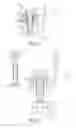
FIG. 1 is a cross-sectional view of an engine with a composite cover and a compression limiter/jack screw insert receiving a mounting screw according to the principles of the present disclosure;
FIG. 2 is a cross-sectional view of an engine with a composite cover and a compression limiter/jack screw insert receiving a jack screw according to the principles of the present disclosure;
FIG. 3 is a perspective view of a compression limiter/jack screw insert according to the principles of the present disclosure;
FIG. 4 is a cross-sectional view of an engine with a conventional composite cover and a compression limiter and separate jack screw insert with a mounting screw inserted through the compression limiter; and
FIG. 5 is a cross-sectional view of an engine with the conventional composite cover and a compression limiter and separate jack screw insert receiving a jack screw for removing the composite cover.
Corresponding reference numerals indicate corresponding parts throughout the several views of the drawings.
DETAILED DESCRIPTION
Example embodiments will now be described more fully with reference to the accompanying drawings.
Example embodiments are provided so that this disclosure will be thorough, and will fully convey the scope to those who are skilled in the art. Numerous specific details are set forth such as examples of specific components, devices, and methods, to provide a thorough understanding of embodiments of the present disclosure. It will be apparent to those skilled in the art that specific details need not be employed, that example embodiments may be embodied in many different forms and that neither should be construed to limit the scope of the disclosure. In some example embodiments, well-known processes, well-known device structures, and well-known technologies are not described in detail.
The terminology used herein is for the purpose of describing particular example embodiments only and is not intended to be limiting. As used herein, the singular forms “a,” “an,” and “the” may be intended to include the plural forms as well, unless the context clearly indicates otherwise. The terms “comprises,” “comprising,” “including,” and “having,” are inclusive and therefore specify the presence of stated features, integers, steps, operations, elements, and/or components, but do not preclude the presence or addition of one or more other features, integers, steps, operations, elements, components, and/or groups thereof. The method steps, processes, and operations described herein are not to be construed as necessarily requiring their performance in the particular order discussed or illustrated, unless specifically identified as an order of performance. It is also to be understood that additional or alternative steps may be employed.
When an element or layer is referred to as being “on,” “engaged to,” “connected to,” or “coupled to” another element or layer, it may be directly on, engaged, connected or coupled to the other element or layer, or intervening elements or layers may be present. In contrast, when an element is referred to as being “directly on,” “directly engaged to,” “directly connected to,” or “directly coupled to” another element or layer, there may be no intervening elements or layers present. Other words used to describe the relationship between elements should be interpreted in a like fashion (e.g., “between” versus “directly between,” “adjacent” versus “directly adjacent,” etc.). As used herein, the term “and/or” includes any and all combinations of one or more of the associated listed items.
With reference to FIGS. 1 and 2, an engine assembly 10 is shown including an engine structure 12 and a pan/cover assembly 14. The pan/cover assembly includes a composite body 16 having a mounting flange 18. A plurality of compression limiters 20 are mounted within the mounting flange 18 and in alignment with threaded mounting holes 22 in the engine structure 12. As shown in FIG. 1, mounting screw 24 is inserted through the compression limiter 20 and into the threaded mounting hole 22 for securing the pan/cover assembly 14 to the engine structure 12. A screw retainer 26, as is known in the art, can optionally be disposed within the compression limiter 20 and is capable of securing the mounting bolt 24 within the compression limiter 20 prior to assembly of the pan/cover assembly 10 to the engine structure 12.
The compression limiter 20 as shown in FIG. 3, includes a body 30 which can be made from a metallic material and has a predetermined thickness with an internally threaded aperture 32. The body 30 can include a polygonal exterior surface 34 with a plurality of flat surfaces and a radially outwardly extending flange portion 36. The compression limiter 20 can be press fit, bonded, overmolded or otherwise retained within a corresponding aperture in the mounting flange 18. The mounting bolt 24 has a bolt diameter that is smaller than an internal diameter of the internally threaded aperture 32 of the compression limiter 20.
As shown in FIG. 2, the mounting bolt 24 and optional screw retainer 26 can be removed from the threaded mounting hole 22 and compression limiter 20. A larger diameter jackscrew 40 can then be threadedly inserted into the internally threaded aperture 32 of the compression limiter 20 so that an end of the jackscrew 40 engages a surface of the engine structure 12 surrounding the threaded mounting hole 22 and causes a lifting of the compression limiter 20 and pan/cover assembly 14 away from the engine structure 12 in order to break the sealant bond between the pan/cover assembly 14 and engine structure 12.
The dual purpose threaded compression limiter 20 combines multiple functions into one component to be used in composite oil pan and cover assemblies. The compression limiter 20 improves serviceability of parts by allowing multiple pry points and reduces cost by eliminating separate threaded inserts. The compression limiters 20 improve component packaging around the sealing perimeter and of the boss around the engine structure. Although the dual purpose compression limiters 20 of the present disclosure have been disclosed in association with an engine assembly 10, it should be understood that the compression limiters 20 can be utilized on various oil pans and covers in engines, transmissions and other industrial machinery in which a composite material is utilized.
The foregoing description of the embodiments has been provided for purposes of illustration and description. It is not intended to be exhaustive or to limit the disclosure. Individual elements or features of a particular embodiment are generally not limited to that particular embodiment, but, where applicable, are interchangeable and can be used in a selected embodiment, even if not specifically shown or described. The same may also be varied in many ways. Such variations are not to be regarded as a departure from the disclosure, and all such modifications are intended to be included within the scope of the disclosure.
Claims
What is claimed is:1. An internal combustion engine, comprising:
an engine structure having a plurality of threaded bolt holes therein;
a cover mounted to the engine structure and made from a composite material, the cover including a flange portion having a plurality of compression limiters disposed therein, the compression limiters having an internal thread having a internal diameter larger than the threaded bolt holes in the engine structure; and
a plurality of mounting bolts extending through the compression limiters and threadedly engaged with the threaded bolt holes in the engine structure.
2. The internal combustion engine according to claim 1, further comprising bolt retainers received within the compression limiters between the mounting bolts and the compression limiters.
3. The internal combustion engine according to claim 1, wherein the cover is an oil pan.
4. The internal combustion engine according to claim 1, wherein the plurality of compression limiters are made from metal.
5. The internal combustion engine according to claim 1, wherein the plurality of compression limiters include a radially extending flange.
6. The internal combustion engine according to claim 1, wherein the plurality of compression limiters have a polygonal outer surface.
7. The internal combustion engine according to claim 1, further comprising a jack screw having a larger diameter than the plurality of mounting bolts and being threadedly received in the compression limiters for prying the cover away from the engine structure.
8. A method of removing a composite cover from an internal combustion engine including an engine structure having a plurality of threaded bolt holes, and a composite cover including a flange portion connected to the engine structure by a sealant and having a plurality of compression limiters disposed therein, the compression limiters having an internal thread having a pitch diameter larger than the threaded bolt holes, a plurality of mounting bolts extending through the compression limiters and threadably engaged with the threaded bolt holes in the engine structure, the method comprising:
removing the mounting bolts from the threaded bolt holes in the engine structure and threadably inserting a plurality of bolts into the internal thread of the compression limiters and against the engine structure surrounding the plurality of bolt holes to apply a separating force to the cover to overcome the sealant connection of the flange.
9. A cover member, comprising:
a body member made of a composite material and including a mounting flange; and
a plurality of compression limiters disposed in the mounting flange, the compression limiter having a predetermined thickness and an internally threaded aperture therein.
10. The cover member according to claim 1, wherein the cover is an oil pan.
11. The cover member according to claim 1, wherein the plurality of compression limiters are made from metal.
12. The cover member according to claim 1, wherein the plurality of compression limiters include a radially extending flange.
13. The cover member according to claim 1, wherein the plurality of compression limiters have a polygonal outer surface.
Images & Drawings included:


Sources:
- United States Patent and Trademark Office - verify current appl. status at the USPTO↗
Recent applications in this class:
- » 20250215918 2025-07-03
DEVICE FOR RETAINING A MOVING PART - » 20230044566 2023-02-09
RETAINING RING DEVICE - » 20220186766 2022-06-16
Spring-loaded locking bolt - » 20200224700 2020-07-16
Snap ring having retention feature - » 20180313387 2018-11-01
STRUCTURE AND METHOD FOR FIXING SEALING MATERIAL - » 20170292555 2017-10-12
Assembly unit - » 20170254351 2017-09-07
ANTI-ROTATION DEVICE AND ASSEMBLY - » 20160298669 2016-10-13
Fasteners and Other Assemblies - » 20140130316 2014-05-15
Fasteners and Other Assemblies - » 20140003865 2014-01-02
LOCKING APPARATUS
Recent applications for this Assignee:
- » 20250293679 2025-09-18
PROGNOSIS AND CONTROL OF POWER MODULE FOR ELECTRIC LOAD - » 20250293365 2025-09-18
FIBER-REINFORCED POLYMER BATTERY ENCLOSURES, COMPOSITE COMPONENTS, AND METHODS WITH INTEGRATED POLYMER SEALS - » 20250293279 2025-09-18
MEMBRANE ELECTRODE ASSEMBLY - » 20250293272 2025-09-18
METAL BEAD SEAL BUCKLING LOAD AND PRESSURE UNIFORMITY WITH AN ENFORCEMENT LAYER - » 20250293270 2025-09-18
METHOD OF SHAPING BIPOLAR PLATES - » 20250289417 2025-09-18
DETERMINATION OF EVASIVE MANEUVER ACTION TO AVOID ONCOMING ROAD HAZARD OF A VEHICLE - » 20250289366 2025-09-18
SYSTEM AND METHOD FOR NOTIFYING PASSENGERS OF NEARBY OBJECTS - » 20250286485 2025-09-11
CONTROL CIRCUIT FOR A DIRECT CURRENT MOTOR - » 20250286331 2025-09-11
ELECTRICAL CONNECTOR MOUNTING - » 20250286096 2025-09-11
MEMBRANE ELECTRODE ASSEMBLY HAVING AN ORGANIC SOLVENT