Bleacher umbrella caddy
US20190048610A1
2019-02-14
15/673,718
2017-08-10
✅ Patent granted
US 10,597,891 B2
2020-03-24
-
-
Terrell L McKinnon | Michael McDuffie
Van R. Irion
2037-08-10
Abstract:
An umbrella holder holds an umbrella and attaches to sports bleachers. Holder includes a hollow tube for placing an umbrella handle and a threaded rod screwed in the tube for tightening or releasing the umbrella handle. An attaching mechanism is fixed to the hollow tube and includes a means for clamping holder to sports bleachers.
Inventors:
- Rudy Preciado 1 🇺🇸 Lenoir City, TN, United States
- Renee Preciado 1 🇺🇸 Lenoir City, TN, United States
Applicant:
Interested in similar patents?
Get notified when new applications in this technology area are published.
Classification:
E04H12/2269 » CPC main
Towers; Masts or poles; Chimney stacks; Water-towers; Methods of erecting such structures; Sockets or holders for poles or posts; Mounting poles or posts to the holder in a socket
F16M13/022 » CPC further
Other supports for positioning apparatus or articles ; Means for steadying hand-held apparatus or articles for supporting on, or attaching to, an object, e.g. tree, gate, window-frame, cycle repositionable
E04H12/22 IPC
Towers; Masts or poles; Chimney stacks; Water-towers; Methods of erecting such structures Sockets or holders for poles or posts
F16M13/02 IPC
Other supports for positioning apparatus or articles ; Means for steadying hand-held apparatus or articles for supporting on, or attaching to, an object, e.g. tree, gate, window-frame, cycle
Description
This is a Non-Provisional patent application filed for the invention by Rudy Preciado and Renee Preciado of 3807 Town Creek Road West, Lenoir City, Tenn. 37771, for new and useful “Bleacher Umbrella Caddy.”
FIELD OF THE INVENTION
The invention relates to an umbrella holder; and more particularly to a portable umbrella holder having features allowing quick, easy, and secure temporary attachment to bleachers and other common outdoor structures.
BACKGROUND OF THE INVENTION
It is often desirable to have an umbrella to provide a welcome shield from the sun or rain. The use of umbrellas during the viewing of various sporting events has been widely practiced during both rain periods as well as sun periods. The umbrella protects the sports fan from the heat of the sun and also protects the fan as well as his personal items from the rain.
However, manually holding an umbrella can prove quite cumbersome. Furthermore, holding an umbrella for an entire sporting event will prove tiring. It would be a benefit, therefore, to have an umbrella holder that could be affixed to the handle of an existing umbrella and could be secured to a fixed object, and be positioned at a desired height to afford a user protection from the weather. It would be further desirable if the umbrella holder were lightweight and securable to a variety of structures, including bleachers commonly found at sporting events.
To solve these problems, umbrella holders have been developed in the art. Such devices relieve the sports fan from manually holding the umbrella by attaching the umbrella to various fixed objects, such as folding chairs, picnic tables, golf bags, ice chests, and similar objects. However, the prior art devices are either too complex to build or use or require a permanent alteration to the object to which it is attached.
Therefore, there is a need in the art for a portable umbrella holder that quickly, easily, and temporarily attaches to a fixed object without modifying or damaging the fixed object.
SUMMARY OF THE INVENTION
The umbrella holder of the present invention addresses the aforementioned needs in the art. The umbrella holder quickly and easily attaches to and detaches from bleachers without the need to modify the bleachers or the umbrella. The umbrella holder is of relatively simple design and construction.
The umbrella holder comprises a tube; a first L-bracket; a second L-bracket; a clamp mechanism; and an umbrella shaft and handle-securing mechanism.
The first and second L-brackets each have a ninety degree bend at their mid-points. The second L-bracket, in the same orientation as the first, attaches to the first L-bracket flush along a first side of both L-brackets. Attachment leaves a gap between a second side of the L-brackets, said second side of the L-brackets are disposed generally parallel to each other. A first clamping mechanism is attached to the first L-bracket at the second side, oriented to clamp objects between the first and second L-brackets. A tube is attached to first and second L-brackets at the first side of said L-brackets, along the flat side of the L-brackets. The tube is oriented such that one end points up when the umbrella holder is attached to a bleacher seat.
In the preferred embodiment the L-brackets consist of steel.
In an alternative embodiment the first L-bracket is shorter on the first side, thereby leaving the top ends of the first and second L-brackets flush with each other.
In the preferred embodiment the umbrella holder includes an umbrella shaft securing mechanism comprising a second clamping mechanism attached to the tube. The second clamping mechanism holds an umbrella handle and shaft after the umbrella handle and shaft are inserted into the tube. The second clamping mechanism also allows the user to raise and lower the umbrella relative to the tube.
In the preferred embodiment the first clamping mechanism is comprised of a first and second screw mechanism threaded through the second side of the first L-bracket. The screw mechanisms are oriented such that one end of the screw mechanisms extends down from the first L-bracket toward the second L-bracket when the screw mechanism is turned, thereby impinging upon the top of a bleachers seat or other structure that has been inserted between the first and second L-brackets. The impingement of the screw mechanism upon the bleachers seat causes the second L-bracket to impinge upon the bottom of the bleachers seat, thereby mechanically securing the umbrella holder to the bleachers seat.
In the preferred embodiment one end of the screw mechanisms include a knob configured to aid in manual turning of the screw mechanisms.
In an alternate embodiment the screw mechanisms are wing screws.
In an alternate embodiment an appropriate non-scuff material such as rubber or neoprene can be secured to the surfaces of the L-brackets and the impinging end of the screw mechanisms in order to prevent damage to the bleachers seat and to increase the coefficient of friction between the umbrella holder and the bleachers seat or other structure.
In the preferred embodiment the second clamping mechanism is a third screw mechanism threaded through the side of the tube. After an umbrella handle or shaft are inserted into the top of the tube, the screw mechanism is turned causing one end of the screw mechanism to extend into the interior of the tube, thereby impinging upon the umbrella handle or shaft. The second clamping mechanism allows the user to adjust the length of the umbrella protruding from the tube, while simultaneously preventing the umbrella from being blown out of the tube.
In an alternate embodiment an appropriate non-scuff material such as rubber or neoprene can be secured to the interior surfaces of the tube and the impinging end of the screw mechanism in order to prevent damage to the umbrella and to increase the coefficient of friction between the umbrella holder and the umbrella.
In another alternate embodiment the first clamping mechanism is attached to the second side of the second L-bracket, thereby having a means of tightening the clamp on the bottom of the device, to impinge upon the bleachers seat from below.
It is thus an objective of the invention to provide an umbrella holder that is securable to the shaft and handle of an existing umbrella that includes a mechanism for securing the umbrella holder to a variety of support structures and that is provided with positioning mechanisms to allow the user to position the umbrella at a desired height.
It is another objective of this invention is to offer an umbrella holder that is quick in its attachment and detachment to a bleachers seat and similar structures, and is thereby convenient in operation.
It is a still further objective of the invention to provide an umbrella holder that includes an umbrella shaft and handle securing mechanism that can be used to secure a variety of umbrella shaft and handle configurations to the umbrella holder.
It is a still further objective of the invention to provide an umbrella holder that accomplishes all or some of the above objects in combination.
It is to be understood that both the foregoing general description and the following detailed description provide embodiments of the invention and are intended to provide an overview or framework of understanding the nature and character of the invention as it is claimed.
BRIEF DESCRIPTION OF THE DRAWINGS
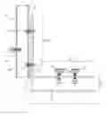
FIG. 1 is a side view with cutaway of the tube of an embodiment of the umbrella holder.
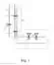
FIG. 2 is a top view of the embodiment disclosed in FIG. 1.
FIG. 3 is a side view of the embodiment disclosed in FIG. 1.
Before explaining the disclosed embodiment of the present invention in detail, it is to be understood that the invention is not limited in its application to the details of the particular arrangement shown, since the invention is capable of other embodiments. Also, the terminology used herein is for the purpose of description and not of limitation.
DETAILED DESCRIPTION OF THE PREFERRED EMBODIMENT
The present invention, which is described more fully hereinafter, provides an umbrella holder that quickly and easily attaches to and detaches from bleachers without the need to modify the bleachers or the umbrella. This invention may be embodied in many different forms and should not be construed as limited to the specific embodiments described herein.
Referring now to FIG. 1 the preferred embodiment of the umbrella holder includes a first L-bracket [1] having a ninety degree bend [2] at its midpoint. A second L-bracket [3] is essentially identical to the first L-bracket [1]. The first and second L-brackets are attached at a first side [4] and [5] of each L-bracket. The L-brackets are in the same orientation to each other and are attached such that the second side [6] of the first L-bracket [1] is separated from the second side [7] of the second L-bracket [3], thereby creating a gap [8]. A tube [9] is attached to the first side [4] of the first L-bracket [1] and the first side [5] of the second L-bracket [3]. The attachment is made via use of a first bolt [10] inserted through the first [1] and second [3] L-brackets and the tube [9], and a second bolt [11] inserted through the first [1] and second [3] L-brackets and the tube [9] at a point below the first bolt [10]. Both bolts are secured with a nut [12],[13]. Two clamping screws [14],[15] are threaded through the second side [4] of the first L-bracket [1]. The clamping screws can be lowered to impinge upon a bleachers seat by turning knobs [16],[17] attached to the clamping screws [14],[15]. A third clamping screw [18] is threaded through the side of the tube [9] to allow securing of an umbrella shaft or handle inside the tube [9].
Referring now to FIG. 2, the first L-bracket [19] of FIG. 2 corresponds to the first L-bracket [1] in FIG. 1. The second L-bracket [20] corresponds to the second L-bracket [3] of FIG. 1. The bend [21] corresponds to the bend [2] in FIG. 1. The first side [22] and [23] of each L-bracket [19],[20] corresponds to the first side of each L-bracket [1],[3] in FIG. 1. The second side [24] of the first L-bracket [19] corresponds to the second side [6] of the first L-bracket in FIG. 1. The second side of the second L-bracket, as well as the gap, cannot be seen from the top view. The tube [25] corresponds to the tube [9] in FIG. 1. The first bolt [26] corresponds to the first bolt [10] in FIG. 1. The second bolt cannot be seen from the top view. The nut [26] corresponds with the nut [12] in FIG. 1. In an alternative embodiment the first and second nut and bolt assembly are oriented 180 degrees from the orientation represented in the Figures, thereby reducing protrusion of the bolt into the interior of the tube. The knobs [27],[28] correspond to the knobs [16],[17] in FIG. 1. The third clamping screw [29] corresponds to the third clamping screw [18] in FIG. 1.
Referring now to FIG. 3, the first L-bracket [30] corresponds to the first L-bracket [1],[19] in FIG. 1 and FIG. 2, respectively. The second L-bracket [31] corresponds to the second L-bracket [3],[20] of FIG. 1 and FIG. 2, respectively. The bend [32] corresponds to the bend [2],[21] in FIG. 1 and FIG. 2, respectively. The first side [33] and [34] of each L-bracket [30],[31] corresponds to the first side of each L-bracket [1],[3],[22],[23] in FIG. 1 and FIG. 2, respectively. The second side [35] of the first L-bracket [30] corresponds to the second side [6],[24] of the first L-bracket [30] in FIG. 1 and FIG. 2, respectively. The second side [36] of the second L-bracket [31] corresponds to the second side [7] of the second L-bracket [31] in FIG. 1 The tube [37] corresponds to the tube [9],[25] in FIG. 1 and FIG. 2, respectively. The first bolt [38] corresponds to the first bolt [10],[26] in FIG. 1 and FIG. 2, respectively. The nut [39] corresponds with the nut [12] in FIG. 1. The knobs [40],[41] correspond to the knobs [16],[17] in FIG. 1 and [27],[28] in FIG. 2. The third clamping screw [42] corresponds to the third clamping screw [18],[29] in FIG. 1 and FIG. 2, respectively.
EXAMPLE
The invention is further described by the following non-limiting example of use.
The user slides the umbrella holder over the bleachers seat such that the gap of the umbrella holder is filled by the bleachers seat, leaving the bleachers seat between the second side of the first L-bracket and the second side of the second L-bracket. The user then engages the first clamping mechanism by turning the knobs on the first and second screwing mechanism. This causes one end of the screwing mechanism to impinge upon the top of the bleachers seat, causing the second side of the second L-bracket to rise and impinge upon the bottom of the bleachers seat. The user then inserts an umbrella handle or shaft into the tube. The user then secures the umbrella handle or shaft by turning the third knob causing the second clamping mechanism to impinge upon the umbrella shaft within the tube.
Claims
1: An umbrella holder, consisting of:
A first L-bracket, said L-bracket having a ninety degree bend at the mid-point, said L-bracket further having a first side and a second side,
a second L-bracket, said L-bracket having a ninety degree bend at the mid-point, said L-bracket further having a first side and a second side; said second L-bracket in the same orientation as the first L-bracket, said first side of said second L-bracket affixed to said first side of said first L-bracket;
a gap between said second side of said first L-bracket and said second side of said second L-bracket, said gap being the space between second side of said first and second L-brackets which are disposed generally parallel to each other;
a first clamping mechanism affixed to the first L-bracket at the second side, oriented to clamp objects between the first and second L-brackets, said first clamping mechanism consisting of a first screw mechanism and second screw mechanism, said screw mechanisms threaded through the first side of the first L-bracket, said screw mechanisms oriented such that one end of said screw mechanisms extend down from the first L-bracket toward the second L-bracket when the screw mechanism is turned, thereby impinging upon the top of a horizontal surface said horizontal surface having been inserted into said gap, said second side of said first L-bracket and said second side of said second L-bracket oriented horizontally above and below said bleachers seat;
a means to manually turn said first screw mechanism;
a means to manually turn said second screw mechanism;
a tube affixed to said first L-bracket and said second L-bracket at said first side of said L-brackets, said tube oriented such that one end points up when said umbrella holder is attached to said bleacher seat;
a mechanism for securing an umbrella shaft, comprising a second clamping mechanism attached to said tube, said second clamping mechanism consisting of a third screw mechanism, said screw mechanism threaded through the side of said tube, oriented such that one end of said screw mechanism extends into the interior of said tube toward an umbrella shaft when the screw mechanism is turned, thereby impinging upon the side of said umbrella shaft and securing said umbrella shaft against an interior side of said tube;
a first non-scuff material secured to a first surface of said second side of said first L-bracket;
a second non-scuff material secured to a second surface of said second side of said second L-bracket;
a third non-scuff material secured to said first screw mechanism;
a fourth non-scuff material secured to said second screw mechanism;
a fifth non-scuff material secured to said third first screw mechanism; and
a sixth non-scuff material secured to interior of said tube.
2: The umbrella holder of claim 1 wherein said means to manually turn said first screw is a knob.
3: The umbrella holder of claim 1 wherein said means to manually turn said first screw is a wing screw.
4: The umbrella holder of claim 1 wherein said non-scuff material is rubber.
5: The umbrella holder of claim 1 wherein said non-scuff material is neoprene.
6: A umbrella holder comprising:
A first L-bracket, said L-bracket having a ninety degree bend at the mid-point, said L-bracket further having a first side and a second side,
a second L-bracket, said L-bracket having a ninety degree bend at the mid-point, said L-bracket further having a first side and a second side; said second L-bracket in the same orientation as the first L-bracket, said first side of said second L-bracket affixed to said first side of said first L-bracket;
a gap between said second side of said first L-bracket and said second side of said second L-bracket, said gap being the space between second side of said first and second L-brackets which are disposed generally parallel to each other;
a first clamping mechanism affixed to the first L-bracket at the second side, oriented to clamp objects between the first and second L-brackets, said first clamping mechanism consisting of a first screw mechanism and second screw mechanism, said screw mechanisms threaded through the first side of the first L-bracket, said screw mechanisms oriented such that one end of said screw mechanisms extend down from the first L-bracket toward the second L-bracket when the screw mechanism is turned, thereby impinging upon the top of a bleachers seat said bleachers seat having been inserted into said gap, said second side of said first L-bracket and said second side of said second L-bracket oriented horizontally above and below said bleachers seat;
a means to manually turn said first screw mechanism;
a means to manually turn said second screw mechanism;
a tube affixed to said first L-bracket and said second L-bracket at said first side of said L-brackets, said tube oriented such that one end points up when said umbrella holder is attached to said bleacher seat;
a mechanism for securing an umbrella shaft, comprising a second clamping mechanism attached to said tube, said second clamping mechanism consisting of a third screw mechanism, said screw mechanism threaded through the side of said tube, oriented such that one end of said screw mechanism extends into the interior of said tube toward an umbrella shaft when the screw mechanism is turned, thereby impinging upon the side of said umbrella shaft and securing said umbrella shaft against an interior side of said tube;
a first non-scuff material secured to a first surface of said second side of said second L-bracket;
a second non-scuff material secured to a second surface of said second side of said second L-bracket;
a third non-scuff material secured to said first screw mechanism;
a fourth non-scuff material secured to said second screw mechanism;
a fifth non-scuff material secured to said third first screw mechanism; and
a sixth non-scuff material secured to interior of said tube.
7: The umbrella holder of claim 6 wherein said means to manually turn said first screw is a knob.
8: The umbrella holder of claim 6 wherein said means to manually turn said first screw is a wing screw.
9: The umbrella holder of claim 6 wherein said non-scuff material is rubber.
10: The umbrella holder of claim 6 wherein said non-scuff material is neoprene.
11: (canceled)
12: An umbrella holder, comprising:
a tube;
a first L-bracket;
a second L-bracket; said tube affixed to said first L-bracket;
a clamp mechanism affixed to said first L-bracket;
a bleacher seat; said bleacher seat clamped to said first L-bracket.
13: The umbrella holder of claim 12 further comprising a second clamp mechanism affixed to said tube.
14: The umbrella holder of claim 12 further comprising a gap between a second side of said first L-bracket and a second side of said second L-bracket.
15: The umbrella holder of claim 12 wherein said L-brackets consist of steel.
16: The umbrella holder of claim 12 further comprising a first strip of non-scuff material affixed to a second side of said first L-bracket and a second side of said second L-bracket.
17: The umbrella holder of claim 12 wherein said clamp mechanism comprises a screw.
Images & Drawings included:


Sources:
- United States Patent and Trademark Office - verify current appl. status at the USPTO↗
Recent applications in this class:
- » 20250283344 2025-09-11
POLE ASSEMBLY - » 20250101764 2025-03-27
OUTDOOR CENTER POLE STRUCTURE - » 20250067078 2025-02-27
UMBRELLA HOLDING DEVICE - » 20250067077 2025-02-27
APPARATUS FOR SECURING POLE - » 20250003247 2025-01-02
POST SOCKET - » 20240352760 2024-10-24
POST ANCHOR - » 20240352759 2024-10-24
POLE INSTALLATION METHOD - » 20240151059 2024-05-09
POST ANCHOR - » 20240060325 2024-02-22
CENTER POLE FIXING STRUCTURE - » 20240052666 2024-02-15
Umbrella Mount