FAN AND FAN BLADE
US20190242398A1
2019-08-08
16/155,579
2018-10-09
Abstract:
A ceiling fan is disclosed comprising a plurality of fan blades, the plurality of fan blades including a main fan blade portion and an upwardly extending vertical blade portion whereby the ceiling fan blades will direct the air flow both vertically and horizontally.
Assignee:
- Ventura Innovations LLC 1 🇺🇸 Bryn Mawr, PA, United States
Interested in similar patents?
Get notified when new applications in this technology area are published.
Classification:
F04D29/384 » CPC main
Details, component parts, or accessories; Rotors specially for elastic fluids for axial flow pumps; Blades characterised by form
F04D25/088 » CPC further
Pumping installations or systems; Units comprising pumps and their driving means the working fluid being air, e.g. for ventilation Ceiling fans
F04D29/38 IPC
Details, component parts, or accessories; Rotors specially for elastic fluids for axial flow pumps Blades
F04D25/08 IPC
Pumping installations or systems; Units comprising pumps and their driving means the working fluid being air, e.g. for ventilation
Description
RELATED APPLICATION
This application claims benefit of U.S. Provisional Application Ser. No. 62/625,563, filed Feb. 2, 2018, entitled “Fan and Fan Blade,” which application is incorporated herein by reference in its entirety.
FIELD OF THE INVENTION
The present invention relates to a ceiling fan. More particularly, the invention relates to a ceiling fan having fan blades providing for circulation of the air both horizontally and vertically.
BACKGROUND OF THE INVENTION
Ceiling fans are known in the art. The most common complaint about such ceiling fans is that they drive an airstream of air directly onto the person or persons below such fans. This often creates discomfort and requires the user to make frequent adjustments to the fan speed or even shutting the fan down completely.
Accordingly, the present ceiling fans have various shortcomings including not only directing the air flow vertically but also not directing the air flow throughout a room. These and other shortcomings of known ceiling fans are addressed by the present invention.
SUMMARY OF THE INVENTION
A primary object of the present invention is to provide an improved ceiling fan which will direct the air flow both horizontally and vertically.
Another primary object of the present invention is to provide a ceiling fan blade attachment for retrofitting to existing ceiling fans to provide for horizontal air flow from the ceiling fan.
Another primary object of the present invention is to provide for a ceiling fan having fan blades which will provide air flow both vertically and horizontally.
Another primary object of the present invention is to provide a ceiling fan having fan blades comprising a vertical blade atop a main fan blade to provide horizontal air flow. Such vertical blade may be retrofitted on an existing ceiling fan blade, or sold with a ceiling fan as an attachment to the main blade, or made as an integral unit with the main blade.
Another primary object of the present invention is to provide a ceiling fan with fan blades having a vertical blade which may be attached to a main fan blade by various means including friction fit, glue, screws, welding or other methods for producing a junction that will not be impaired by the rotation of the main fan blade under motor propulsion. The vertical blades are attached to each of the main blades at the same location.
Another primary object of the present invention is to provide for a ceiling fan with fan blades whereby a vertical portion of the fan blade may be formed by bending the trailing edge of a main blade portion upward to form an upright segment, the surface of which may be either flat or curved.
Another primary object of the present invention is to provide a ceiling fan with fan blades wherein the fan blades include a vertical member and such vertical member may rest flush on the top side of a main fan blade to avoid small openings which may create drag upon the blade rotation and/or noise of the moving air.
Another primary object of the present invention is to provide for a ceiling fan having fan blades having a vertical portion which may be attached to a main blade portion with hinges or other adjustable device such that the angle of the vertical portion of the fan blade may be adjusted to produce greater or lesser horizontal air flow.
Another primary object of the present invention is to provide for a ceiling fan having fan blades having a vertical portion which may be designed with a portion of it aimed upward so as to direct some of the airflow at the ceiling.
The present invention comprises a ceiling fan having a plurality of fan blades, the plurality of fan blades including a main fan blade portion having an upwardly extending vertical portion whereby the ceiling fan blades will direct the air flow both vertically and horizontally. The vertical portion of the fan blade may be attachable to the main blade portion of the ceiling fan or may be made integral with the ceiling fan blades.
These primary and other objects of the invention will be apparent from the following description of the preferred embodiments of the invention and from the accompanying drawings.
BRIEF DESCRIPTION OF THE DRAWINGS
The following detailed description of the specific non-limiting embodiments of the present invention can be best understood when read in conjunction with the following drawings, where like structures are indicated by like reference numbers.
Referring to the drawings:
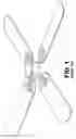
FIG. 1 shows a prior art ceiling fan.
FIG. 2 shows a ceiling fan having vertical fan blade portions attached to ceiling fan blades to provide both horizontal and vertical air flow.
FIG. 3 shows a bottom perspective view of the ceiling fan of FIG. 2.
FIG. 4 shows a ceiling fan blade of the ceiling fan of FIG. 2.
FIG. 5 shows a perspective view of the vertical blade portion of the ceiling fan blades shown in FIG. 2.
FIG. 6 shows a front view of the vertical portion of FIG. 5.
FIG. 7 shows a cross-section of the vertical blade portion taken along line 7-7 of FIG. 6.
FIG. 8 shows a ceiling fan having a main blade portions and vertical blade portions wherein the vertical portion is integral with the main blade portion.
FIG. 9A shows an alternative embodiment of a ceiling fan blade having a main blade portion and a vertical blade portion.
FIGS. 9B and 9C show the vertical blade portion of the ceiling fan blade of FIG. 9A.
FIG. 9D shows the main blade portion of the ceiling fan blade of FIG. 9A with dimensions.
FIGS. 9E and 9F show vertical blade portion of the ceiling fan blade of FIG. 9A with dimensions.
FIG. 10 shows a ceiling fan using the fan blades of FIG. 9A.
DETAILED DESCRIPTION OF THE PREFERRED EMBODIMENTS
The present invention is directed to a ceiling fan and a ceiling fan blade which will provide both horizontal and vertical air flow. This will resolve the discomfort of the prior art ceiling fans such as shown in FIG. 1 which direct all of the air vertically onto persons in the room and do not provide horizontal air flow. The present invention includes a main fan blade portion and a vertical fan blade portion. The vertical portion may be a separate element such as shown in FIGS. 2-7 and 9-10 and made to retrofit existing ceiling fans or sold as a part of a new ceiling fan. In the alternative, as shown in FIG. 8, the ceiling fan with the ceiling fan blades may be manufactured and sold with the vertical portion being integral with the main blade portion.
Referring to FIGS. 2-7, the invention will first be described wherein the vertical portion of the fan blade is attachable to the main blade portion. Referring to FIG. 2, there is shown a ceiling fan 10 having a plurality of blades 12 generally in a horizontal plane and referred to as the main blade portion. It is understood that ceiling fan 10 includes a motor for rotating the fan blades and which is not shown. The motor may rotate the fan blades at different speeds of rotation. Fan blades 12 are as known in the art and may be of various sizes and shapes. Fan blades 12 are generally parallel to the floor below the ceiling fan. There is a vertical portion 14 atop blades 12. Vertical portion 14 rises from the near trailing edge of the blade 12 and is substantially perpendicular to the floor below the ceiling fan. In one preferred embodiment, the vertical portion may be C-shaped, but the invention is not limited thereto. The blade portion 12 functions to direct air downward from the fan's hub H. The vertical blade portion 14 directs air outward from the fan's hub H. The amount of air directed downward or outward is a function of the relative size and shape of the blade portions 12 and 14. Many different blade sizes and shapes may be combined in order to produce both horizontal and vertical airstreams of varying strength. This makes it possible to design blade configurations to move air out to the perimeter of different size rooms.
A presently preferred embodiment of fan blade portions 12 and 14 may comprise a vertical portion 14 which is at least forty percent as long as the main blade portion 12.
The vertical blade portion 14 may be attached to the main blade portion 12 by friction fit, gluing, screws, welding or any other method producing a junction that will not be impaired by the rotation of the main blade portion under motor propulsion. The vertical blade 14 should be attached to main blade portion 12 in the same location, for example, as shown in FIGS. 2 and 3. Referring to FIGS. 2-7, one preferred method of attaching vertical blade portion 14 is through a tongue and groove mechanism where the trailing edge of main blade portion 12 includes a portion 20 which functions as the tongue and vertical blade portion 14 includes a groove 22. Vertical blade portion 14 is attached at groove 22 to main blade portion 20 by friction fit.
As stated above, other means may be used for attaching vertical blade portion 14 to main blade portion 12. Referring to FIGS. 9A-9F, there is shown an alternative means of attaching vertical blade portion 14A to main blade portion 12. In this embodiment, vertical blade portion 14A includes an L-shaped member 24 which may be attached to the underside of main blade 12 by an adhesive. In the alternative, screws or other attachment means may be used to attach L-shaped member 24 to main blade portion 12. In the alternative and referring to FIG. 10, L-shaped member 24 may be attached to the top of main blade portion 12. As an example only, FIGS. 9A and 9D-9F disclose preferred dimensions of the main blade portion 12 and the vertical blade portion 14A.
Referring to FIG. 8, a vertical blade portion 14B may be formed by bending the trailing edge of the main blade 12 upward to form an upright segment. In this embodiment, the main blade portion 12B and vertical blade portion 14B are integral and formed as a single blade by, for example, injection molding. In this embodiment, the blade may be made of a moldable material such as plastic.
In the alternative, the vertical blade portion 14 may be attached to main blade portion 12 with hinges or other adjustable device such that the angle of the vertical blade portion may be adjusted to produce greater or lesser horizontal air flow. Additionally, the vertical blade portion 14 may be designed with a portion of it aimed upward (not shown) so as to direct some of the air at the ceiling.
In order to determine the usefulness of the present invention, a full size model of the invention with a vertical blade portion 14 as seen in FIG. 10 was tested. A lit cigarette lighter was held below the fan and, while the flame flickered, it was not extinguished. When the same cigarette lighter flame was moved upward and along side the fan, it was almost immediately blown out by the horizontal movement of the air.
In a further test to determine the usefulness of the invention and to confirm the air flow of the ceiling fan of the invention, a ceiling fan as shown in FIG. 10 was installed in the middle of a ceiling of an interior room without windows. Each fan blade was as shown in FIG. 10, having a main fan blade portion 12 and a smaller vertical blade portion 14A mounted on the trailing edge of the main fan blade portion 12. As the fan rotates, the horizontal fan blades 12 push air upward and the vertical blades 14A push air outward. To determine where the air is moving, colored paper streamers were hung from the ceiling around the perimeter of the room. A long paper streamer was hung from the center of the fan motor and a plastic plant having leaves was placed on a table below the fan, both directly in the path of downward flowing air. The ceiling fan was turned on and the effect of the main blade portion and the vertical blade portion was seen by observing the streamers. The streamers around the perimeter of the room continually danced as the air moved past them and down the walls. At the same time, the long streamer directly under the fan hardly moved at all. And the leaves of the plant on the table below the fan barely moved at all. The air stream resulting from adding the vertical blade portion is analogous to a wide umbrella with only a minimum amount of air dropping directly downward. Thereafter, the vertical blade portions 14A were removed from the main blade portions 12 and the fan, now a traditional fan with one-plane fan blades was tested in the same room and at the same fan rotation speed. The streamers directly below the fan moved actively from side to side. Also, the leaves of the plant on the table swayed in response to the downward air stream. The streamers hanging around the periphery of the room were pulled inward toward the downward air stream under the fan. In sum, the air stream from a traditional ceiling fan may be visualized as a cone shape, narrow at the top, widening as the air falls. The air stream from the invention rises from the fan and rapidly widens until gravity or an obstacle causes the air to fall.
The exemplary embodiments herein disclosed are not intended to be exhaustive or to unnecessarily limit the scope of the invention. The exemplary embodiments were chosen and described in order to explain the principles of the present invention so that others skilled in the art may practice the invention. As will be apparent to one skilled in the art, various modifications can be made within the scope of the aforesaid description. Such modifications being within the ability of one skilled in the art form a part of the present invention and are embraced by any appended claims.
Claims
It is claimed:1. A ceiling fan comprising a plurality of fan blades, each of said plurality of fan blades including a main fan blade portion in a horizontal plane and an upwardly extending vertical blade portion in a vertical plane, whereby the plurality of fan blades will direct the air flow from said fan both vertically and horizontally.
2. The ceiling fan according to claim 1 wherein the vertical blade portion is connectively attached to the main blade portion.
3. The ceiling fan according to claim 2 wherein the vertical blade portion is attached to the main blade portion by friction fit, screws, glue or welding.
4. The ceiling fan according to claim 1 wherein the vertical blade portion is integral to the main blade portion.
5. The ceiling fan according to claim 1 wherein the vertical blade portion is C-shaped.
6. A fan blade attachment for a ceiling fan blade which is adapted to be in a horizontal plane in relation to a ceiling comprising an attachment member adapted to attach to said ceiling fan blade and extend upwardly from said ceiling fan blade and in a plane vertical to said ceiling.
7. The fan blade attachment according to claim 6 wherein the vertical blade portion is adapted to be connectively attached to the main blade portion.
8. The fan blade attachment according to claim 7 wherein the vertical blade portion is adapted to be attached to the main blade portion by friction fit, screws, glue or welding.
9. The fan blade attachment according to claim 6 wherein the vertical blade portion is C-shaped.
Images & Drawings included:


Sources:
- United States Patent and Trademark Office - verify current appl. status at the USPTO↗
Similar patent applications:
- » 20130272862
METHOD FOR MANUFACTURING FAN BLADE AND FAN USING SUCH FAN BLADES - » 20170023009
Fan blade with segmented fan blade cover - » 20190308376
Method of manufacturing a fan blade and a fan blade - » 20200024958
Method of manufacturing a fan blade and a fan blade - » 20150211371
METHOD FOR MANUFACTURING CEILING FAN BLADE AND CEILING FAN BLADE - » 20160169244
METHOD FOR MANUFACTURING CEILING FAN BLADE AND CEILING FAN BLADE - » 20170023007
Fan blade with integrated composite fan blade cover - » 20210062818
Fan blade support assembly for fan blade, air duct assembly and air conditioner - » 20090123286
Assembly of a fan blade and of its damper, fan blade damper and method for calibrating the damper - » 20170282466
Fan blade and method of manufacturing a fan blade
Recent applications in this class:
- » 20250172158 2025-05-29
BLADE FOR AN INDUSTRIAL AXIAL FAN WITH TIP LIFT APPENDAGE - » 20250067277 2025-02-27
INDUSTRIAL AXIAL FAN BLADE - » 20250020140 2025-01-16
COMBINED FAN BLADE STRUCTURE AND AIR OUTLET DEVICE - » 20250003421 2025-01-02
AIR HANDLING UNIT WITH DIAGONAL FLOW FAN - » 20250003420 2025-01-02
Propeller fan, blower, and air conditioner - » 20240426316 2024-12-26
TURBOMACHINE AND METHOD OF ASSEMBLY - » 20240426315 2024-12-26
BLOWER WITH TOROIDAL FAN BLADES - » 20240418182 2024-12-19
TURBOMACHINE AND METHOD OF ASSEMBLY - » 20240418181 2024-12-19
TURBOMACHINE AND METHOD OF ASSEMBLY - » 20240418180 2024-12-19
TURBOMACHINE AND METHOD OF ASSEMBLY