DEVICE FOR AIRING OUT BLANKETS AND THE LIKE
US20190274440A1
2019-09-12
16/348,880
2017-11-23
Abstract:
Device for airing blankets comprising a crosspiece connected to a bed frame, at least two tubular profiles connected to each which can pivot. A spring element arranged inside each tubular profile passing through at least one second tubular profile for one first pipe profile and connects the second pipe profile to a first pipe profile wherein the second pipe profiles are connected to a support surface for a blanket and can be pivoted about an axis perpendicular to a support surface. An element is fastened to the first or second tubular profiles forming a receptacle for the pipe profile to be fastened, which fastens the first tubular profiles to the second tubular profiles. The first tubular profiles are arranged laterally in contact with each other and the second tubular profiles contact each other laterally wherein the first tubular profiles are vertically aligned with the respective second tubular profiles.
Assignee:
- TECNOSERVICE KG/SAS D. WEGLEITER H. & CO. 1 🇮🇹 Lana, Italy
Interested in similar patents?
Get notified when new applications in this technology area are published.
Classification:
A47C21/022 » CPC main
Attachments for beds, e.g. sheet holders, bed-cover holders ; Ventilating, cooling or heating means in connection with bedsteads or mattresses sheet holders Holders for loose bed elements, e.g. ; bed cover holders Sheet holders; Bed cover holders
A47C21/046 » CPC further
Attachments for beds, e.g. sheet holders, bed-cover holders ; Ventilating, cooling or heating means in connection with bedsteads or mattresses; Devices for ventilating, cooling or heating for ventilating or cooling without active means, e.g. with openings or heat conductors
A47C21/02 IPC
Attachments for beds, e.g. sheet holders, bed-cover holders ; Ventilating, cooling or heating means in connection with bedsteads or mattresses sheet holders Holders for loose bed elements, e.g. ; bed cover holders
A47C21/04 IPC
Attachments for beds, e.g. sheet holders, bed-cover holders ; Ventilating, cooling or heating means in connection with bedsteads or mattresses Devices for ventilating, cooling or heating
Description
BACKGROUND OF THE INVENTION
The invention relates to a device for airing out blankets and the like.
A multitude of blanket stands are known in AT 004 115 U1 which discloses a device for airing out a blanket. The device as disclosed in AT 004 115 U1 comprises a pantograph or telescopic-rod structure which is deployed and locked by means of spring-loaded pins.
The structure as disclosed in AT 004 115 U1 has large space requirements and is not stable after assembly.
US 2007126317 A1 discloses a support device for clothes and the like. This device consists of a rectangular structure composed of rods for fixation of clothes or the like. The structure takes up a large space and its individual parts must be assembled each time to form the structure.
U.S. Pat. No. 2,340,540 discloses a collapsible structure for clothes. This structure is designed in case of need in providing a wardrobe. The disclosed structure is collapsible and forms a portable case. The collapsed structure has a great thickness due to the juxtaposition of its supporting members.
BRIEF SUMMARY OF THE INVENTION
The present invention has the object of providing a compact device that has a compact and stable structure and can be easily and quickly assembled.
The term tubular profiles in the following description and claims is intended to designate any hollow profile, particularly hollow tubular profiles.
The device of the invention comprises a crosspiece that is designed to be connected to a bed structure having at least two adjoining tubular profiles connected thereto by one end, and pivoting about an axis parallel to the crosspiece, and a spring element being placed in each tubular profile.
This spring element for a respective first tubular profile extends through a second tubular profile connected to a support surface for a blanket or the like, and pivots about an axis perpendicular to the support surface, the second tubular profile being in side-by-side relationship and at least one element is placed on the first or second tubular profiles for fastening the first tubular profile to the second. This element is a seat which is connected to a first tubular profile and receives its respective second tubular profile therein.
The device so obtained is easily foldable. Furthermore, a sturdy structure is obtained in the deployed position. The structure/stand is spring-loaded by means of the spring element which preferably consists of a spring strap. An additional element or the end portion of a tubular profile forms a seat for receiving the tubular profile connected by means of the spring element.
This seat may consist of an element that is rigidly fixed to the end of one of the tubular profiles or the end of the tubular profile having a greater diameter, and is designed to receive the tubular profile connected by means of the spring element.
The device of the invention may be fixed to the bed by means of screws that fasten the crosspiece of the device of the invention to the bed frame. Fixation may be provided through a number of different known fixed or removable mounting arrangements.
Once the device of the invention has been fixed to the bed, it can be used immediately.
In a first step, the blanket supporting surface or grip means attached thereto are held.
Later, the blanket supporting surface is vertically spaced apart from the crosspiece of the inventive device.
During this spacing step, the tubular profiles are lifted, a pre-loaded spring element is placed in the tubular profiles and helps to move the tubular profiles to their position in the seat, whereby the structure is firmly locked.
After use, the profile in the seat is pulled out. During the folding step, the spring element in the tubular profiles is loaded again. The first tubular profiles and the second tubular profiles are placed in adjacent positions.
Advantageously, two side walls may be connected to the crosspiece and/or the support surface. These walls may form a tubular profile receiving body in the closed position. Thus, the entire device is very compact and may be easily transported and assembled.
In a further embodiment, the structure of the invention may be placed within the bed structure. In this case the bed structure has the function of a base.
A number of devices and/or elements may be provided, either individually or in combination, to increase the stability of the system of the invention.
Advantageously two elements are placed on the crosspiece to form an abutment for the first tubular profiles. Furthermore, these abutments may be used to ensure proper closing of the device of the invention.
DESCRIPTION OF THE DRAWINGS
Further characteristics and details of preferred and non-limiting embodiments of the invention as set forth herein will be clearly explained in the following description with reference to the accompanying figures, in which:
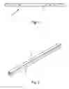
FIG. 1 shows a front view of a device of the invention in the closed position,
FIG. 2 shows a perspective view of a device of the invention in the closed position,
FIG. 3 shows a side view of the device of the invention in a partially open position,
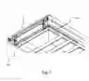
FIG. 4 shows a perspective view of a device of the invention in a partially open position,
FIG. 5 shows a front view of a device of the invention in a partially open position,
FIG. 6 shows a perspective view of a device of the invention in a partially open position,
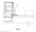
FIG. 7 shows a device of the invention mounted to a bed by means of an interposed structure,
FIG. 8 shows a device of the invention mounted to a bed in another position and with a blanket resting thereon,
FIG. 9 shows a side view of a device of the invention mounted to a bed with a blanket resting thereon,
FIG. 10 shows a detail of a preferred embodiment with a stop lug, and
FIG. 11 shows a perspective view of a device of the invention according to a preferred embodiment in an open position.
DETAILED DESCRIPTION OF THE INVENTION
Numeral 1 designates the airing device of the invention, which is designed to air out blankets 200 and the like. The device comprises a crosspiece 2. The term crosspiece is intended to designate an element such as a plate made of metal, wood, plastic or the like. This plate that forms the crosspiece 2 is adapted to be connected to a bed structure 100. The connection may be provided by means of a number of screws or nails or bonding to the bed. These are examples of connection. The connection may be provided directly with an interposed element, for example a metal corner element or the like. At least two first tubular profiles 3, 4 are connected by one end to the crosspiece 2. The term tubular profile 3.4 is intended to designate a body having a longitudinal extension with a central hole. These tubular profiles 3,4 are adapted to pivot about a first axis 5 perpendicular to the crosspiece 2.
The orientation may be preferably limited to a maximum opening amplitude of about 90° relative to the crosspiece 2 by means of a stop 50.
A lock member may be preferably provided, that locks the tubular profiles 3, 4 in the deployed position.
A spring element 6 is placed in each first tubular profile 3, 4. This spring element 6 is advantageously an elastic strap made of plastic, rubber or the like.
The spring element 6 of each first tubular profile 3.4 extends through at least one second tubular profile 7.8 and connects it with the first tubular profile 3. 4.
The second tubular profiles connected to a support surface 9 for a blanket or the like are adapted to pivot about a second axis 10 perpendicular to the support surface 9.
At least one element 11 that forms a seat is provided on the first or second tubular profiles. This seat may be an enlargement of one of the tubular profiles or an element that is rigidly fixed to the first tubular profiles 3 or the second tubular profiles 7, 8, for fastening the first tubular profiles 3 to the second tubular profiles 7.8. This element has an inner diameter that is greater than the tubular profile to be inserted therein.
Such fixation is obtained by displacement of the first tubular profile 3, 4 or the second tubular profile 7, 8 to insert it into the element 11. Thus, the two tubular profiles 3, 4,7, 9 are maintained in their position by means of the elastic strap, band or thread.
The elastic strap is pre-loaded before deployment of the device 1 of the invention. This will help the structure to assume its mounted form, in which it is adapted to air out a blanket 200. In one embodiment, the crosspiece 2 and/or the support surface 9 for the blanket 200 are connected with two side walls 20, 21, 30, 31. In their closed position, these side walls form an assembly with the crosspiece 2 and the surface 9 for receiving the tubular profiles 3, 4, 7, 8. Thus, in the undeployed form, the device is very compact and may be also quickly transported. This compact form is particularly obtained because the first tubular profiles 3, 4 are laterally displaced. These and the second tubular profiles 7, 8 are adjacent in the closed state. By this arrangement deployment becomes easier and quicker, because the lateral supports provided by the first tubular profile 3 and the second tubular profile do not interfere with each other during deployment and closing.
In a different embodiment at least one stop member 50,51, 52, 53 may be provided to create an outward stop arrangement for the profile 3, 4, 7 and 8. This stop member is placed in the crosspiece 2 and/or the support 9.
Preferably, two stop members 50, 51 are arranged in the airing device 1. The two stop members 50,51 at the ends of the crosspiece provide support to the tubular profiles 3. In a preferred embodiment the stop surface of the stop member 50, 51 has a smaller size than the height of the airing device 1. This will allow the stop members 50, 51 to be enclosed in the closed airing device for 1 by the side walls 20, 21,30, 31.
Also, in a preferred embodiment the stop members arranged in the crosspiece 2 are complementary to the widthwise displaced stop members 52, 53 arranged in the support 9.
In a preferred embodiment, the ends of the tubular profiles 3, 4, are pivotally connected with the crosspiece 2 and the tubular profiles 7 are pivotally connected with the support 9 by means of blocks 55. Thus, the stop members 52, 53 will form stops for the tubular profiles 7, 8.
Finally, it shall be understood that the above description is susceptible of additions, changes or variants that would be obvious to the skilled person, without departing from the scope of the invention as defined by the appended claims.
REFERENCE NUMBERS
- 1 Airing device
- 2 crosspiece
- 3 first tubular profile
- 4 first tubular profile
- 5 first axis
- 6 spring element
- 7 second tubular profile
- 8 second tubular profile
- 9 support
- 10 second axis
- 11 element/seat
- 20 side wall
- 21 side wall
- 30 side wall
- 31 side wall
- 50 stop member
- 51 stop member
- 52 stop member
- 53 stop member
- 55 block
- 100 bed
- 200 blanket
- 300 connecting structure
Claims
1. A device for airing out blankets and the like comprising a crosspiece, which is adapted to be connected to a bed structure, having at least two adjoining tubular profiles connected by one end, and pivoting about an axis perpendicular to the crosspiece, a spring element being placed in each tubular profile, said spring element of each first tubular profile extending through at least one second tubular profile and connecting it to a first tubular profile, the second tubular profiles being connected to a surface of a support for a blanket or the like and pivoting about an axis perpendicular to the surface of a support and an element being fixed on the first and the second tubular profiles, to form a seat for the tubular profile to be fixed, which is adapted to fix the first tubular profiles to the second tubular profiles, the first tubular profiles being laterally adjacent to each other, and the second tubular profiles being laterally adjacent to each other, and the first tubular profiles being vertically aligned with their respective second tubular profiles.
2. The device for airing out blankets and the like as claimed in claim 1, wherein the cross member and/or the support surface for the blanket are connected with two side walls thereby forming an assembly with the cross member and the support surface.
3. The device for airing out blankets and the like as claimed in claim 1, wherein the spring element is an elastic strap cord, or thread.
4. The device for airing out blankets and the like as claimed in claim 1, wherein a stop member is placed at least in the crosspiece and/or the support.
5. The device for airing out blankets and the like as claimed in claim 1, wherein the tubular profiles are pivotally connected with the crosspiece and the tubular profiles are pivotally connected with the support surface by means of blocks.
6. The device for airing out blankets and the like as claimed in claim 5, wherein two stop members are placed in the crosspiece and two stop members are placed in the support, the stop members being placed at the ends of the crosspiece and the support respectively and being complementary to each other.
Images & Drawings included:


Sources:
- United States Patent and Trademark Office - verify current appl. status at the USPTO↗
Recent applications in this class:
- » 20250120515 2025-04-17
BED SHEET RETENTION SYSTEMS, SYSTEM COMPONENTS, AND METHODS OF MAKING AND USING THE SAME - » 20250098868 2025-03-27
BED SHEET RETENTION SYSTEMS, SYSTEM COMPONENTS, AND METHODS OF MAKING AND USING THE SAME - » 20250064221 2025-02-27
COMFORTER BLANKET - » 20250057323 2025-02-20
NO-SLIP SHEET GRIP - » 20250031861 2025-01-30
BEDDING CONNECTION DEVICE, BEDDING SYSTEM AND PROCESS FOR CHANGING OF BED SHEETS - » 20250024957 2025-01-23
Fitted Sheet Device with Attachable Top Sheet - » 20250017388 2025-01-16
AN ARTICLE OF BEDDING - » 20250000270 2025-01-02
BEDDING SYSTEMS - » 20240341492 2024-10-17
Bedding System - » 20240292957 2024-09-05
Sheet Anchor Device