URINAL CAPTURE PORTION
US20190284789A1
2019-09-19
15/919,841
2018-03-13
Abstract:
One embodiment provides a urinal apparatus, including: a main body comprising a urinal bowl; and a raised capture portion positioned above a floor base and below the urinal bowl and extending away from the main body to a point past a distal edge of the urinal bowl.
Interested in similar patents?
Get notified when new applications in this technology area are published.
Classification:
E03D13/00 » CPC main
Urinals ; Means for connecting the urinal to the flushing pipe and the wastepipe; Splashing shields for urinals
Description
BACKGROUND
Individuals require sanitary facilities for urinating when not at home. For men, a commonly used sanitary plumbing fixture is a urinal, which is a bowl, or other receptacle, that is typically attached to a wall in a public restroom and allows for automatic or manual flushing of liquid waste. Urinals are prevalent in most locations in modern society and are intended to be a sanitary and easy-to-use apparatus for urine disposal.
BRIEF SUMMARY
In summary, one aspect provides a urinal apparatus, comprising: a main body comprising a urinal bowl; and a raised capture portion positioned above a floor base and below the urinal bowl and extending away from the main body to a point past a distal edge of the urinal bowl.
Another aspect provides a capture portion, comprising: sloped edges converging at an indented bottom portion; and an attachment mechanism capable of attaching to a main body of a urinal.
The foregoing is a summary and thus may contain simplifications, generalizations, and omissions of detail; consequently, those skilled in the art will appreciate that the summary is illustrative only and is not intended to be in any way limiting.
For a better understanding of the embodiments, together with other and further features and advantages thereof, reference is made to the following description, taken in conjunction with the accompanying drawings. The scope of the invention will be pointed out in the appended claims.
BRIEF DESCRIPTION OF THE SEVERAL VIEWS OF THE DRAWINGS
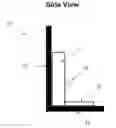
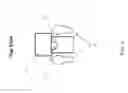
FIG. 1 illustrates a side view of a urinal apparatus comprising a capture portion according to an embodiment.
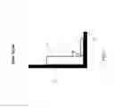
FIG. 2 illustrates another side view of a urinal apparatus comprising a capture portion according to an embodiment.
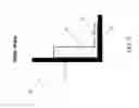
FIG. 3 illustrates a front view of a urinal apparatus comprising a capture portion according to an embodiment.
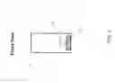
FIG. 4 illustrates a top view of a urinal apparatus comprising a capture portion according to an embodiment.
DETAILED DESCRIPTION
It will be readily understood that the components of the embodiments, as generally described and illustrated in the figures herein, may be arranged and designed in a wide variety of different configurations in addition to the described example embodiments. Thus, the following more detailed description of the example embodiments, as represented in the figures, is not intended to limit the scope of the embodiments, as claimed, but is merely representative of example embodiments.
Reference throughout this specification to “one embodiment” or “an embodiment” (or the like) means that a particular feature, structure, or characteristic described in connection with the embodiment is included in at least one embodiment. Thus, the appearance of the phrases “in one embodiment” or “in an embodiment” or the like in various places throughout this specification are not necessarily all referring to the same embodiment.
Furthermore, the described features, structures, or characteristics may be combined in any suitable manner in one or more embodiments. In the following description, numerous specific details are provided to give a thorough understanding of embodiments. One skilled in the relevant art will recognize, however, that the various embodiments can be practiced without one or more of the specific details, or with other methods, components, materials, et cetera. In other instances, well known structures, materials, or operations are not shown or described in detail to avoid obfuscation.
Oftentimes, during urinal use, errant urine from a user may fall onto the floor area between the user and the main body of the urinal instead of into the urinal bowl. Such an occurrence may lead to un-hygienic restroom facilities in which users are forced to step in the urine while navigating the restroom. Additionally, upon leaving the restroom, users may unknowingly spread urine residue, which may have collected on the soles of their shoes, to other areas of a building or space. Such a situation may be exacerbated when the restroom facility experiences high-traffic (e.g., at a sporting event, etc.). High-traffic restrooms require frequent cleaning in order to properly maintain the cleanliness of the space at an acceptable sanitary standard. As such, the maintenance of high-traffic restrooms is expensive, time-consuming, and resource intensive.
Conventional urinal designs have so far failed to overcome the issue of errant urine drip. Known conventional urinal designs comprise a connected or disconnected capture area that is positioned beneath the urinal bowl that is flush with the floor. However, an issue with such a configuration is that the capture area may not be immediately noticeable to a user, who may unintentionally step in the pooled urine of the flush capture area. As such, there are currently no designs on the market that address this problem to an appreciable extent.
Accordingly, an embodiment provides a urinal apparatus that overcomes the urine drip issues that are prevalent in existing urinal designs. In an embodiment, a urinal apparatus may comprise a main body having a urinal bowl. The urinal apparatus may further comprise a raised capture portion that is positioned beneath the urinal bowl, but above the ground, and extends away from the main body to a point past a distal edge of the urinal bowl. Stated differently, the capture portion may comprise dimensions that encompass areas around the urinal bowl that may be associated with a standard urine drip footprint. In some embodiments, the raised capture portion may be integrated into the urinal apparatus. In these embodiments, one or more pipes may be connected to the integrated raised capture portion so that any liquid captured in the integrated raised capture portion may be flushed (e.g., similar to how liquid is flushed in the urinal bowl, etc.). Other embodiments may provide a capture portion that is not integral with a urinal, but rather, is attachable to the urinal (e.g., via an attachment mechanism, etc.). The aforementioned embodiments may capture errant urine not captured by the urine bowl, thereby improving the cleanliness of restrooms and other proximate spaces.
The illustrated example embodiments will be best understood by reference to the figures. The following description is intended only by way of example, and simply illustrates certain example embodiments.
Referring now to FIGS. 1-3, a side view and front view of a urinal apparatus comprising a raised capture portion are illustrated according to a plurality of embodiments. In an embodiment, the urinal apparatus 10 may comprise a main body 11 having a urinal bowl 12. The main body 11 of the urinal may be mounted to a wall 13 (e.g., a wall of a restroom, etc.) and may extend down to a base 14 (e.g., a floor, etc.). Although FIG. 1 illustrates that the main body is extendable down to a base 14, such an illustration is non-limiting and other embodiments not illustrated here may allow the main body to terminate at a point above the base 14. In an embodiment, the urinal bowl 12 may be a receptacle configured to receive and hold liquid waste (e.g., urine, etc.). The urinal bowl 12 may comprise a shape capable of preventing backsplash to a user (e.g., reverse-cone shaped, substantially bowl-shaped, etc.) and may also comprise an existing liquid (e.g., water, disinfect, a combination thereof, etc.). The urinal apparatus may be equipped with a flushing mechanism (not illustrated) that is configured to flush the contents in the urinal bowl 12 through plumbing that is operatively connected to the urinal.
Depending on the configuration of the urinal, the urinal bowl 12 may be positioned and protrude from different points from the main body 11. For example, FIG. 1 illustrates an embodiment where the urinal bowl 12 is positioned at a bottom point of the main body 11. In this configuration, the urinal bowl 12 is positioned close to the base 14. Referring now to FIG. 2, another embodiment is illustrated in which the urinal bowl 12 is positioned at a predetermined point above the base 14 (e.g., 2 feet above the base 14, etc.).
In an embodiment, the urinal apparatus 10 may comprise a raised capture portion 15. The raised capture portion 15 may be integrally connected to the main body 11, for example, manufactured with the main body, or may be a separate piece that is manufactured separate from the main body 11. The raised capture portion 15 may be positioned at virtually any point beneath a top edge of the urinal bowl 12. For example, in FIG. 1, the raised capture portion 15 is positioned at a location directly beneath the entirety of the urinal bowl 12 and proximate to a base 14. In an embodiment, the raised capture portion 15 may be virtually any shape (e.g., a substantially oval shape, a substantially rectangle shape, substantially reverse-cone shaped, etc.) that comprises dimensions capable of encompassing areas outside and around the edges of the urinal bowl 12. For example, a raised capture portion 15 may extend 12-15 inches beyond the main body 11 of the urinal apparatus 10, be between 10-12 inches wide (e.g., sufficient to cover a standard urine drip area, etc.), and be between 3-5 inches high.
In an embodiment, the raised capture portion 15 may comprise “bowl-like” properties in that it may have sloped edges that converge at an indented bottom portion. In an embodiment, the raised capture portion 15 may comprise one or more holes for liquid drainage. The one or more holes may be located at the indented bottom portion. In an embodiment, plumbing (e.g., one or more pipes, etc.) may be operatively connected to the raised capture portion 15 to receive liquid drainage through the one or more holes and transport it away. In another embodiment, the urinal bowl 12 may comprise one or more holes (not pictured) at a bottom portion of the urinal bowl 12 so that liquid captured by the capture portion 15 may flow from the indented bottom portion of the capture portion 15 directly into the urinal bowl 12.
In an embodiment, the urinal apparatus 10 may comprise a flushing mechanism. In an embodiment, the flushing mechanism may be associated with a manual flushing mechanism (e.g., a hand lever, etc.), an automatic flushing mechanism (e.g., using a processor and one or more sensors, etc.), or a combination thereof. In an embodiment, the flushing mechanism may be configured to flush liquid drainage from the urinal bowl 12 and the raised capture portion 15 substantially simultaneously. For example, in the case of a manual flushing mechanism, when a user actuates a flushing lever of the urinal apparatus, the contents in both the urinal bowl 12 and the raised capture portion 15 are flushed simultaneously. Alternatively, in another embodiment, the flushing mechanism may be configured to automatically flush liquid drainage from the raised capture portion 15 after liquid drainage from the urinal bowl 12 has been flushed a predetermined number of times (e.g., three times, five times, etc.). For example, after a urinal bowl 12 of a particular urinal has been flushed four times, on the fifth flush, the contents of both, the urinal bowl 12 and the raised capture portion 15, are flushed together.
In yet a further embodiment, the flushing mechanism may be configured to automatically flush liquid drainage from the raised capture portion 15 after detecting that the contents in the raised capture portion 15 have exceeded a predetermined threshold amount. For example, the urinal apparatus 10 may comprise one or more sensors (e.g., liquid level detectors, pH detectors, etc.) capable of monitoring the liquid contents in the raised capture portion 15. Responsive to detecting that the liquid contents have exceeded a predetermined threshold (e.g., that the liquid level has reached a predetermined height, that the pH has reached a predetermined acidity, etc.), an embodiment may communicate this information to the flushing mechanism, which may thereafter flush the liquid contents in the raised capture portion 15 on the subsequent flush of the urinal bowl 12. In an embodiment, similar to the urinal bowl 12, the raised capture portion 15 may hold an existing liquid (e.g., water, disinfect, a combination thereof, etc.). The existing liquid in the raised capture portion 15 may be refilled after each flushing event.
Referring to FIG. 4, which illustrates a top view of a urinal apparatus 10, in an embodiment, the urinal apparatus 10 may comprise one or more lights (not illustrated) that may project an image of footprints 16 on the floor. The projected footprints 16 may serve as a suggested standing area for a user. The one or more lights may be integral to the urinal apparatus 10 and may be positioned, for example, at a lower portion of the main body of the urinal (e.g., on a bottom side of the urinal bowl 12, etc.) in order to project the image onto the floor.
In the aforementioned embodiments, aspects of the capture portion have been described with the consideration that the capture portion is integral to the urinal. However, as previously mentioned, the capture portion may not be integral to the urinal apparatus, but rather, may be a separate unit that is attachable to the main body of the urinal.
In an embodiment, an attachable capture portion is provided that may be easily attachable and securable to a main body of a urinal. The attachable capture portion may be attachable to a portion of the main body of the urinal at some point beneath a top edge of the urinal bowl. In an embodiment, the attachable capture portion may comprise dimensions similar to the dimensions of the raised capture portion described above (i.e., dimensions large enough to capture errant urine outside the edges of the urinal bowl) and may be composed of a lightweight material (e.g., plastic, etc.) that allows a user to easily attach and detach the attachable capture when need be. In an embodiment, the attachable capture portion may comprise an attachment mechanism that allows for attachment of the attachable capture portion to the main body of the urinal. In an embodiment, the attachment mechanism may be one or more conventional mechanisms allowing for attachment of one object to another (e.g., a strong adhesive portion, a Velcro® system, clips or hooks integrated into the capture portion, etc.).
In an embodiment, the attachable capture portion may be visually distinguished from other parts of the urinal. For example, the attachable capture portion may have a particular color (e.g., red, black, green, etc.) that is visually different than conventional urinal colors (e.g., white, tan, etc.). The distinguishing color of the attachable capture portion may serve to alert users of the presence of the capture portion so that they do not accidently step into it (e.g., if the capture portion was placed proximate to the floor, etc.).
The various embodiments described herein thus represent a technical improvement to conventional urinals. Using the products and designs described herein, an embodiment may capture errant urine drip in a capture portion (e.g., integral raised capture portion, attachable capture portion, etc.) that may be located at a point underneath a urinal bowl of the urinal. The errant urine drip that is captured in this capture portion may be disposed of automatically (e.g., in the case of an integral capture portion, the errant urine drip may be flushed away along with the liquid waste in the urinal bowl, etc.) or may be disposed of manually (e.g., in the case of an attachable capture portion, the capture portion may be detached by a user and emptied, etc.). Such a product serves to improve the sanitary conditions of restrooms and proximate spaces by drastically reducing, if not eliminating, the amount of urine that ends up on the floor.
As used herein, the singular “a” and “an” may be construed as including the plural “one or more” unless clearly indicated otherwise.
This disclosure has been presented for purposes of illustration and description but is not intended to be exhaustive or limiting. Many modifications and variations will be apparent to those of ordinary skill in the art. The example embodiments were chosen and described in order to explain principles and practical application, and to enable others of ordinary skill in the art to understand the disclosure for various embodiments with various modifications as are suited to the particular use contemplated.
Thus, although illustrative example embodiments have been described herein with reference to the accompanying figures, it is to be understood that this description is not limiting and that various other changes and modifications may be affected therein by one skilled in the art without departing from the scope or spirit of the disclosure.
Claims
1. A urinal apparatus, comprising:
a flushing mechanism;
a main body comprising a urinal bowl; and
a raised capture portion positioned above a floor base and below the urinal bowl and extending away from the main body to a point past a distal edge of the urinal bowl
wherein the flushing mechanism is configured to automatically flush liquid drainage collected in the raised capture portion at a predetermined point.
2. The urinal apparatus of claim 1, wherein the raised capture portion is positioned at a bottom portion of the main body.
3. The urinal apparatus of claim 1, wherein the raised capture portion extends 12-15 inches past the distal edge of the urinal bowl.
4. The urinal apparatus of claim 1, wherein the raised capture portion is 10-12 inches wide.
5. The urinal apparatus of claim 1, wherein the raised capture portion is 3-5 inches tall.
6. The urinal apparatus of claim 1, wherein the raised capture portion is substantially rectangular shaped.
7. The urinal apparatus of claim 1, wherein the raised capture portion comprises sloped edges converging at an indented bottom portion.
8. The urinal apparatus of claim 7, wherein the indented bottom portion comprises one or more holes for liquid drainage.
9. The urinal apparatus of claim 8, wherein the one or more holes are one or more holes of a bottom portion of the urinal bowl.
10. The urinal apparatus of claim 8, further comprising a pipe attached to the raised capture portion and capable of receiving the liquid drainage through the one or more holes.
11. (canceled)
12. The urinal apparatus of claim 1, wherein the predetermined point is a point at which liquid drainage from the urinal bowl is flushed.
13. The urinal apparatus of claim 1, wherein the predetermined point is a point at which liquid drainage from the urinal bowl has been flushed a predetermined amount of times.
14. The urinal apparatus of claim 1, wherein the predetermined point is a point at which liquid drainage in the raised capture portion is detected to have exceeded a predetermined threshold amount.
15. The urinal apparatus of claim 1, wherein the raised capture portion comprises an existing liquid base, the existing liquid base comprising at least one of water and disinfectant.
16. The urinal apparatus of claim 1, further comprising one or more lights capable of projecting a footprint image on the floor base.
17. A capture portion, comprising:
sloped edges converging at an indented bottom portion; and
an attachment mechanism capable of attaching to a main body of a urinal.
18. The capture portion of claim 17, wherein the capture portion is attachable to the main body of the urinal located beneath a urinal bowl of the main body.
19. The capture portion of claim 17, wherein the capture portion is plastic.
20. The capture portion of claim 17, wherein the capture portion is visually distinguished from the urinal.
Images & Drawings included:
Sources:
- United States Patent and Trademark Office - verify current appl. status at the USPTO↗
Recent applications in this class:
- » 20250163692 2025-05-22
Splash Reducing Surfaces - » 20250116102 2025-04-10
Home/Portable Urinal - » 20250075486 2025-03-06
Urinal Device - » 20240410154 2024-12-12
URINAL - » 20240328140 2024-10-03
URINAL - » 20240191487 2024-06-13
URINAL UNIT - » 20230272611 2023-08-31
SYSTEMS, METHODS, AND DEVICES RELATING TO A URINAL - » 20230272610 2023-08-31
URINAL WITH SHOWER FUNCTION FOR THE PENIS - » 20230073555 2023-03-09
MANAGEMENT SYSTEM, DETECTION DEVICE, ESTIMATION DEVICE, AND PERFORATED PLATE - » 20220120072 2022-04-21
Systems, methods, and devices relating to a urinal