Multilevel converter for the control and transmission of electrical energy
US20200028445A1
2020-01-23
16/334,942
2017-09-20
✅ Patent granted
US 11,018,600 B2
2021-05-25
WO; PCT/CL2017/050053; 20170920
WO; WO2018/053660; 20180329
Adolf D Berhane | Afework S Demisse
Ladas and Parry LLP
2037-10-02
Abstract:
A multilevel converter operating with fewer components saving costs, losses, size and weight, allowing the reduction of volume and accessibility to the control and transformation of electric power, comprising at least a basic cell formed by: a) a first power switch that interconnects the positive bus between said at least one basic cell and at least another basic cell connected in cascade each other and/or a basic cell and a continuous voltage source; b) a second power switch that interconnects the negative bus between said at least one basic cell and at least another basic cell connected in cascade each other; and/or a basic cell and the continuous voltage source of point a); and c) a capacitor with a third power switch, both of them being connected in series each other and interconnected between the positive and negative bus.
Inventors:
- Margarita NORAMBUENA VALDIVIA 1 🇨🇱 VALPARAÍSO, Chile
- José RODRIGUEZ PÉREZ 1 🇨🇱 VIÑA DEL MAR, Chile
- Samir KOURO RAENER 1 🇨🇱 VALPARAÍSO, Chile
- Margarita NORAMBUENA VALDIVIA 2 🇨🇱 Valparaiso, Chile
- Jose RODRIGUEZ PEREZ 2 🇨🇱 Vina del Mar, Chile
- Samir Kouro Renaer 1 🇨🇱 Valparaíso, Chile
Assignee:
- Universidad Tecnica Federico Santa Maria 17 🇨🇱 Valparaiso, Chile
- UNIVERSIDAD ANDRÉS BELLO 2 🇨🇱 SANTIAGO, Chile
- UNIVERSIDAD TÉCNICA FEDERICO SANTA MARÍA 1 🇨🇱 VALPARAÍSO, Chile
- UNIVERSIDAD ANDRES BELLO 4 🇨🇱 Santiago, Chile
Applicant:
Interested in similar patents?
Get notified when new applications in this technology area are published.
Classification:
H02M7/5387 » CPC further
Conversion of ac power input into dc power output; Conversion of dc power input into ac power output; Conversion of dc power input into ac power output without possibility of reversal by static converters using discharge tubes with control electrode or semiconductor devices with control electrode using devices of a triode or transistor type requiring continuous application of a control signal using semiconductor devices only, e.g. single switched pulse inverters in a bridge configuration
H02M7/003 » CPC further
Conversion of ac power input into dc power output; Conversion of dc power input into ac power output Constructional details, e.g. physical layout, assembly, wiring or busbar connections
H02M7/00 IPC
Conversion of ac power input into dc power output; Conversion of dc power input into ac power output
H02M7/487 » CPC main
Conversion of ac power input into dc power output; Conversion of dc power input into ac power output; Conversion of dc power input into ac power output without possibility of reversal by static converters using discharge tubes with control electrode or semiconductor devices with control electrode; Converters with outputs that each can have more than two voltages levels Neutral point clamped inverters
Description
The present invention refers to the conversion of electrical energy operating with fewer components, saving costs, losses, size and weight, allowing volume reduction and accessibility to the transformation of electrical energy for use in different applications, more specifically to a Multilevel Converter for the control and transformation of electrical energy within the scope of power electronics.
DESCRIPTION OF PRIOR ART
The technological development experienced by all areas of our society in the last forty years is mostly due to the progress made in power electronics. This branch of technology is responsible for transforming the different modes of use of electric power to adapt it to multiple applications such as speed control of electric motors, operation of household appliances (household appliances, computers, etc.), communications equipment, control of industrial processes and equipment, as well as in the field of generation, transport, distribution and storage of electrical energy.
In our current society, electric power is a fundamental pillar in the different activities developed every day, both the use and transport of it.
The nature of electric power imposes a number of requirements for its production and transport that are very different from other types of energy. Parameters such as voltage, the signal form, frequency and power factor are subject to certain limits in order to guarantee the stability of the network and the correct supply of electricity at points of consumption. The way of generating electrical energy, however, is not uniform and each energy source produces it in a particular way, presenting a wide variety of values for the different parameters mentioned above. The alternating-direct electronic converters (AC/DC) that feed the transport lines under high voltage direct and alternating current (HVDC and HVAC) and the direct-direct converters (DC/DC) that adapt the voltage of the batteries to the different microelectronic circuits (electric cars) are clear examples of application where a transformation of electrical energy with the highest possible output is required.
An energy converter is an electronic equipment or system that aims to convert electrical energy between two different formats, as for example, obtaining direct current from alternating current. The initial concept of the converter can extend to include such aspects such as: efficiency, reversibility, ideality degree, reliability, volume or technology, as the most important.
The converters can be classified according to different criteria. One of the most commonly used is to group them according to the format of the input and output energies. Basically and according to this criterion four large groups can be established:
-
- AC/AC converters.
- AC/DC converters or rectifiers.
- DC/DC converters.
- DC/AC converters or inverters.
The transmission of electrical energy requires in its points of connection and distribution, of equipment that transform the energy from one medium to another. Said equipment, being called Power Converters, have been widely developed and studied, those that allow the generation of multilevel voltage at the output being currently used.
The multilevel converters include an array of power semiconductors and capacitors as voltage sources; the voltage generated at the output has stepped wave form considering that the switches close and open at different times; depending on the number of power switches the voltage at the output grows adding the voltage of the capacitors, while the power switches support reduced voltages.
Multi-level converters with voltage fed have emerged as a new converter option for high power applications. There are different topologies of multilevel converters; however, they can be classified into three basic structures:
-
- Diode-Clamped Converter or NPC (Neutral Point Clamped Converter)).
- Flying Capacitor Multilevel Converter.
- Cascade Full-Bridge Multilevel Converter).
| TABLE 1 |
| Advantages and Disadvantages of Multilevel Converters |
| TYPE OF | ||
| CONVERTER | ADVANTAGES | DISADVANTAGES |
| NPC | Low content of harmonics | Too much claimed converters |
| Highly efficient converter | Flow of actual power had to | |
| control | ||
| Simple control method | Depending on the way direct | |
| voltage is Obtained. | ||
| unbalances can produce | ||
| among capacitors | ||
| Flying Capacitor | The modular technology allows | Excess number of capacitors |
| increasing the number of levels at | ||
| the output in a simple way | ||
| Extra switching combination to | The Converter control is | |
| balance the levels of voltage | complex when ensuring the | |
| right balance of capacitors | ||
| Control of actual and active | ||
| power | ||
| Cascade Full-Bridge | Fewer number of componentes | Independent DC sources are |
| Redesigning the power stage is | necessary for each cell | |
| not necessary | ||
| The semiconductor devices | ||
| handle only the voltage present in | ||
| a DC source | ||
The main advantage of multilevel converters is the reduction of harmonic components in the electrical variables. These equipments are also used for the transformation of energy in such applications as motors and drives.
There is a wide variety of Multilevel Converters in the state of the art. This is how the patent application CL 201202458, dated Sep. 4, 2012, of the inventor Ruiz Caballero Domingo Antonio, discloses a hybrid inverter multilevel reducer and or voltage booster for applications wherein the continuous voltage input being of a low value or with a great variation.
The patent document EP20050405463, dated Feb. 7, 2007, from the inventors Stefanutti Philippe; Zueger Harry; Hugo Nicolas; Dormia Georges; Descollaz Bernard, entitled “Transformer arrangement and multilevel converter”, describes a multilevel converter, with two converter levels (N=2), with each level including a primary converter connected to a primary winding of a transformer unit, a secondary converter connected to a secondary winding of the transformer unit, and a transformer core structure defining a closed magnetic flux path for magnetically coupling the primary and secondary windings. The converter is characterized in that the transformer core structures of a first and second transformer unit form a shared core with a return defining a shared section of the respective closed magnetic flux paths of the primary and secondary transformer unit.
The patent document U.S. Pat. No. 6,697,271 B2 dated Feb. 24, 2004, from the inventor Corzine Keith Allen, entitled “CASCADED MULTI-LEVEL H-BRIDGE DRIVE”, describes a multi-level inverter that is constructed by cascading several levels of H bridge inverters, and provides different voltage inputs to the additional multilevel converters. The voltage values are selected in order to provide a greater number of output levels. This arrangement can provide up to fifteen output levels if regenerative voltage sources and up to eleven output levels are used if a non-renewable voltage source is used.
The patent application document US201313955607, dated Jul. 31, 2013, from the inventors Andrew Allen Rockhill, Di Zhang, Luis Jose Garces, entitled “Multilevel converter system”, describes a power converter including at least one phase with a plurality of switching units, wherein said switching units are coupled together in such a way that at least two switching units have different operating voltages.
The patent application document WO2015131931, dated Sep. 11, 2015, from the inventors Amel Lachichi; Frans Dijkhuizen; Mats Hytlinen; Muhammad Nawaz; Nan Chen, entitled “MULTILEVEL CONVERTER”, discloses a multilevel converter comprising a half-bridge module having a capacitor unit and at least two switches, a door unit configured to control the switches, an electrical conductor, at least one first and second terminal portion and a subcell.
The patent application WO2015041691 dated Mar. 26, 2015, from the inventors Fan Shengfang; Xue Yaosuo, entitled “A NEW FOUR-LEVEL CONVERTER CELL TOPOLOGY FOR CASCADED MODULAR MULTILEVEL CONVERTERS”, discloses a cascaded modular multi-level converter having a plurality of 4-level converters, where each AC phase generates voltage waveforms of compound multiple levels with different output. Each module is a controlled voltage source. The number of voltage levels in the cascaded converter is determined by the number of modules in each phase and the voltage levels generated by each module.
One of the current main problems of all these multilevel converters is their size, weight and cost, which limit their accessibility and maneuverability.
This problem opens up the possibility of introducing a new topology capable of reducing its volume, the number of components used, the associated cost and the losses involved.
BRIEF DESCRIPTION OF THE FIGURES
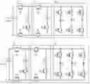
FIG. 1 shows a three-phase converter formed by two basic cells of the present invention.
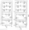
FIG. 2A (Prior Art) shows a 3-level commercial back-to-back converter.
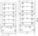
FIG. 2B shows the converter of the present invention for the case of 3 levels and 6 phases, 3 inputs and 3 outputs, which allows having a back-to-back connection.
DETAILED DESCRIPTION OF THE INVENTION
The present invention discloses a multilevel converter to perform the conversion of electrical energy operating with fewer components saving costs, losses, size and weight, allowing the reduction of volume and accessibility to the transformation of electric power for use in various applications
The multilevel converter of the present invention comprises a basic cell formed by a capacitor and three power switches (IGBT or MOSFET), each cell providing an additional level to the output. The output of the converter is generated through the connection of two power switches per phase.
As shown in FIG. 1, the basic cells (11′ and 11) are connected in cascade, wherein each basic cell (11′ and 11) is formed by:
-
- a) a power switch (S4, S1) that interconnects the positive bus between the basic cells (11′, 11) in contiguous series and/or between a basic cell (11′) and a continuous voltage source (represented by C3);
- b) a power switch (S6, S2) that interconnects the negative bus between the basic cells (11′, 11) in contiguous series and/or between a basic cell (11′) and the continuous voltage source of the previous point (represented by C3); and
- c) a capacitor (C1, C2) with a power switch (S5, S3) connected in series between the positive and negative bus.
The output (12) of each phase of the converter (1) is obtained at the midpoint of two power switches connected in series with each other and in parallel between the positive and negative pole of the last basic cell of the converter. So, there are two first power switches (S7, S7) connected in series for the output phase A, two second power switches (S8, S8) connected in series for the output stage B and two third power switches (S9, S9) connected in series for the output phase C. All these power switches are connected in parallel to the last basic cell that has the multilevel converter of the present invention.
The number of levels generated at the output of the converter is given by the equation:
Nn=Nc+2
Wherein Nn corresponds to the number of levels obtained and Nc to the number of basic cells that form the converter.
Therefore, each connected basic cell brings an additional level to the output. The number of voltage levels generated is independent of the number of outputs used, whether for 1 phase, 3 phases, 6 phases or Nf phases. Only 3 basic cells connected in series are required to have 5 voltage levels in each of the output phases regardless of the number they are; the only thing that varies with changing the number of output phases is the number of power switches in series connected in parallel to the last connected basic cell.
FIG. 1 shows the detail of the basic cell and the configuration for three independent outputs (A, B, C) (three-phase converter). Since in this case the converter is made up of two basic cells Nc=2, the number of levels obtained in each of the phases corresponds to Nn=4. The capacitor C3 in the topology shown is the continuous link, the converter performing the conversion of alternate to continuous power and vice versa.
FIG. 2A shows two commercial converters of floating capacitors of three voltage levels to a first output (21) and a second output (22). Each of these converters is identical to the other and has three output phases: A, B, C on the first output (21) and U, V, W on the second output (22); this type of configuration is known as a back-to-back connection, since both converters are connected through the continuous link. In FIG. 2A, this continuous voltage link is represented by the C3 capacitor. The floating capacitor converter is composed of a basic cell (23) that is formed by two power switches and a capacitor. Finally, the output of each phase is made up of two power switches. In total, for a back-to-back configuration of a floating capacitor converter with 3 voltage levels, a total of 24 power switches and 6 capacitors plus the continuous link capacitor are required.
FIG. 28 shows the topology of the present invention in a back-to-back configuration with three voltage levels at the output of each phase, such as the converter of FIG. 2A. The outputs A, B, C in the first output (25) correspond to the same three phases shown in the first output (21) of FIG. 2A, while the outputs U, V, W in the second output (26) correspond to the three phases shown in the second output (22) of FIG. 2A. The present invention requires a basic cell (24) to generate three voltage levels at each output of the converter, such as the floating capacitor converter (23) of FIG. 2A, the difference being that the proposed invention only requires one cell, independent of the number of output phases required, as shown in FIG. 2B, while the commercial topology requires one cell for each output phase (21, 22). The C2 capacitor of FIG. 2B corresponds to the continuous link capacitor between input A, B, C and the output U, V, W.
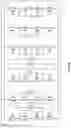
Table 2 shows a numerical comparison of the number of components for various multilevel topologies currently in the market and the proposal of the present invention.
| TABLE 2 |
| Comparative table of converters with 6 output phases |
| (back-to-back) |
| No OF | ||||
| CAPACITORS | ||||
| No OF | No OF | No OF | (Including C of DC- | |
| LEVELS | TOPOLOGY | SWITCHES | DIODES | Link) |
| 3 | NPC | 24 | 12 | 2 |
| Flying | 24 | 0 | 7 | |
| Capacitor | ||||
| Present | 15 | 0 | 2 | |
| Invention | ||||
| 5 | NPC | 48 | 72 | 4 |
| Flying | 48 | 0 | 19 | |
| Capacitor | ||||
| Present | 21 | 0 | 4 | |
| Invention | ||||
Claims
1. A multilevel converter operating with fewer components saving costs, losses, size and weight, allowing the reduction of volume and accessibility to the control and transformation of electric power, characterized in that comprising at least one basic cell formed by:
a) a first power switch that interconnects the positive bus between said at least one basic cell and at least another basic cell connected in cascade each other;
b) a second power switch that interconnects the negative bus between said at least one basic cell and at least another basic cell connected in cascade each other; and
c) a capacitor with a third power switch, both of them being connected in series each other and interconnected between the positive and negative bus.
2. A multilevel converter operating with fewer components saving costs, losses, size and weight, allowing the reduction of volume and accessibility to control and the transformation of electric power, characterized in that comprising at least one basic cell formed by:
a) a first power switch that interconnects the positive bus between said at least one basic cell and a continuous voltage source;
b) a second power switch that interconnects the negative bus between said at least one basic cell and a continuous voltage source; and
c) a capacitor with a third power switch, both of them being connected in series each other and interconnected between the positive and negative bus.
3. The multilevel converter according to claim 1, characterized in that the output of each multilevel converter phase is obtained at the midpoint of two output power switches connected in series each other and in parallel between the positive and negative pole of the last basic cell connected of the converter.
4. The multilevel converter according to claim 3, CHARACTERIZED in that the number of voltage levels generated by output phase is given by:
Nn=Nc+2
wherein Nn corresponds to the number of voltage levels obtained between an output phase and the multilevel converter neutral, and Nc to the number of basic cells that form the multilevel converter.
5. The multilevel converter according to claim 4, characterized in that the number of voltage levels obtained is independent from the number of outputs used, whether for one phase, three phases, six phases or Nf phases.
6. The multilevel converter according to claim 2, characterized in that the output of each multilevel converter phase is obtained at the midpoint of two output power switches connected in series each other and in parallel between the positive and negative pole of the last basic cell connected of the converter.
Images & Drawings included:
Sources:
- United States Patent and Trademark Office - verify current appl. status at the USPTO↗
Recent applications in this class:
- » 20250293617 2025-09-18
CONVERTER AND ANPC CIRCUIT DRIVING METHOD THEREFOR - » 20250226765 2025-07-10
POWER SUPPLY QUALITY IMPROVEMENT-ORIENTED AND FAULT CONTROL-ORIENTED ECONOMICALLY-INTEGRATED MEDIUM-VOLTAGE GRID-CONNECTED DEVICE WITH SiC MODULE AND ADAPTIVE CONTROL METHOD THEREFOR - » 20250226764 2025-07-10
SYSTEMS AND METHODS TO REDUCE THE DC LINK CAPACITANCE AND IMPROVE THE RELIABILITY OF CONVERTERS - » 20250211132 2025-06-26
Photovoltaic Inverter and Control Method Thereof - » 20250183814 2025-06-05
POWER CONVERSION DEVICE - » 20250141367 2025-05-01
ELECTRICAL POWER CONVERTER - » 20250125744 2025-04-17
CONTROL UNIT FOR POWER CONVERTER, AND POWER CONVERSION APPARATUS - » 20250105758 2025-03-27
THREE-LEVEL POWER SEMICONDUCTOR MODULE AND ARRANGEMENT THEREWITH - » 20250105757 2025-03-27
THREE-LEVEL POWER SEMICONDUCTOR MODULE AND ARRANGEMENT THEREWITH - » 20250088119 2025-03-13
Interleaved Active Neutral Point Clamped (ANPC) Circuit
Recent applications for this Assignee:
- » 20220107214 2022-04-07
Sensor device and system for in-line measurement of superficial gas velocity, forth depth, apparent density and holdup in flotation cells - » 20210299196 2021-09-30
Pharmaceutical composition based on bacteriophages against ; use in the treatment of diseases associated with this pathogen - » 20210181697 2021-06-17
Method for sequential predictive control, first solving a cost function and subsequently a second cost function for two or more control objectives - » 20210148818 2021-05-20
System and method for black carbon (BC) mass concentration determination in snow samples and similar matrices - » 20200353644 2020-11-12
Automatic formwork system and method for flexible elastic membrane moulds - » 20200296978 2020-09-24
Modified 1-methylcyclopropene (1-MCP) nanobubbles - » 20200277896 2020-09-03
SYSTEM AND METHOD TO STORE AND GENERATE ENERGY WHERE A PRESSURE IS RELEASED INTO A LIQUID CIRCUIT WHICH IN TURN MOVES A LIQUID TURBINE TO GENERATE POWER - » 20190365670 2019-12-05
Method for producing a sea urchin extract enriched with 1,4-polyhydroxylated naphthoquinones with antimicrobial and antioxidant activity - » 20190233942 2019-08-01
Method and system for producing graphene on a copper substrate by modified chemical vapor deposition (AP-CVD) - » 20190147593 2019-05-16
Method for estimating force and pressure of collision in vocal cords from high-speed laryngeal videos