Harker oceanic power station
US20200049124A1
2020-02-13
15/998,367
2018-08-09
Abstract:
1. Remove original Specifications and Replace with updated version.
-
- a. 4 deletions of underlines (one with text type change).
- b. 14 changes or additions (including an “s” on “turbine” in “FIG. 2” para, 5th line).
- c. 1 new FIG. 3/paragraph
- d. Add the claim 1—(Original).
Interested in similar patents?
Get notified when new applications in this technology area are published.
Classification:
F03B13/22 » CPC main
Adaptations of machines or engines for special use; Combinations of machines or engines with driving or driven apparatus ; Power stations or aggregates characterised by using wave or tide energy using wave energy using the flow of water resulting from wave movements to drive a motor or turbine
F16H7/06 » CPC further
Gearings for conveying rotary motion by endless flexible members with chains
Description
DESCRIPTION OF VIEWS
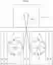
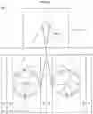
FIG. 1A
Top View-Top Half. The Harker Oceanic Power Station has two levels. The top is where the clutch/gearbox (A) is located. The clutch/gearbox (A) would be mechanically connected to a generator(s) or other device(s) for producing electricity or other services.
FIG. 1B
Top View-Bottom Half. The bottom is a pillar (B) design with turbines (C) placed alternately with the pillars. The turbines (C) and the gearbox (A) are mechanically connected by drive chains (D). The pillars (B) are shaped so that as the ocean waves pass between them, Bernoulli's Principle would speed the water's velocity up for more turbine speed. The power station can be built with varying number of turbines.
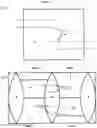
Front View. The turbine (C) on one side is shaped so that ocean waves (FIG. 1B, Water A) coming in towards the shoreline turn the turbine (C) to drive the chain (D) that turns the gearbox (A). While the other turbine (C) is shaped reverse and is “freewheeling” on a ratchet (E), just like a bicycle gear does when the rider turns the pedals backwards. The ratchet (E) located on the outer edge of the turbines (C) between the turbine (C) and the chain (D). Then when the wave switches direction and the water is returning to the ocean (FIG. 1B, Water B), what was the drive turbine (C) becomes the “freewheeling” turbine (C) and what was the “freewheeling” turbine (C) becomes a drive turbine (C) turning the chain (D) that turns the gearbox (A).
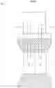
Side View. Shows a cutaway view of the station. The turbines (C) are shown offset from each other, just as in FIG. 1B.
Claims
1. The ratcheted-turbines (E)-(C) are a new use of machine and process. The turbines (C) being designed for opposite drive direction and the ratchets (E) located between the turbines (C) and the drive chains (D) is what makes the idea one of a kind in the world.
Images & Drawings included:
Sources:
- United States Patent and Trademark Office - verify current appl. status at the USPTO↗
Recent applications in this class:
- » 20250172120 2025-05-29
A SYSTEM FOR CONVERTING KINETIC POWER TO HYDRAULIC POWER USING A MEMBRANE AND A FIRST LIQUID ON A PRIMARY SIDE OF THE MEMBRANE AND A SECOND LIQUID ON A SECONARY SIDE OF THE MEMBRANE - » 20250172119 2025-05-29
KINETIC ENERGY RECOVERY WIND-WAVE INTEGRATED SYSTEM - » 20250129763 2025-04-24
WAVE POWER GENERATION SYSTEM - » 20250101941 2025-03-27
PRESSURE-REGULATING HYDRODYNAMIC PUMP AND WAVE ENGINE - » 20240376858 2024-11-14
WAVE ENERGY POWER GENERATION DEVICE AND POWER GENERATION METHOD - » 20240229760 2024-07-11
OCEAN WAVE AND TIDAL CURRENT ENERGY CONVERSION SYSTEM - » 20240141864 2024-05-02
Pressure-regulating hydrodynamic pump and wave engine - » 20240141863 2024-05-02
Wave energy conversion device - » 20240110541 2024-04-04
SELF-POWERED COMPUTING BUOY - » 20240084775 2024-03-14
Wave energy converter