Wide-angle lens assembly
US20200073086A1
2020-03-05
16/299,262
2019-03-12
✅ Patent granted
US 11,187,874 B2
2021-11-30
-
-
Mahidere S Sahle
McClure, Qualey & Rodack, LLP
2039-09-25
Abstract:
A wide-angle lens assembly includes a first lens, a second lens, a third lens, a fourth lens, a fifth lens, a sixth lens, a seventh lens, an eighth lens, and a ninth lens. The first lens has negative refractive power and includes a concave surface facing an image side. The second lens has negative refractive power and includes a concave surface facing the image side. The third lens has negative refractive power and includes a concave surface facing the image side. The fourth, fifth, seventh and eighth lenses have refractive power. The sixth and ninth lenses are biconvex lenses with positive refractive power. The first to ninth lenses are arranged in order from an object side to the image side along an optical axis.
Inventors:
- Tao Fu 15 🇨🇳 Shenzhen City, China
- Tao Fu 16 🇨🇳 Shenzhen, China
- An-Kai Chang 9 🇹🇼 Taichung, Taiwan
Assignee:
- ASIA OPTICAL CO., INC. 473 🇹🇼 Taichung, Taiwan
- SINTAI OPTICAL (SHENZHEN) CO., LTD. 90 🇨🇳 Shenzhen, China
Applicant:
Interested in similar patents?
Get notified when new applications in this technology area are published.
Classification:
G02B13/06 » CPC further
Optical objectives specially designed for the purposes specified below Panoramic objectives; So-called "sky lenses" including panoramic objectives having reflecting surfaces
H04N5/2254 » CPC further
Details of television systems; Studio circuitry; Studio devices; Studio equipment ; Cameras comprising an electronic image sensor, e.g. digital cameras, video cameras, TV cameras, video cameras, camcorders, webcams, camera modules for embedding in other devices, e.g. mobile phones, computers or vehicles; Television cameras ; Cameras comprising an electronic image sensor, e.g. digital cameras, video cameras, camcorders, webcams, camera modules specially adapted for being embedded in other devices, e.g. mobile phones, computers or vehicles; Constructional details Mounting of optical parts, e.g. lenses, shutters, filters or optical parts peculiar to the presence or use of an electronic image sensor
H04N5/23238 » CPC further
Details of television systems; Studio circuitry; Studio devices; Studio equipment ; Cameras comprising an electronic image sensor, e.g. digital cameras, video cameras, TV cameras, video cameras, camcorders, webcams, camera modules for embedding in other devices, e.g. mobile phones, computers or vehicles; Television cameras ; Cameras comprising an electronic image sensor, e.g. digital cameras, video cameras, camcorders, webcams, camera modules specially adapted for being embedded in other devices, e.g. mobile phones, computers or vehicles; Devices for controlling television cameras, e.g. remote control ; Control of cameras comprising an electronic image sensor Control of image capture or reproduction to achieve a very large field of view, e.g. panorama
G02B9/00 IPC
Optical objectives characterised both by the number of the components and their arrangements according to their sign, i.e. + or -
G02B9/64 » CPC main
Optical objectives characterised both by the number of the components and their arrangements according to their sign, i.e. + or - having more than six components
H04N5/225 IPC
Details of television systems; Studio circuitry; Studio devices; Studio equipment ; Cameras comprising an electronic image sensor, e.g. digital cameras, video cameras, TV cameras, video cameras, camcorders, webcams, camera modules for embedding in other devices, e.g. mobile phones, computers or vehicles Television cameras ; Cameras comprising an electronic image sensor, e.g. digital cameras, video cameras, camcorders, webcams, camera modules specially adapted for being embedded in other devices, e.g. mobile phones, computers or vehicles
H04N5/232 IPC
Details of television systems; Studio circuitry; Studio devices; Studio equipment ; Cameras comprising an electronic image sensor, e.g. digital cameras, video cameras, TV cameras, video cameras, camcorders, webcams, camera modules for embedding in other devices, e.g. mobile phones, computers or vehicles; Television cameras ; Cameras comprising an electronic image sensor, e.g. digital cameras, video cameras, camcorders, webcams, camera modules specially adapted for being embedded in other devices, e.g. mobile phones, computers or vehicles Devices for controlling television cameras, e.g. remote control ; Control of cameras comprising an electronic image sensor
Description
CROSS REFERENCE TO RELATED APPLICATIONS
This application claims priority of China Patent Application No. 201810988950.8, filed on Aug. 28, 2018, the entirety of which is incorporated by reference herein.
BACKGROUND OF THE INVENTION
Field of the Invention
The present disclosure is related to a wide-angle lens assembly.
Description of the Related Art
The development of wide-angle lens assemblies nowadays is tending toward having a large view angle and a large aperture. Moreover, such a lens assembly is also required to have a short total length, a small bore and be capable of avoiding being effected by the variations in ambient temperature according to a variety of application requirements. However, the wide-angle lens assemblies known in the art have already not fit the requirements now. Therefore, there is a need to provide a wide-angle lens assembly with another configuration that has a large view angle, a large aperture, a short total length and a small bore and is also capable of being prevented from being effected by the variation in ambient temperature.
BRIEF SUMMARY OF THE INVENTION
For the this reason, the present disclosure provides a wide-angle lens assembly that has a large view angle, a small aperture value, a short total length and a small bore and is capable of being prevented from being effected by the variation in ambient temperature, and achieving great optical performance.
According to an embodiment, the present disclosure provides a wide-angle lens assembly including a first lens, a second lens, a third lens, a fourth lens, a fifth lens, a sixth lens, a seventh lens, an eighth lens and a ninth lens. The first lens has negative refractive power and includes a convex surface facing an object side and a concave surface facing an image side. The second lens has negative refractive power and includes a convex surface facing the object side and a concave surface facing the image side. The third lens has negative refractive power and includes a convex surface facing the object side and a concave surface facing the image side. The fourth and seventh lenses are biconcave lenses and have negative refractive power. The fifth, sixth and ninth lenses are biconvex lenses and have positive refractive power. The eighth lens has positive refractive power. The first to ninth lenses are arranged in order from the object side to the image side along an optical axis.
According to another embodiment, the present disclosure provides a wide-angle lens assembly including a first lens, a second lens, a third lens, a fourth lens, a fifth lens, a sixth lens, a seventh lens, an eighth lens and a ninth lens. The first lens has negative refractive power and includes a concave surface facing an image side. The second lens has negative refractive power and includes a concave surface facing the image side. The third lens has negative refractive power and includes a concave surface facing the image side. The fourth, fifth, seventh and eighth lenses have refractive power. The sixth and ninth lenses are biconvex lenses and have positive refractive power. The first to ninth lenses are arranged in order from the object side to the image side along an optical axis. Moreover, the wide-angle lens assembly satisfies the following condition:
−15<f1/f<−11,
wherein f1 is the focal length of the first lens, and f is the effective focal length of the wide-angle lens assembly.
According to yet another embodiment, the present disclosure provides a wide-angle lens assembly including a first lens, a second lens, a third lens, a fourth lens, a fifth lens, a sixth lens, a seventh lens, an eighth lens and a ninth lens. The first lens has negative refractive power and includes a concave surface facing an image side. The second lens has negative refractive power and includes a concave surface facing the image side. The third lens has negative refractive power and includes a concave surface facing the image side. The fourth, fifth, seventh and eighth lenses have refractive power. The sixth and ninth lenses are biconvex lenses and have positive refractive power. The first to ninth lenses are arranged in order from the object side to the image side along an optical axis. Moreover, the wide-angle lens assembly satisfies the following condition:
−10<f2/f<−5,
wherein f2 is the focal length of the second lens, and f is the effective focal length of the wide-angle lens assembly.
According to yet another embodiment, the present disclosure provides a wide-angle lens assembly including a first lens, a second lens, a third lens, a fourth lens, a fifth lens, a sixth lens, a seventh lens, an eighth lens and a ninth lens. The first lens has negative refractive power and includes a concave surface facing an image side. The second lens has negative refractive power and includes a concave surface facing the image side. The third lens has negative refractive power and includes a concave surface facing the image side. The fourth, fifth, seventh and eighth lenses have refractive power. The sixth and ninth lenses are biconvex lenses and have positive refractive power. The first to ninth lenses are arranged in order from the object side to the image side along an optical axis. Moreover, the wide-angle lens assembly satisfies the following condition:
−5<f3/f<−1,
wherein f3 is the focal length of the third lens, and f is the effective focal length of the wide-angle lens assembly.
According to yet another embodiment, the present disclosure provides a wide-angle lens assembly including a first lens, a second lens, a third lens, a fourth lens, a fifth lens, a sixth lens, a seventh lens, an eighth lens and a ninth lens. The first lens has negative refractive power and includes a concave surface facing an image side. The second lens has negative refractive power and includes a concave surface facing the image side. The third lens has negative refractive power and includes a concave surface facing the image side. The fourth, fifth, seventh and eighth lenses have refractive power. The sixth and ninth lenses are biconvex lenses and have positive refractive power. The first to ninth lenses are arranged in order from the object side to the image side along an optical axis. Moreover, the wide-angle lens assembly satisfies the following condition:
0.8<TTL/D1<1.2,
wherein TTL is the distance between the object-side surface of the first lens and an imaging surface along the optical axis, and D1 is the effective diameter of the first lens.
In one of the above embodiments, the fourth lens and the fifth lens are cemented together.
In one of the above embodiments, the seventh lens and the eighth lens are cemented together.
In one of the above embodiments, the eighth lens includes a convex surface facing the object side and a flat surface facing the image side.
In one of the above embodiments, the eighth lens is a biconvex lens.
In one of the above embodiments, the third lens, the sixth lens and the ninth lens are aspheric lenses.
In one of the above embodiments, the wide-angle lens assembly further satisfies the following condition:
−15<f1/f<−11,
wherein f1 is the focal length of the first lens, and f is the effective focal length of the wide-angle lens assembly.
In one of the above embodiments, the wide-angle lens assembly further satisfies the following condition:
−10<f2/f<−5,
wherein f2 is the focal length of the second lens, and f is the effective focal length of the wide-angle lens assembly.
In one of the above embodiments, the wide-angle lens assembly further satisfies the following condition:
−5<f3/f<−1,
wherein f3 is the focal length of the third lens, and f is the effective focal length of the wide-angle lens assembly.
In one of the above embodiments, the wide-angle lens assembly further satisfies the following condition:
4.5<f9/f<5.5,
wherein f9 is the focal length of the ninth lens, and f is the effective focal length of the wide-angle lens assembly.
In one of the above embodiments, the wide-angle lens assembly further satisfies the following condition:
−1.5<f123/f<-,
wherein f123 is the effective focal length of the combination of the first to third lenses, and f is the effective focal length of the wide-angle lens assembly.
In one of the above embodiments, the wide-angle lens assembly further satisfies the following condition:
−2<f12345/f6789<-,
wherein f12345 is the effective focal length of the combination of the first to fifth lenses, and f6789 is the effective focal length of the combination of the sixth to ninth lenses.
In one of the above embodiments, the wide-angle lens assembly further satisfies the following condition:
0.8<TTL/D1<1.2,
wherein TTL is the distance between the object-side surface of the first lens and an imaging surface along the optical axis, and D1 is the effective diameter of the first lens.
Further, sufficiently-strong refractive power may be achieved when the conditions, −15<f1/f<−11, −10<f2/f<−5. and −5<f3/f<−1, are satisfied.
The above objects, features and advantages of the present disclosure will be more clearly understood from the following detailed description taken in conjunction with exemplary embodiments and the accompanying drawings.
BRIEF DESCRIPTION OF THE DRAWINGS
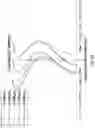
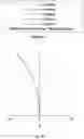
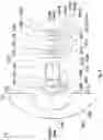
FIG. 1 is a schematic diagram illustrating the lens arrangement of a wide-angle lens assembly according to the first embodiment of the present disclosure.
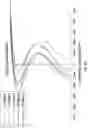
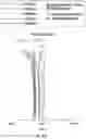
FIG. 2A is a schematic diagram illustrating the longitudinal aberration of the wide-angle lens assembly according to the first embodiment of the present disclosure.
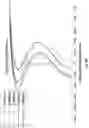
FIG. 2B is a schematic diagram illustrating the field curvature of the wide-angle lens assembly according to the first embodiment of the present disclosure.
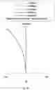
FIG. 2C is a schematic diagram illustrating the distortion of the wide-angle lens assembly according to the first embodiment of the present disclosure.
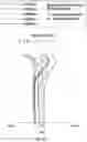
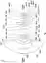
FIG. 3 is a schematic diagram illustrating the lens arrangement of a wide-angle lens assembly according to the second embodiment of the present disclosure.
FIG. 4A is a schematic diagram illustrating the longitudinal aberration of the wide-angle lens assembly according to the second embodiment of the present disclosure.
FIG. 4B is a schematic diagram illustrating the field curvature of the wide-angle lens assembly according to the second embodiment of the present disclosure.
FIG. 4C is a schematic diagram illustrating the distortion of the wide-angle lens assembly according to the second embodiment of the present disclosure.
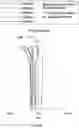
FIG. 5 is a schematic diagram illustrating the lens arrangement of a wide-angle lens assembly according to the third embodiment of the present disclosure.
FIG. 6A is a schematic diagram illustrating the longitudinal aberration of the wide-angle lens assembly according to the third embodiment of the present disclosure.
FIG. 6B is a schematic diagram illustrating the field curvature of the wide-angle lens assembly according to the third embodiment of the present disclosure.
FIG. 6C is a schematic diagram illustrating the distortion of the wide-angle lens assembly according to the third embodiment of the present disclosure.
DETAILED DESCRIPTION OF THE INVENTION
Please refer to FIG. 1. FIG. 1 is a schematic diagram illustrating the lens arrangement of a wide-angle lens assembly according to the first embodiment of the present disclosure. The wide-angle lens assembly 1 includes a first lens L11, a second lens L12, a third lens L13, a fourth lens L14, a fifth lens L15, an aperture stop ST1, a sixth lens L16, a seventh lens L17, an eighth lens L18, a ninth lens L19 and an optical filter OF1, and these elements are arranged in order from an object side to an image side along an optical axis OA1. During imaging, the light from the object side is imaged on an imaging surface IMA1.
The first lens L11 is a meniscus lens having negative refractive power and made of glass. The object-side surface S11 of the first lens L11 is a convex surface, and the image-side surface S12 of the first lens L11 is a concave surface. The object-side surface S11 and the image-side surface S12 are spherical surfaces.
The second lens L12 is a meniscus lens having negative refractive power and made of glass. The object-side surface S13 of the second lens L12 is a convex surface, and the image-side surface S14 of the second lens L12 is a concave surface. The object-side surface S13 and the image-side surface S14 are spherical surfaces.
The third lens L13 is a meniscus lens having negative refractive power and made of glass. The object-side surface S15 of the third lens L13 is a convex surface, and the image-side surface S16 of the third lens L13 is a concave surface. The object-side surface S15 and the image-side surface S16 are aspherical surfaces.
The fourth lens L14 is a biconcave lens having negative refractive power and made of glass. The object-side surface S17 of the fourth lens L14 is a concave surface, and the image-side surface S18 of the fourth lens L14 is a concave surface. The object-side surface S17 and the image-side surface S18 are spherical surfaces.
The fifth lens L15 is a biconvex lens having positive refractive power and made of glass. The object-side surface S18 of the fifth lens L15 is a convex surface, and the image-side surface S19 of the fifth lens L15 is a convex surface. The object-side surface S18 and the image-side surface S19 are spherical surfaces.
The fourth lens L14 and the fifth lens L15 are cemented together.
The sixth lens L16 is a biconvex lens having positive refractive power and made of glass. The object-side surface S111 of the sixth lens L16 is a convex surface, and the image-side surface S112 of the sixth lens L16 is a convex surface. The object-side surface S111 and the image-side surface S112 are aspherical surfaces.
The seventh lens L17 is a biconcave lens having negative refractive power and made of glass. The object-side surface S113 of the seventh lens L17 is a concave surface, and the image-side surface S114 of the seventh lens L17 is a concave surface. The object-side surface S113 and the image-side surface S114 are spherical surfaces.
The eighth lens L18 is a plano-convex lens having positive refractive power and made of glass. The object-side surface S114 of the eighth lens L18 is a convex surface, and the image-side surface S115 of the eighth lens L18 is a flat surface. The object-side surface S114 is a spherical surfaces.
The seventh lens L17 and the eighth lens L18 are cemented together.
The ninth lens L19 is a biconvex lens having positive refractive power and made of glass. The object-side surface S116 of the ninth lens L19 is a convex surface, and the image-side surface S117 of the ninth lens L19 is a convex surface. The object-side surface S116 and the image-side surface S117 are aspherical surfaces.
The object-side surface S118 and the image-side surface S119 of the optical filter OF1 are flat surfaces.
Furthermore, the wide-angle lens assembly 1 in the first embodiment satisfies one of the following conditions:
−15<f11/f1<−11. (1)
−10<f12/f1<−5. (2)
−5<f13/f1<−1. (3)
4.5<f19/f1<5.5 (4)
−1.5<f1123/f1<-: (5)
−2<f112345/f16789<-: (6)
0.8<TTL1/D11<1.2 (7)
wherein f11 is the focal length of the first lens L11, f12 is the focal length of the second lens L12, f13 is the focal length of the third lens L13, f19 is the focal length of the ninth lens L19, f1 is the effective focal length of the wide-angle lens assembly 1, f1123 is the effective focal length of the combination of the first lens L11, the second lens L12 and the third lens L13, f112345 is the effective focal length of the combination of the first lens L11, the second lens L12, the third lens L13, the fourth lens L14 and the fifth lens L15, f16789 is the effective focal length of the combination of the sixth lens L16, the seventh lens L17, the eighth lens L18 and the ninth lens L19, TTL1 is the distance between the object-side surface S11 of the first lens L11 and the imaging surface IMA1 along the optical axis OA1, and D11 is the effective diameter of the first lens L11.
Because of the disposition of the above lenses and the aperture stop ST1 and satisfying one of the conditions (1) to (7), the wide-angle lens assembly 1 may have a wider view angle, a minimized aperture value, a minimized total length and a minimized bore, and may also achieve the effective correction of aberration and be prevented from being effected by the variation in ambient temperature.
Table 1 illustrates the parameters of respective lenses in the wide-angle lens assembly 1 shown in FIG. 1. In Table 1, the effective focal length of the wide-angle lens assembly 1 is about 1.15 mm, the aperture value of the wide-angle lens assembly 1 is 2.0, the total length of the wide-angle lens assembly 1 is about 25.5 mm, and the view angle of the wide-angle lens assembly 1 is about 200 degrees.
| TABLE 1 | |||||
| Curvature | Abbe | ||||
| Surface | radius | Thickness | Refractive | No. | |
| # | (mm) | (mm) | index Nd | Vd | Note |
| S11 | 18.300 | 2.200 | 1.80 | 46.57 | First lens L11 |
| S12 | 6.880 | 3.070 | |||
| S13 | 8.750 | 0.950 | 1.80 | 46.57 | Second lens L12 |
| S14 | 3.790 | 2.000 | |||
| S15 | 6.470 | 0.500 | 1.75 | 45.43 | Third lens L13 |
| S16 | 1.836 | 1.680 | |||
| S17 | −51.090 | 0.500 | 1.80 | 46.57 | Fourth lens L14 |
| S18 | 10.100 | 4.400 | 1.85 | 23.79 | Fifth lens L15 |
| S19 | −7.020 | 1.730 | |||
| S110 | INF | −0.200 | Aperture stop ST1 | ||
| S111 | 3.720 | 1.210 | 1.61 | 57.54 | Sixth lens L16 |
| S112 | −5.310 | 0.410 | |||
| S113 | −16.360 | 0.500 | 1.85 | 23.79 | Seventh lens L17 |
| S114 | 2.470 | 1.790 | 1.60 | 65.46 | Eighth lens L18 |
| S115 | ∞ | 1.570 | |||
| S116 | 5.670 | 1.400 | 1.61 | 57.54 | Ninth lens L19 |
| S117 | −8.720 | 0.500 | |||
| S118 | ∞ | 0.700 | 1.52 | 64.21 | Optical filter OF1 |
| S119 | ∞ | 0.591 | |||
The respective sag value z of the respective aspherical surface of the respective aspherical lens in Table 1 along the optical axis OA1 is expressed by the following equation:
z=ch2/{1+[1−(k+1)c2h2]1/2}+Ah4+Bh6+Ch8+Dh10+Eh12+Fh14+Gh16
wherein c is the curvature of the surface, h is the distance between the optical axis and a point on the lens surface along a direction vertical to the optical axis, k is the conic coefficient, and A to G are the aspheric coefficients.
Table 2 illustrates the parameters of the respective aspherical surface of each lens listed in Table 2, wherein k is the conic constant, and A˜G are the aspheric coefficients.
| TABLE 2 | ||||||||
| Surface # | k | A | B | C | D | E | F | G |
| S15 | −9.35 | −1.77E−03 | −1.38E−04 | −1.23E−06 | 2.82E−06 | −1.58E−07 | 0.00E+00 | 0.00E+00 |
| S16 | −0.75 | −6.94E−04 | 2.10E−04 | −4.81E−05 | −3.26E−06 | 4.96E−06 | 0.00E+00 | 0.00E+00 |
| S111 | 1.28 | −1.51E−03 | −2.50E−04 | 2.95E−04 | 1.58E−05 | −2.30E−06 | 0.00E+00 | 0.00E+00 |
| S112 | −2.44 | 7.47E−03 | −7.88E−04 | 7.67E−04 | −1.39E−05 | −7.49E−07 | 0.00E+00 | 0.00E+00 |
| S116 | −0.24 | 1.60E−03 | −5.83E−05 | −4.59E−05 | −2.54E−06 | 1.54E−06 | −8.29E−07 | 8.60E−08 |
| S117 | 4.86 | 9.97E−03 | −5.63E−04 | 1.10E−05 | 4.20E−06 | −7.21E−06 | 7.84E−07 | 0.00E+00 |
Table 3 illustrates the parameters for the conditions (1) to (7) and the calculation results of the conditions (1) to (7). From Table 3, the wide-angle lens assembly 1 in the first embodiment can satisfy the conditions (1) to (7).
| TABLE 3 | |||||
| f11 | −14.93 mm | f12 | −9.05 mm | f13 | −3.56 mm |
| f19 | 5.86 mm | f1 | 1.15 mm | f1123 | −1.52 mm |
| f112345 | −7.07 mm | f16789 | 5.15 mm | TTL1 | 25.5 mm |
| D11 | 23.5 mm | ||||
| f11/f1 | −12.93 | f12/f1 | −7.84 | f13/f1 | −3.09 |
| f19/f1 | 5.07 | f1123/f1 | −1.32 | f112345/ | −1.37 |
| f16789 | |||||
| TTL1/D11 | 1.08 | ||||
Further, since sufficiently-strong refractive power may hardly be achieved if the calculation result of f11/f1 in the condition (1) is larger than −11.5, it would be better that the calculation result of f11/f1 is smaller than −11.5. Therefore, −15<f11/f1<−11. is a condition range that is capable of providing sufficiently-strong refractive power when it is satisfied.
Moreover, it can be known from FIG. 2A to FIG. 2C that the wide-angle lens assembly 1 in the first embodiment can achieve the required optical performance. FIG. 2A is a schematic diagram illustrating the longitudinal aberration of the wide-angle lens assembly 1 according to the first embodiment of the present disclosure. FIG. 2B is a schematic diagram illustrating the field curvature of the wide-angle lens assembly 1 according to the first embodiment of the present disclosure. FIG. 2C is a schematic diagram illustrating the distortion of the wide-angle lens assembly 1 according to the first embodiment of the present disclosure.
As shown in FIG. 2A, the longitudinal aberration amount in the wide-angle lens assembly 1 in the first embodiment ranges from −0.012 mm to 0.008 mm for the reference wavelengths of 0.438 μm, 0.486 μm, 0.546 μm, 0.587 μm and 0.656 μm.
As shown in FIG. 2B, the field curvature amount in the wide-angle lens assembly 1 in the first embodiment ranges from −12 μm to 12 μm in the tangential direction and the sagittal direction for the reference wavelengths of 0.438 μm, 0.486 μm, 0.546 μm, 0.587 μm and 0.656 μm.
As shown in FIG. 2C, the five lines almost overlap so that only one line is presented. The distortion amount in the wide-angle lens assembly 1 in the first embodiment ranges from −100% to 0% for the reference wavelengths of 0.438 μm, 0.486 μm, 0.546 μm, 0.587 μm and 0.656 μm.
Accordingly, it may be appreciated that the longitudinal aberration, the field curvature and the distortion of the wide-angle lens assembly 1 in the first embodiment can be efficiently corrected to achieve preferred optical performance.
Please refer to FIG. 3. FIG. 3 is a schematic diagram illustrating the lens arrangement of a wide-angle lens assembly according to the second embodiment of the present disclosure. The wide-angle lens assembly 2 includes a first lens L21, a second lens L22, a third lens L23, a fourth lens L24, a fifth lens L25, an aperture stop ST2, a sixth lens L26, a seventh lens L27, an eighth lens L28, a ninth lens L29 and an optical filter OF2, and these elements are arranged in order from an object side to an image side along an optical axis OA2. In operation, the light from the object side is imaged on an imaging surface IMA2.
The first lens L21 is a meniscus lens having negative refractive power and made of glass. The object-side surface S21 of the first lens L21 is a convex surface, and the image-side surface S22 of the first lens L21 is a concave surface. The object-side surface S21 and the image-side surface S22 are spherical surfaces.
The second lens L22 is a meniscus lens having negative refractive power and made of glass. The object-side surface S23 of the second lens L22 is a convex surface, and the image-side surface S24 of the second lens L22 is a concave surface. The object-side surface S23 and the image-side surface S24 are spherical surfaces.
The third lens L23 is a meniscus lens having negative refractive power and made of glass. The object-side surface S25 of the third lens L23 is a convex surface, and the image-side surface S26 of the third lens L23 is a concave surface. The object-side surface S25 and the image-side surface S26 are aspherical surfaces.
The fourth lens L24 is a biconcave lens having negative refractive power and made of glass. The object-side surface S27 of the fourth lens L24 is a concave surface, and the image-side surface S28 of the fourth lens L24 is a concave surface. The object-side surface S27 and the image-side surface S28 are spherical surfaces.
The fifth lens L25 is a biconvex lens having positive refractive power and made of glass. The object-side surface S28 of the fifth lens L25 is a convex surface, and the image-side surface S29 is a convex surface. The object-side surface S28 and the image-side surface S29 are spherical surfaces.
The fourth lens L24 and the fifth lens L25 are cemented together.
The sixth lens L26 is a biconvex lens having positive refractive power and made of glass. The object-side surface S211 of the sixth lens L26 is a convex surface, and the image-side surface S212 is a convex surface. The object-side surface S211 and the image-side surface S212 are aspherical surfaces.
The seventh lens L27 is a biconcave lens having negative refractive power and made of glass. The object-side surface S213 of the seventh lens L27 is a concave surface, and the image-side surface S214 is a concave surface. The object-side surface S213 and the image-side surface S214 are spherical surfaces.
The eighth lens L28 is a biconvex lens having positive refractive power and made of glass. The object-side surface S214 of the eighth lens L28 is a convex surface, and the image-side surface S215 of the eighth lens L28 is a convex surface. The object-side surface S214 and the image-side surface S215 are spherical surfaces.
The seventh lens L27 and the eighth lens L28 are cemented together.
The ninth lens L29 is a biconvex lens having positive refractive power and made of glass. The object-side surface S216 of the ninth lens L29 is a convex surface, and the image-side surface S217 is a convex surface. The object-side surface S216 and the image-side surface S217 are aspherical surfaces.
The object-side surface S218 and the image-side surface S219 of the optical filter OF2 are flat surfaces.
Furthermore, the wide-angle lens assembly 2 in the second embodiment satisfies one of the following conditions:
−15<f21/f2<−11. (8)
−10<f22/f2<−5. (9)
−5<f23/f2<−1. (10)
4.5<f29/f2<5.5 (11)
−1.5<f2123/f2<-: (12)
−2<f212345/f26789<-: (13)
0.8<TTL2/D21<1.2 (14)
wherein the definitions of f21, f22, f23, f29, f2, f2123, f212345, f26789, TTL2 and D21 are respectively the same as the definitions of f11, f12, f13, f19, f1, f1123, f112345, f16789, TTL1 and D11 in the first embodiment, and thus, the related descriptions will be omitted hereafter.
Because of the disposition of the above lenses and the aperture stop ST2 and satisfying one of the conditions (8) to (14), the wide-angle lens assembly 2 may have a wider view angle, a minimized aperture value, a minimized total length and a minimized bore, and may also achieve the effective correction of aberration and be prevented from being effected by the variation in ambient temperature.
Table 4 illustrates the parameters of each lens in the wide-angle lens assembly 2 shown in FIG. 3. Here, the effective focal length of the wide-angle lens assembly 2 is 1.04 mm, the aperture value of the wide-angle lens assembly 2 is 2.0, the total length of the wide-angle lens assembly 2 is 26.6 mm, and the view angle of the wide-angle lens assembly 2 is 202 degrees.
| TABLE 4 | |||||
| Curvature | Abbe | ||||
| Surface | radius | thickness | Refractive | No. | |
| # | (mm) | (mm) | index Nd | Vd | Note |
| S21 | 18.237 | 2.757 | 1.8 | 46.5 | First lens L21 |
| S22 | 6.487 | 3.420 | |||
| S23 | 9.090 | 1.167 | 1.8 | 46.5 | Second lens L22 |
| S24 | 3.696 | 2.064 | |||
| S25 | 6.480 | 0.470 | 1.74 | 44.9 | Third lens L23 |
| S26 | 1.849 | 1.643 | |||
| S27 | −41.487 | 0.489 | 1.8 | 46.5 | Fourth lens L24 |
| S28 | 8.541 | 4.499 | 1.85 | 23.8 | Fifth lens L25 |
| S29 | −7.057 | 1.804 | |||
| S210 | ∞ | −0.122 | Aperture stop ST2 | ||
| S211 | 3.703 | 1.191 | 1.61 | 57.5 | Sixth lens L26 |
| S212 | −5.267 | 0.404 | |||
| S213 | −16.240 | 0.469 | 1.85 | 23.8 | Seventh lens L27 |
| S214 | 2.468 | 1.535 | 1.6 | 65.5 | Eighth lens L28 |
| S215 | −81.056 | 1.626 | |||
| S216 | 5.444 | 1.461 | 1.61 | 58 | Ninth lens L29 |
| S217 | −8.526 | 0.500 | |||
| S218 | ∞ | 0.700 | 1.52 | 64.2 | Optical filter OF2 |
| S219 | ∞ | 0.518 | |||
The respective sag value z of the respective aspherical surface of the respective aspherical lens in Table 4 along the optical axis OA2 is expressed by the following equation:
z=ch2/{1+[1−(k+1)c2h2]1/2}+Ah4+Bh6+Ch8+Dh10+Eh12+Fh14+Gh16
wherein c is the curvature of the surface, h is the distance between the optical axis and a point on the lens surface along a direction vertical to the optical axis, k is the conic coefficient, and A to G are the aspheric coefficients.
Table 5 illustrates the parameters of the respective aspherical surface of the respective aspherical lens listed in Table 4, wherein k is a conic constant, and A to G are the aspheric coefficients.
| TABLE 5 | ||||||||
| Surface # | k | A | B | C | D | E | F | G |
| S25 | −15.54 | −1.07E−03 | −8.20E−05 | −6.88E−06 | 1.84E−06 | −7.76E−08 | 0.00E+00 | 0.00E+00 |
| S26 | −0.77 | −2.96E−03 | 9.37E−04 | −4.29E−05 | −1.53E−05 | 4.46E−06 | 0.00E+00 | 0.00E+00 |
| S211 | 1.18 | −2.19E−03 | −2.74E−05 | 3.44E−04 | −2.62E−06 | −3.34E−05 | 0.00E+00 | 0.00E+00 |
| S212 | −1.89 | 7.12E−03 | −6.49E−04 | 7.55E−04 | −1.05E−04 | 9.89E−06 | 0.00E+00 | 0.00E+00 |
| S216 | −0.81 | 1.08E−03 | −9.16E−05 | −1.03E−04 | −4.50E−06 | 1.81E−06 | −8.34E−07 | 5.42E−09 |
| S217 | 7.33 | 9.01E−03 | −7.59E−04 | −2.55E−05 | 3.83E−07 | −7.45E−06 | 7.77E−07 | 3.13E+09 |
Table 6 illustrates the parameters for the conditions (8) to (14) and the calculation results of the conditions (8) to (14). From Table 6, the wide-angle lens assembly 2 in the second embodiment can satisfy the conditions (8) to (14).
| TABLE 6 | |||||
| f21 | −13.91 mm | f22 | −8.53 mm | f23 | −3.62 mm |
| f29 | 5.66 mm | f2 | 1.04 mm | f2123 | −1.45 mm |
| f212345 | −6.44 mm | f26789 | 4.95 mm | TTL2 | 26.6 mm |
| D21 | 26 mm | ||||
| f21/f2 | −13.4 | f22/f2 | −8.22 | f23/f2 | −3.48 |
| f29/f2 | 5.45 | f2123/f2 | −1.40 | f212345/ | −1.30 |
| f26789 | |||||
| TTL2/D21 | 1.02 | ||||
Further, since sufficiently-strong refractive power may hardly be achieved if the calculation result of f22/f2 in the condition (9) is larger than −5.5, it would be better that the calculation result of f22/f2 is smaller than −5.5. Therefore, −10<f22/f2<−5. is a condition range that is capable of providing sufficiently-strong refractive power when it is satisfied.
Moreover, it can be known from FIG. 4A to FIG. 4C that the wide-angle lens assembly 2 in the second embodiment can achieve the required optical performance. FIG. 4A is a schematic diagram illustrating the longitudinal aberration of the wide-angle lens assembly 2 according to the second embodiment of the present disclosure. FIG. 4B is a schematic diagram illustrating the field curvature of the wide-angle lens assembly 2 according to the second embodiment of the present disclosure. FIG. 4C is a schematic diagram illustrating the distortion of the wide-angle lens assembly 2 according to the second embodiment of the present disclosure.
As shown in FIG. 4A, the longitudinal aberration amount in the wide-angle lens assembly 2 in the second embodiment ranges from −0.010 mm to 0.024 mm for the reference wavelengths of 0.438 μm, 0.486 μm, 0.546 μm, 0.587 μm and 0.656 μm.
As shown in FIG. 4B, the field curvature amount in the wide-angle lens assembly 2 in the second embodiment ranges from −14 μm to 5 μm in the tangential direction and the sagittal direction for the reference wavelengths of 0.438 μm, 0.486 μm, 0.546 μm, 0.587 μm and 0.656 μm.
As shown in FIG. 4C, the five lines almost overlap so that only one line is presented. The distortion amount in the wide-angle lens assembly 2 in the second embodiment ranges from −100% to 0% for the reference wavelengths 0.438 μm, 0.486 μm, 0.546 μm, 0.587 μm and 0.656 μm.
Accordingly, it may be appreciated that the longitudinal aberration, the field curvature and the distortion of the wide-angle lens assembly 2 in the second embodiment can be efficiently corrected to achieve preferred optical performance.
Please refer to FIG. 5. FIG. 5 is a schematic diagram illustrating the lens arrangement of a wide-angle lens assembly according to the third embodiment of the present disclosure. The wide-angle lens assembly 3 includes a first lens L31, a second lens L32, a third lens L33, a fourth lens L34, a fifth lens L35, an aperture stop ST3, a sixth lens L36, a seventh lens L37, an eighth lens L38, a ninth lens L39 and an optical filter OF3, and these elements are arranged in order from an object side to an image side along an optical axis OA3. In operation, the light from the object side is imaged on an imaging surface IMA3.
The first lens L31 is a meniscus lens having negative refractive power and made of glass. The object-side surface S31 of the first lens L31 is a convex surface, and the image-side surface S32 is a concave surface. The object-side surface S31 and the image-side surface S32 are spherical surfaces.
The second lens L32 is a meniscus lens having negative refractive power and made of glass. The object-side surface S33 of the second lens L32 is a convex surface, and the image-side surface S34 of the second lens L32 is a concave surface. The object-side surface S33 and the image-side surface S34 are spherical surfaces.
The third lens L33 is a meniscus lens having negative refractive power and made of glass. The object-side surface S35 of the third lens L33 is a convex surface, and the image-side surface S36 is a concave surface. The object-side surface S35 and the image-side surface S36 are aspherical surfaces.
The fourth lens L34 is a biconcave lens having negative refractive power and made of glass. The object-side surface S37 of the fourth lens L34 is a concave surface, and the image-side surface S38 is a concave surface. The object-side surface S37 and the image-side surface S38 are spherical surfaces.
The fifth lens L35 is a biconvex lens having positive refractive power and made of glass. The object-side surface S38 of the fifth lens L35 is a convex surface, and the image-side surface S39 of the fifth lens L35 is a convex surface. The object-side surface S38 and the image-side surface S39 are spherical surfaces.
The fourth lens L34 and the fifth lens L35 are cemented together.
The sixth lens L36 is a biconvex lens having positive refractive power and made of glass. The object-side surface S311 of the sixth lens L36 is a convex surface, and the image-side surface S312 is a convex surface. The object-side surface S311 and the image-side surface S312 are aspherical surfaces.
The seventh lens L37 is a biconcave lens having negative refractive power and made of glass. The object-side surface S313 of the seventh lens L37 is a concave surface, and the image-side surface S314 of the seventh lens L37 is a concave surface. The object-side surface S313 and the image-side surface S314 are spherical surfaces.
The eighth lens L38 is a biconvex lens having positive refractive power and made of glass. The object-side surface S314 of the eighth lens L38 is a convex surface, and the image-side surface S315 of the eighth lens L38 is a convex surface. The object-side surface S314 and the image-side surface S315 are spherical surfaces.
The seventh lens L37 and the eighth lens L38 are cemented together.
The ninth lens L39 is a biconvex lens having positive refractive power and made of glass. The object-side surface S316 of the ninth lens L39 is a convex surface, and the image-side surface S317 of the ninth lens L39 is a convex surface. The object-side surface S316 and the image-side surface S317 are aspherical surfaces.
The object-side surface S318 and the image-side surface S319 of the optical filter OF3 are flat surfaces.
Moreover, the wide-angle lens assembly 3 in the third embodiment satisfies one of the following conditions:
−15<f31/f3<−11. (15)
−10<f32/f3<5. (16)
−5<f33/f3<−1. (17)
4.5<f39/f3<5.5 (18)
−1.5<f3123/f3<-: (19)
−2<f312345/f36789<-: (20)
0.8<TTL3/D31<1.2 (21)
wherein the definitions of f31, f32, f33, f39, f3, f3123, f312345, f36789, TTL3 and D31 are respectively the same as the definitions of f11, f12, f13, f19, f1, f1123, f112345, f16789, TTL1 and D11 in the first embodiment, and thus, the related descriptions will be omitted hereafter.
Because of the disposition of the above lenses and the aperture stop ST3 and satisfying one of the conditions (15) to (21), the wide-angle lens assembly 3 may have a wider view angle, a minimized aperture value, a minimized total length and a minimized bore, and may also achieve the effective correction of aberration and be prevented from being effected by the variation in ambient temperature.
Table 7 illustrates the parameters of each lens in the wide-angle lens assembly 3 shown in FIG. 5. Here, the effective focal length of the wide-angle lens assembly 3 is 1.00 mm, the aperture value of the wide-angle lens assembly 3 is 2.0, the total length of the wide-angle lens assembly 3 is 25.7 mm, and the view angle of the wide-angle lens assembly 3 is 201 degrees.
| TABLE 7 | |||||
| Curvature | Abbe | ||||
| Surface | radius | thickness | Refractive | No. | |
| # | (mm) | (mm) | index Nd | Vd | Note |
| S31 | 17.137 | 2.497 | 1.83 | 42.7 | First lens L31 |
| S32 | 6.336 | 4.402 | |||
| S33 | 8.375 | 0.647 | 1.8 | 46.6 | Second lens L32 |
| S34 | 3.367 | 1.617 | |||
| S35 | 6.418 | 0.300 | 1.73 | 54.7 | Third lens L33 |
| S36 | 1.853 | 1.573 | |||
| S37 | −30.930 | 0.390 | 1.8 | 46.6 | Fourth lens L34 |
| S38 | 9.325 | 4.496 | 1.92 | 24 | Fifth lens L35 |
| S39 | −7.401 | 1.729 | |||
| S310 | ∞ | −0.162 | Aperture stop ST3 | ||
| S311 | 3.630 | 1.187 | 1.61 | 57.5 | Sixth lens L36 |
| S312 | −5.380 | 0.391 | |||
| S313 | −16.702 | 0.410 | 1.85 | 23.8 | Seventh lens L37 |
| S314 | 2.388 | 1.463 | 1.62 | 63.4 | Eighth lens L38 |
| S315 | −93.248 | 1.603 | |||
| S316 | 5.036 | 1.480 | 1.62 | 58.1 | Ninth lens L39 |
| S317 | −9.341 | 0.500 | |||
| S318 | ∞ | 0.700 | 1.52 | 64.2 | Optical filter OF3 |
| S319 | ∞ | 0.481 | |||
The respective sag value z of the respective aspherical surface of the respective aspherical lens in Table 7 along the optical axis OA3 is expressed by the following equation:
z=ch2/{1+[1−(k+1)c2h2]1/2}+Ah4+Bh6+Ch8+Dh10+Eh12+Fh14+Gh16
wherein c is the curvature of the surface, h is the distance between the optical axis and a point on the lens surface along a direction vertical to the optical axis, k is the conic coefficient, and A to G are the aspheric coefficients.
Table 8 illustrates the parameters of the aspherical surface of the respective aspherical lens listed in Table 7, wherein k is the conic constant, and A to G are the aspheric coefficients.
| TABLE 8 | ||||||||
| Surface # | k | A | B | C | D | E | F | G |
| S35 | −17.84 | −1.38E−03 | −7.27E−05 | −7.16E−06 | 1.68E−06 | −4.53E−08 | 0.00E+00 | 0.00E+00 |
| S36 | −0.77 | −3.49E−03 | 1.21E−03 | −5.73E−05 | −2.04E−05 | 5.09E−06 | 0.00E+00 | 0.00E+00 |
| S311 | 1.22 | −2.15E−03 | 1.77E−04 | 4.10E−04 | −7.32E−07 | −5.03E−05 | 0.00E+00 | 0.00E+00 |
| S312 | −2.20 | 7.38E−03 | −3.91E−04 | 8.66E−04 | −1.08E−04 | 8.27E−06 | 0.00E+00 | 0.00E+00 |
| S316 | −1.38 | 5.33E−04 | −1.96E−04 | −1.14E−04 | −5.09E−06 | 1.88E−06 | −8.35E−07 | −2.14E−08 |
| S317 | 9.91 | 7.18E−03 | −8.83E−04 | −3.06E−05 | 1.47E−06 | −7.15E−06 | 8.01E−07 | −4.71E+09 |
Table 9 illustrates the parameters for the conditions (15) to (21) and the calculation results of the conditions (15) to (21). From Table 9, the wide-angle lens assembly 3 in the third embodiment can satisfy the conditions (15) to (21).
| TABLE 9 | |||||
| f31 | −13.39 mm | f32 | −7.39 mm | f33 | −3.66 mm |
| f39 | 5.45 mm | f3 | 1.00 mm | f3123 | −1.39 mm |
| f312345 | −6.22 mm | f36789 | 4.76 mm | TTL3 | 25.7 mm |
| D31 | 25.0 mm | ||||
| f31/f3 | −13.40 | f32/f3 | −7.40 | f33/f3 | −3.66 |
| f39/f3 | 5.45 | f3123/f3 | −1.39 | f312345/ | −1.31 |
| f36789 | |||||
| TTL3/D31 | 1.03 | ||||
Further, since sufficiently-strong refractive power may hardly be achieved if the calculation result of f33/f3 in the condition (17) is larger than −1.5, it would be better that the calculation result of f33/f3 is smaller than −1.5. Therefore, −5<f33/f3<−1. is a condition range that is capable of providing sufficiently-strong refractive power when it is satisfied.
Moreover, it can be known from FIG. 6A to FIG. 6C that the wide-angle lens assembly 3 in the third embodiment can achieve the required optical performance. FIG. 6A is a schematic diagram illustrating the longitudinal aberration of the wide-angle lens assembly 3 according to the third embodiment of the present disclosure. FIG. 6B is a schematic diagram illustrating the field curvature of the wide-angle lens assembly 3 according to the third embodiment of the present disclosure. FIG. 6C is a schematic diagram illustrating the distortion of the wide-angle lens assembly 3 according to the third embodiment of the present disclosure.
As shown in FIG. 6A, the longitudinal aberration amount in the wide-angle lens assembly 3 in the third embodiment ranges from −0.010 mm to 0.023 mm for the reference wavelengths of 0.438 μm, 0.486 μm, 0.546 μm, 0.587 μm and 0.656 μm.
As shown in FIG. 6B, the tangential direction and the sagittal direction the field curvature amount in the wide-angle lens assembly 3 in the third embodiment ranges from −14 μm to 3 μm for the reference wavelengths of 0.438 μm, 0.486 μm, 0.546 μm, 0.587 μm and 0.656 μm.
As shown in FIG. 6C, the five lines almost overlap so that only one line is presented. The distortion amount in the wide-angle lens assembly 3 in the third embodiment ranges from −100% to 0% for the reference wavelengths 0.438 μm, 0.486 μm, 0.546 μm, 0.587 μm and 0.656 μm.
Accordingly, it may be appreciated that the longitudinal aberration, the field curvature and the distortion of the wide-angle lens assembly 3 in the third embodiment can be efficiently corrected to achieve preferred optical performance.
Even though the primary conditions to be satisfied in the present disclosure are −15<f1/f<−11, −10<f2/f<−5. and −5<f3/f<−1, this embodiment also satisfies the other conditions. The sufficiently-strong refractive power may be achieved when the conditions −15<f1/f<−11, −10<f2/f<−5. and −5<f3/f<−1. are satisfied.
It should be understood that although the present disclosure has been described with reference to the above preferred embodiments, these embodiments are not intended to retrain the present disclosure. It will be apparent to one of ordinary skill in the art that various changes or modifications to the described embodiments can be made without departing from the spirit of the present disclosure. Accordingly, the scope of the present disclosure is defined by the attached claims.
Claims
What is claimed is:1. A wide-angle lens assembly, comprising:
a first lens having negative refractive power, and the first lens comprising a concave surface facing an image side;
a second lens having negative refractive power, and the second lens comprising a concave surface facing the image side;
a third lens having negative refractive power, and the third lens comprising a concave surface facing the image side;
a fourth lens having refractive power;
a fifth lens having refractive power;
a sixth lens having positive refractive power, and the sixth lens being a biconvex lens;
a seventh lens having refractive power;
an eighth lens having refractive power; and
a ninth lens having positive refractive power, and the ninth lens being a biconvex lens;
wherein the wide-angle lens assembly satisfies:
0.8<TTL/D1<1.2;
wherein TTL is a distance between an object-side surface of the first lens and an imaging surface along the optical axis, and D1 is an effective diameter of the first lens; and
wherein the first lens, the second lens, the third lens, the fourth lens, the fifth lens, the sixth lens, the seventh lens, the eighth lens and the ninth lens are arranged in order from an object side to the image side along an optical axis.
2. The wide-angle lens assembly as claimed in claim 1, wherein the wide-angle lens assembly further satisfies:
−15<f1/f<−11;
wherein f1 is a focal length of the first lens, and f is an effective focal length of the wide-angle lens assembly.
3. The wide-angle lens assembly as claimed in claim 2, wherein the wide-angle lens assembly further satisfies:
10<f2/f<−5;
wherein f2 is a focal length of the second lens, and f is an effective focal length of the wide-angle lens assembly.
4. The wide-angle lens assembly as claimed in claim 3, wherein the wide-angle lens assembly further satisfies:
−5<f3/f<−1;
wherein f3 is a focal length of the third lens, and f is an effective focal length of the wide-angle lens assembly.
5. The wide-angle lens assembly as claimed in claim 4, wherein the wide-angle lens assembly further satisfies:
−1.5<f123/f<-;
wherein f123 is an effective focal length of a combination of the first lens, the second lens and the third lens, and f is an effective focal length of the wide-angle lens assembly.
6. The wide-angle lens assembly as claimed in claim 1, wherein the wide-angle lens assembly further satisfies:
4.5<f9/f<5.5;
wherein f9 is a focal length of the ninth lens, and f is an effective focal length of the wide-angle lens assembly.
7. The wide-angle lens assembly as claimed in claim 1, wherein the wide-angle lens assembly further satisfies:
−2<f12345/f6789<-;
wherein f12345 is an effective focal length of a combination of the first lens, the second lens, the third lens, the fourth lens and the fifth lens, and f6789 is an effective focal length of a combination of the sixth lens, the seventh lens, the eighth lens and the ninth lens.
8. The wide-angle lens assembly as claimed in claim 1, wherein the fourth lens and the fifth lens are cemented together.
9. The wide-angle lens assembly as claimed in claim 1, wherein the seventh lens and the eighth lens are cemented together.
10. The wide-angle lens assembly as claimed in claim 1, wherein the eighth lens further comprises a flat surface facing the image side.
11. The wide-angle lens assembly as claimed in claim 1, wherein the third lens, the sixth lens and the ninth lens are aspheric lenses.
12. A wide-angle lens assembly, comprising:
a first lens having negative refractive power, and the first lens comprising a concave surface facing an image side;
a second lens having negative refractive power, and the second lens comprising a concave surface facing the image side;
a third lens having negative refractive power, and the third lens comprising a concave surface facing the image side;
a fourth lens having refractive power;
a fifth lens having refractive power;
a sixth lens having positive refractive power, and the sixth lens being a biconvex lens;
a seventh lens having refractive power;
an eighth lens having refractive power; and
a ninth lens having positive refractive power, and the ninth lens being a biconvex lens;
wherein the wide-angle lens assembly satisfies:
−1.5<f123/f<-;
wherein f123 is an effective focal length of a combination of the first lens, the second lens and the third lens, and f is an effective focal length of the wide-angle lens assembly; and
wherein the first lens, the second lens, the third lens, the fourth lens, the fifth lens, the sixth lens, the seventh lens, the eighth lens and the ninth lens are arranged in order from an object side to the image side along an optical axis.
13. The wide-angle lens assembly as claimed in claim 12, wherein the wide-angle lens assembly further satisfies:
−15<f1/f<−11;
4.5<f9/f<5.5;
wherein f1 is a focal length of the first lens, f9 is a focal length of the ninth lens, and f is an effective focal length of the wide-angle lens assembly.
14. The wide-angle lens assembly as claimed in claim 13, wherein the wide-angle lens assembly further satisfies:
−10<f2/f<−5;
wherein f2 is a focal length of the second lens, and f is an effective focal length of the wide-angle lens assembly.
15. The wide-angle lens assembly as claimed in claim 14, wherein the wide-angle lens assembly further satisfies:
−5<f3/f<−1;
wherein f3 is a focal length of the third lens, and f is an effective focal length of the wide-angle lens assembly.
16. The wide-angle lens assembly as claimed in claim 12, wherein the wide-angle lens assembly further satisfies:
0.8<TTL/D1<1.2;
wherein TTL is a distance between an object-side surface of the first lens and an imaging surface along the optical axis, and D1 is an effective diameter of the first lens.
17. The wide-angle lens assembly as claimed in claim 12, wherein the wide-angle lens assembly further satisfies:
−2<f12345/f6789<-;
wherein f12345 is an effective focal length of a combination of the first lens, the second lens, the third lens, the fourth lens and the fifth lens, and f6789 is an effective focal length of a combination of the sixth lens, the seventh lens, the eighth lens and the ninth lens.
18. The wide-angle lens assembly as claimed in claim 12, wherein the fourth lens and the fifth lens are cemented together, and the seventh lens and the eighth lens are cemented together.
19. The wide-angle lens assembly as claimed in claim 12, wherein the eighth lens further comprises a flat surface facing the image side.
20. The wide-angle lens assembly as claimed in claim 12, wherein the third lens, the sixth lens and the ninth lens are aspheric lenses.
Images & Drawings included:

Sources:
- United States Patent and Trademark Office - verify current appl. status at the USPTO↗
Similar patent applications:
- » 20180335611
Wide-angle lens assembly - » 20190219798
Wide-angle lens assembly - » 20170315330
Wide-angle lens assembly - » 20180329183
Wide-angle lens assembly - » 20190033561
Wide-angle lens assembly - » 20190121106
Wide-angle lens assembly and imaging device - » 20150277088
Wide-angle lens assembly - » 20170052349
WIDE-ANGLE LENS ASSEMBLY - » 20180329177
Wide-angle lens assembly - » 20190339490
Wide-angle lens assembly
Recent applications in this class:
- » 20250291156 2025-09-18
OPTICAL IMAGING SYSTEM - » 20250291155 2025-09-18
OPTICAL IMAGING SYSTEM - » 20250284094 2025-09-11
OPTICAL IMAGING SYSTEM - » 20250284093 2025-09-11
HIGH BRIGHTNESS ZOOM PROJECTION LENS - » 20250271640 2025-08-28
OPTICAL IMAGING SYSTEM - » 20250271639 2025-08-28
OPTICAL SYSTEM INCLUDING NEGATIVE LENS AND POSITIVE LENS, IMAGING APPARATUS INCLUDING THE SAME, IN-VEHICLE SYSTEM INCLUDING THE SAME, AND MOVING APPARATUS INCLUDING THE SAME - » 20250271638 2025-08-28
PORTABLE ELECTRONIC DEVICE, OPTICAL IMAGING SYSTEM, AND LENS ASSEMBLY - » 20250271637 2025-08-28
IMAGING LENS AND IMAGING APPARATUS - » 20250264692 2025-08-21
INFORMATION HANDLING SYSTEM CAMERA LENS WITH EIGHT ELEMENTS FOR IMPROVED APERTURE AND REDUCED BLUR - » 20250258358 2025-08-14
OPTICAL IMAGING LENS
Recent applications for this Assignee:
- » 20240361104 2024-10-31
AIMING DEVICES AND METHODS THEREOF - » 20240361104 2024-10-31
AIMING DEVICES AND METHODS THEREOF - » 20230288683 2023-09-14
Optical system - » 20230288683 2023-09-14
Optical system - » 20230194256 2023-06-22
Range finder and lens assembly for display thereof - » 20230194256 2023-06-22
Range finder and lens assembly for display thereof - » 20230047206 2023-02-16
Lens device capable of operation of multi-magnifications, optical zoom in high magnification, and miniaturization of the lens module thereof - » 20230047206 2023-02-16
Lens device capable of operation of multi-magnifications, optical zoom in high magnification, and miniaturization of the lens module thereof - » 20230018568 2023-01-19
Lens Device - » 20230018568 2023-01-19
Lens Device