Projection lens structure
US20200073216A1
2020-03-05
16/121,870
2018-09-05
✅ Patent granted
US 10,606,154 B2
2020-03-31
-
-
Jerry L Brooks
Rosenberg, Klein & Lee
2038-09-22
Abstract:
A projection lens structure includes a first group of lens, an aperture stop and a second group of lend. The aperture stop is arranged at a rear of the first group of lens to form a long-focus lens with a focal length between 30-80 mm and the second group of lens is arranged at a rear of the aperture stop to form a short-focus lens with a focal length between 20-30 mm. With the long-focus lens and the short-focus lens operated correspondingly, the structure of the projection lens is simple and the manufacturing cost is low without affecting the quality of produced images.
Inventors:
- SHENG-CHE WU 10 🇹🇼 TAOYUAN CITY, Taiwan
- YU-HUNG CHOU 7 🇹🇼 TAOYUAN CITY, Taiwan
- YOU-DA CHEN 2 🇹🇼 TAOYUAN CITY, Taiwan
- Sheng-Che Wu 5 🇹🇼 Taoyuan, Taiwan
- Yu-Hung Chou 5 🇹🇼 Taoyuan, Taiwan
- You-Da Chen 2 🇹🇼 Taoyuan, Taiwan
Assignee:
- Sun Yang Optics Development Co., Ltd. 5 🇹🇼 Taoyuan, Taiwan
Applicant:
Interested in similar patents?
Get notified when new applications in this technology area are published.
Classification:
G03B21/147 » CPC main
Projectors or projection-type viewers; Accessories therefor; Details Optical correction of image distortions, e.g. keystone
G02B27/0037 » CPC further
Optical systems or apparatus not provided for by any of the groups - for optical correction, e.g. distorsion, aberration with diffracting elements
G02B27/0955 » CPC further
Optical systems or apparatus not provided for by any of the groups -; Beam shaping, e.g. changing the cross-sectional area, not otherwise provided for; Using specific optical elements; Refractive optical elements Lenses
G02B27/00 IPC
Optical systems or apparatus not provided for by any of the groups -
G03B21/14 IPC
Projectors or projection-type viewers; Accessories therefor Details
G02B27/09 IPC
Optical systems or apparatus not provided for by any of the groups - Beam shaping, e.g. changing the cross-sectional area, not otherwise provided for
H04N9/31 » CPC further
Details of colour television systems; Picture reproducers Projection devices for colour picture display, e.g. using electronic spatial light modulators [ESLM]
G02B7/04 » CPC further
Mountings, adjusting means, or light-tight connections, for optical elements for lenses with mechanism for focusing or varying magnification
G02B9/64 » CPC further
Optical objectives characterised both by the number of the components and their arrangements according to their sign, i.e. + or - having more than six components
Description
BACKGROUND OF THE INVENTION
1. Field of the Invention
The present invention relates to a projection lens structure, particularly to one that has a long-focus lens and a short-focus lens operated together to manufacture the projection lens with simple structure and low costs.
2. Description of the Related Art
As technologies developed, applications of projectors have been expanded from presentations in the offices to video co mmunications and TV programs displays in household families, and the volume of the projectors is more and more important when it comes to easy carrying for use. Therefore, simpler structures and less manufacturing cost come together as the volume of projectors are reduced. However, the quality of the projected images is also reduced as well.
In view of the quality of the projected images, the longer the focal lengths are, the narrower the angle of the field of view the projectors have, and as the focal lengths become shorter, the distortion of the images gets worse. So it is impossible to guarantee the quality of the images with the focal lengths reduced. Therefore, it is desirable to make an arrangement of the structures of the projectors to achieve greater efficiency in projections by adjustment of the focal lengths while ensuring the quality of the projected images.
SUMMARY OF THE INVENTION
A primary objective of the present invention is to provide a projection lens structure that has a short-focus lens and a long-focus lens coordinated in operation to produce images with fine quality by a simple structure and low manufacturing cost.
Another objective of the present invention is to provide a projection lens structure that has a short-focus lens and a long-focus lens operated correspondingly with a large aperture stop to enhance quality of the images.
To achieve the objectives mentioned above, the present invention comprises a first group of lens; an aperture stop arranged at a rear side of said first group of lens, forming a long-focus lens with a focal length between 30˜80 mm; and a second group of lens arranged at a rear side of said aperture stop, forming a short-focus lens with a focal length between 20˜30 mm.
Furthermore, the first group of lens includes a first lens, a second lens, a third lens and a fourth lens, among which the second and fourth lenses are plastic aspheric lenses. The second lens is a negative meniscus lens with a focal length between −20˜−50 mm or a focal length between −25˜−40 mm. The fourth lens is a meniscus lens with a focal length longer than 300 mm when being positive or shorter than −300 mm when being negative. The first lens has an abbe number greater than 60.
In addition, the second group of lens includes at least one triplet lens having dioptric values arranged as positive-negative-positive or negative-positive-negative and the triplet lens further includes a fifth lens, a sixth lens and a seventh lens. The second group of lens further includes an eighth lens arranged at a rear side of the triplet lens, and at least two of the fifth, sixth, seventh and eighth lens have an abbe number greater than 60.
Moreover, the second group lens further includes a last lens with an abbe number less than 25. The aperture stop has an f-number between 1.6˜2.0.
The first group of lens includes a first lens, a second lens, a third lens and a fourth lens among which the second and third lenses are plastic aspheric lenses; the third lens is a meniscus lens with a focal length longer than 300 mm when being positive or shorter than −300 mm when being negative.
Still, to achieve the objectives, another structure of the present invention comprises a first group of lens including a first lens, a second lens, a third lens and a fourth lens, said second being negative and being a plastic aspheric lens in a meniscus shape with a focal length between −25˜−50 mm; an aperture stop having an f-number between 1.6˜2.0 and arranged at a rear side of said first group of lens, forming a long-focus lens with a focal length between 30˜80 mm; and a second group of lens including at least one triplet lens, an eighth lens and a last lens and arranged at a rear side of said aperture stop, forming a short-focus lens with a focal length between 20˜30 mm, said triplet lens having dioptric values arranged as positive-negative-positive or negative-positive-negative and including a fifth lens, a sixth lens and a seventh lens, at least two of the fifth, sixth, seventh and eighth lens having an abbe number greater than 60 and said last lens having an abbe number less than 25.
With structures disclosed above, the present invention has the short-focus lens and long-focus lens operated correspondingly to manufacture a projection lens with simple structure and low cost; meanwhile, the quality of produced images can also be enhanced with the aperture stop arranged between the long-focus lens and the short-focus lens.
BRIEF DESCRIPTION OF THE DRAWINGS
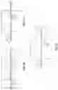
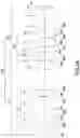
FIG. 1A is a schematic diagram illustrating lenses arrangement of the present invention in a first embodiment;
FIG. 1B is a transverse ray fan plot with an image height of 0.0000 mm according to the present invention in the first embodiment;
FIG. 1C is a transverse ray fan plot with an image height of 5.4620 mm according to the present invention in the first embodiment;
FIG. 1D is a transverse ray fan plot with an image height of 7.8030 mm according to the present invention in the first embodiment;
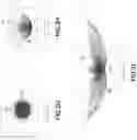
FIG. 1E is a field curvature diagram of the present invention in the first embodiment;
FIG. 1F is a distortion diagram of the present invention in the first embodiment;
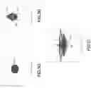
FIG. 1G is a spot diagram with an image height of 0.000 mm according to the present invention in the first embodiment;
FIG. 1H is a spot diagram with an image height of 5.462 mm according to the present invention in the first embodiment;
FIG. 1I is a spot diagram with an image height of 7.804 mm according to the present invention in the first embodiment;
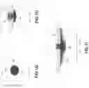
FIG. 2A is a schematic diagram illustrating lenses arrangement of the present invention in a second embodiment;
FIG. 2B is a transverse ray fan plot with an image height of 0.0000 mm according to the present invention in the second embodiment;
FIG. 2C is a transverse ray fan plot with an image height of 5.4620 mm according to the present invention in the second embodiment;
FIG. 2D is a transverse ray fan plot with an image height of 7.8030 mm according to the present invention in the second embodiment;
FIG. 2E is a field curvature diagram of the present invention in the second embodiment;
FIG. 2F is a distortion diagram of the present invention in the second embodiment;
FIG. 2G is a spot diagram with an image height of 0.000 mm according to the present invention in the second embodiment;
FIG. 2H is a spot diagram with an image height of 5.462 mm according to the present invention in the second embodiment;
FIG. 2I is a spot diagram with an image height of 7.804 mm according to the present invention in the second embodiment;
FIG. 3A is a schematic diagram illustrating lenses arrangement of the present invention in a third embodiment;
FIG. 3B is a transverse ray fan plot with an image height of 0.0000 mm according to the present invention in the third embodiment;
FIG. 3C is a transverse ray fan plot with an image height of 5.4620 mm according to the present invention in the third embodiment;
FIG. 3D is a transverse ray fan plot with an image height of 7.8030 mm according to the present invention in the third embodiment;
FIG. 3E is a field curvature diagram of the present invention in the third embodiment;
FIG. 3F is a distortion diagram of the present invention in the third embodiment;
FIG. 3G is a spot diagram with an image height of 0.000 mm according to the present invention in the third embodiment;
FIG. 3H is a spot diagram with an image height of 5.463 mm according to the present invention in the third embodiment; and
FIG. 3I is a spot diagram with an image height of 7.804 mm according to the present invention in the third embodiment.
DETAILED DESCRIPTION OF THE PREFERRED EMBODIMENT
In FIGS. 1A-3I, there are three embodiments of the present invention. In the embodiments, a projection lens structure mainly comprises a first group of lens G1, an aperture stop S, a second group of lens G2.
The first group of lens G1 includes a first lens L1, a second lens L2, a third lens L3 and a fourth lens L4. The second lens L2 is a negative meniscus lens with a focal length between −20˜−50 mm, or a focal length between −25˜−40 mm in another preferred embodiment.
The aperture stop S has an f-number between 1.6˜2.0 and is arranged at a rear side of the first group of lens G1, forming a long-focus lens 10 from the first group of lens G1 to the aperture stop S with a focal length between 30˜80 mm; in other words, the long-focus lens 10 is near the projection screen in operation.
The second group of lens G2 includes at least one triplet lens C, an eighth lens L8 and a last lens L9. The triplet lens C has dioptric values arranged as positive-negative-positive or negative-positive-negative and includes a fifth lens L5, a sixth lens L6 and a seventh lens L7, at least two of which have an abbe number greater than 60, and the last lens L9 has an abbe number less than 25. The second group of lens G2 is arranged at a rear side of the aperture stop S, forming a short-focus lens 20 from the aperture stop S to the second group of lens G2 with a focal length between 20˜30 mm.
Furthermore, a transmissive smooth picture actuator P is disposed at a rear side of the last lens L9. The transmissive smooth picture actuator P is a glass tablet device which is able to rotate rapidly to enhance the resolution by image-shifts. In this way, an image with 1080P resolution can be enhanced to 4K2K resolution. An optical element E is disposed at a rear of the transmissive smooth picture actuator P. In this embodiment, the optical element E is a prism, and a cover glass and an image IMA of a digital micromirror device 30 are disposed behind the prism; but the present invention is not limited to this application. The structures above are common features shared in the three embodiments.
Further referring to FIG. 1A, in the first embodiment the first lens L1, the second lens L2, the third lens L3, the fourth lens L4, the fifth lens L5, a sixth lens L6, a seventh lens L7, the eighth lens L8 and the last lens L9 of the projection lens 30A each has a radius on each surface, a thickness, refraction rate and an abbe number according to the following specification:
| Abbe | ||||
| Surface no. | Radius (mm) | Thickness (mm) | Refraction rate | number |
| 1R1 | 48.65 | 1.60 | 1.62 | 63.4 |
| 1R2 | 16.83 | |||
| 2R1 | 15.81 | 3.00 | 1.53 | 56.3 |
| 2R2 | 8.29 | |||
| 3R1 | 79.46 | 4.39 | 1.77 | 49.6 |
| 3R2 | −42.14 | |||
| 4R1 | 19.89 | 6.50 | 1.53 | 56.3 |
| 4R2 | 17.22 | |||
| S | Infinity | |||
| 5R1 | Infinity | 1.00 | 1.72 | 29.5 |
| 6R1 | 18.64 | 8.57 | 1.49 | 81.6 |
| 7R1 | −13.06 | 1.58 | 1.72 | 29.5 |
| 7R2 | −31.30 | |||
| 8R1 | 47.77 | 5.33 | 1.49 | 81.6 |
| 8R2 | −30.56 | |||
| 9R1 | 40.40 | 5.80 | 1.92 | 18.90 |
| 9R2 | 110.92 | |||
In the table above, the 1R1 is the projecting surface of the first lens L1 and the 1R2 is the image inputting surface of the first lens L1. The 2R1 is the projecting surface of the second lens L2 and the 2R2 is the image inputting surface of the second lens L2. The 3R1 is the projecting surface of the third lens L3 and the 3R2 is the image inputting surface of the third lens L3. The 4R1 is the projecting surface of the fourth lens L4 and the 4R2 is the image inputting surface of the fourth lens L4. The 5R1 is the projecting surface of the fifth lens L5. The 6R1 is the projecting surface of the sixth lens L6. The 7R1 is the projecting surface of the seventh lens L7 and the 7R2 is the image inputting surface of the seventh lens L7. The 8R1 is the projecting surface of the eighth lens L8 and the 8R2 is the image inputting surface of the eighth lens L8. The 9R1 is the projecting surface of the last lens L9 and the 9R2 is the image inputting surface of the last lens L9.
In addition, the following table displays the radius, the conic value and order aspheric coefficients of the projecting surface 2R1 and the image inputting surface 2R2 of the second lens L2 as a plastic aspheric lens.
| Aspheric lens | 2R1 | 2R2 | |
| Radius | 15.81 | 8.29 | |
| Conic | — | −0.83 | |
| 4th | −1.57E−04 | −2.03E−04 | |
| 6th | 5.84E−07 | 7.29E−07 | |
| 8th | −3.41E−09 | −4.44E−09 | |
| 10th | 1.08E−11 | 1.33E−11 | |
| 12th | −2.20E−14 | −1.55E−14 | |
In addition, the following table displays the radius, the conic value and order aspheric coefficients of the projecting surface 4R1 and the image inputting surface 4R2 of the fourth lens L4 as a plastic aspheric lens.
| Aspheric lens | 4R1 | 4R2 | |
| Radius | 19.89 | 17.22 | |
| Conic | 0.04 | 0.98 | |
| 4th | −8.38E−06 | −3.31E−05 | |
| 6th | −2.36E−08 | −1.71E−07 | |
| 8th | −4.08E−10 | −2.00E−09 | |
| 10th | 2.07E−14 | 1.32E−11 | |
| 12th | −8.06E−15 | −1.29E−13 | |
In this embodiment, the fourth lens L4 is a meniscus lens with a focal length longer than 300 mm when being positive or shorter than −300 mm when being negative, and the first lens L1 has an abbe number greater than 60. But the present invention is not limited to such application.
With structures disclosed above, the projection lens 30A has a first wavelength λ1 set as 0.460 um, a second wavelength λ2 set as 0.545 um and a third wavelength λ3 set as 0.620 um; thereby it is able to simulate different transverse ray fan plots as shown in FIGS. 1B-1D and to display images with respective image heights of 0.0000 mm, 5.4620 mm and 7.8030 mm on the image IMA. The transverse aberration of a Y-axis is represented by ey. The pupil height of the Y-axis is represented by py. The transverse aberration of an X-axis is represented by ex. The pupil height of the X-axis is represented by px. The maximum of the transverse aberration of the X-axis and the Y-axis is ±20.000 um and the pupil heights of the X-axis and the Y-axis are in normalized proportion; a maximum field of FIGS. 1E and 1F is 31.786°. FIGS. 1G, 1H and 1I are spot diagrams with different image heights displayed on the image IMA. When the image height is 0.000 mm, the root mean square radius is 2.578 um and the geo radius is 5.051 um. When the image height is 5.462 mm, the root mean square radius is 2.636 um and the geo radius is 12.865 um. When the image height is 7.804 mm, the root mean square radius is 4.563 um and the geo radius is 22.942 um. From the data above we can learn that the projection lens 30A has a simple structure and requires low costs for manufacturing with fine image quality.
Further referring to FIG. 2A, in the first embodiment the first lens L1, the second lens L2, the third lens L3, the fourth lens L4, the fifth lens L5, a sixth lens L6, a seventh lens L7, the eighth lens L8 and the last lens L9 of the projection lens 30B each has a radius on each surface, a thickness, refraction rate and an abbe number according to the following specification:
| Abbe | ||||
| Surface no. | Radius (mm) | Thickness (mm) | Refraction rate | number |
| 1R1 | 51.46 | 1.70 | 1.61 | 63.3 |
| 1R2 | 16.79 | |||
| 2R1 | 20.83 | 3.00 | 1.53 | 56.3 |
| 2R2 | 9.82 | |||
| 3R1 | 59.89 | 6.84 | 1.83 | 42.7 |
| 3R2 | −54.01 | |||
| 4R1 | 18.24 | 6.90 | 1.53 | 56.3 |
| 4R2 | 15.65 | |||
| S | Infinity | |||
| 5R1 | 566.05 | 3.79 | 1.49 | 81.6 |
| 6R1 | −15.24 | 6.00 | 1.80 | 25.4 |
| 7R1 | 32.82 | 4.87 | 1.49 | 81.6 |
| 7R2 | −25.83 | |||
| 8R1 | 41.17 | 4.09 | 1.49 | 81.6 |
| 8R2 | −50.52 | |||
| 9R1 | 32.84 | 4.24 | 1.92 | 18.90 |
| 9R2 | 118.74 | |||
In the table above, the 1R1 is the projecting surface of the first lens L1 and the 1R2 is the image inputting surface of the first lens L1. The 2R1 is the projecting surface of the second lens L2 and the 2R2 is the image inputting surface of the second lens L2. The 3R1 is the projecting surface of the third lens L3 and the 3R2 is the image inputting surface of the third lens L3. The 4R1 is the projecting surface of the fourth lens L4 and the 4R2 is the image inputting surface of the fourth lens L4. The 5R1 is the projecting surface of the fifth lens L5. The 6R1 is the projecting surface of the sixth lens L6. The 7R1 is the projecting surface of the seventh lens L7 and the 7R2 is the image inputting surface of the seventh lens L7. The 8R1 is the projecting surface of the eighth lens L8 and the 8R2 is the image inputting surface of the eighth lens L8. The 9R1 is the projecting surface of the last lens L9 and the 9R2 is the image inputting surface of the last lens L9.
In addition, the following table displays the radius, the conic value and order aspheric coefficients of the projecting surface 2R1 and the image inputting surface 2R2 of the second lens L2 as a plastic aspheric lens.
| Aspheric lens | 2R1 | 2R2 | |
| Radius | 20.83 | 9.82 | |
| Conic | −6.57 | −0.89 | |
| 4th | −1.12E−05 | −1.31E−04 | |
| 6th | 3.08E−07 | 1.04E−06 | |
| 8th | −2.31E−09 | −8.61E−09 | |
| 10th | 8.54E−12 | 3.90E−11 | |
| 12th | −1.13E−14 | −7.84E−14 | |
| 14th | −6.40E−18 | 0.00E+00 | |
In addition, the following table displays the radius, the conic value and order aspheric coefficients of the projecting surface 4R1 and the image inputting surface 4R2 of the fourth lens L4 as a plastic aspheric lens.
| Aspheric lens | 4R1 | 4R2 | |
| Radius | 18.24 | 15.65 | |
| Conic | 0.39 | 1.19 | |
| 4th | −1.67E−05 | −5.36E−05 | |
| 6th | −1.97E−08 | −5.14E−08 | |
| 8th | −9.33E−10 | −1.13E−08 | |
| 10th | 6.06E−12 | 1.42E−10 | |
| 12th | −2.67E−14 | −1.10E−12 | |
In this embodiment, the fourth lens L4 is a meniscus lens with a focal length longer than 300 mm when being positive or shorter than −300 mm when being negative, and the first lens L1 has an abbe number greater than 60. The second group of lens G2 includes at least one triplet lens C having dioptric values arranged as positive-negative-positive. But the present invention is not limited to such application.
With structures disclosed above, the projection lens 30B has a first wavelength λ1 set as 0.460 um, a second wavelength λ2 set as 0.545 um and a third wavelength λ3 set as 0.620 um; thereby it is able to simulate different transverse ray fan plots as shown in FIGS. 2B-2D and to display images with respective image heights of 0.0000 mm, 5.4620 mm and 7.8030 mm on the image IMA. The transverse aberration of a Y-axis is represented by ey. The pupil height of the Y-axis is represented by py. The transverse aberration of an X-axis is represented by ex. The pupil height of the X-axis is represented by px. The maximum of the transverse aberration of the X-axis and the Y-axis is ±20.000 um and the pupil heights of the X-axis and the Y-axis are in normalized proportion; a maximum field of FIGS. 2E and 2F is 31.800°. FIGS. 2G, 2H and 2I are spot diagrams with different image heights displayed on the image IMA. When the image height is 0.000 mm, the root mean square radius is 2.864 um and the geo radius is 7.106 um. When the image height is 5.462 mm, the root mean square radius is 4.134 um and the geo radius is 24.45 lum. When the image height is 7.804 mm, the root mean square radius is 8.510 um and the geo radius is 42.360 um. From the data above we can learn that the projection lens 30B has a simple structure and requires low costs for manufacturing with fine image quality.
Further referring to FIG. 3A, in the first embodiment the first lens L1, the second lens L2, the third lens L3, the fourth lens L4, the fifth lens L5, a sixth lens L6, a seventh lens L7, the eighth lens L8 and the last lens L9 of the projection lens 30C each has a radius on each surface, a thickness, refraction rate and an abbe number according to the following specification:
| Abbe | ||||
| Surface no. | Radius (mm) | Thickness (mm) | Refraction rate | number |
| 1R1 | 19.88 | 2.50 | 1.84 | 23.7 |
| 1R2 | 13.08 | |||
| 2R1 | 20.61 | 3.00 | 1.53 | 56.3 |
| 2R2 | 8.68 | |||
| 3R1 | −23.93 | 8.51 | 1.53 | 56.3 |
| 3R2 | −24.64 | |||
| 4R1 | 35.33 | 5.65 | 1.80 | 34.9 |
| 4R2 | −101.35 | |||
| S | Infinity | |||
| 5R1 | −695.01 | 1.20 | 1.80 | 25.4 |
| 6R1 | 16.13 | 9.03 | 1.49 | 81.6 |
| 7R1 | −11.70 | 4.58 | 1.75 | 27.5 |
| 7R2 | −25.75 | |||
| 8R1 | 56.95 | 7.23 | 1.49 | 81.6 |
| 8R2 | −27.02 | |||
| 9R1 | 27.06 | 3.75 | 1.92 | 18.90 |
| 9R2 | 37.60 | |||
In the table above, the 1R1 is the projecting surface of the first lens L1 and the 1R2 is the image inputting surface of the first lens L1. The 2R1 is the projecting surface of the second lens L2 and the 2R2 is the image inputting surface of the second lens L2. The 3R1 is the projecting surface of the third lens L3 and the 3R2 is the image inputting surface of the third lens L3. The 4R1 is the projecting surface of the fourth lens L4 and the 4R2 is the image inputting surface of the fourth lens L4. The 5R1 is the projecting surface of the fifth lens L5. The 6R1 is the projecting surface of the sixth lens L6. The 7R1 is the projecting surface of the seventh lens L7 and the 7R2 is the image inputting surface of the seventh lens L7. The 8R1 is the projecting surface of the eighth lens L8 and the 8R2 is the image inputting surface of the eighth lens L8. The 9R1 is the projecting surface of the last lens L9 and the 9R2 is the image inputting surface of the last lens L9.
In addition, the following table displays the radius, the conic value and order aspheric coefficients of the projecting surface 2R1 and the image inputting surface 2R2 of the second lens L2 as a plastic aspheric lens.
| Aspheric lens | 2R1 | 2R2 | |
| Radius | 20.61 | 8.68 | |
| Conic | 0.48 | −0.79 | |
| 4th | −1.36E−04 | −1.77E−04 | |
| 6th | 7.34E−07 | 8.20E−07 | |
| 8th | −4.03E−09 | −5.40E−09 | |
| 10th | 1.34E−11 | 1.80E−11 | |
| 12th | −2.75E−14 | −6.17E−14 | |
| 14th | 0.00E+00 | 0.00E+00 | |
In addition, the following table displays the radius, the conic value and order aspheric coefficients of the projecting surface 3R1 and the image inputting surface 3R2 of the third lens L3 as a plastic aspheric lens.
| Aspheric lens | 4R1 | 4R2 | |
| Radius | −23.93 | −24.64 | |
| Conic | −7.46 | −2.70 | |
| 4th | −4.31E−05 | −9.59E−06 | |
| 6th | 3.88E−07 | 3.24E−08 | |
| 8th | −8.10E−10 | 4.01E−10 | |
| 10th | 8.20E−12 | −1.33E−12 | |
| 12th | −2.51E−14 | 5.23E−15 | |
In this embodiment, the third lens L3 is a meniscus lens with a focal length longer than 300 mm when being positive or shorter than −300 mm when being negative. The second group of lens G2 includes at least one triplet lens C having dioptric values arranged as negative-positive-negative. But the present invention is not limited to such application.
With structures disclosed above, the projection lens 30C has a first wavelength λ1 set as 0.460 um, a second wavelength λ2 set as 0.545 um and a third wavelength λ3 set as 0.620 um; thereby it is able to simulate different transverse ray fan plots as shown in FIGS. 3B-3D and to display images with respective image heights of 0.0000 mm, 5.4620 mm and 7.8030 mm on the image IMA. The transverse aberration of a Y-axis is represented by ey. The pupil height of the Y-axis is represented by py. The transverse aberration of an X-axis is represented by ex. The pupil height of the X-axis is represented by px. The maximum of the transverse aberration of the X-axis and the Y-axis is ±20.000 um and the pupil heights of the X-axis and the Y-axis are in normalized proportion; a maximum field of FIGS. 3E and 3F is 31.710°. FIGS. 3G, 3H and 3I are spot diagrams with different image heights displayed on the image IMA. When the image height is 0.000 mm, the root mean square radius is 2.073 um and the geo radius is 3.928 um. When the image height is 5.462 mm, the root mean square radius is 2.216 um and the geo radius is 8.737 um. When the image height is 7.804 mm, the root mean square radius is 3.343 um and the geo radius is 14.738 um. From the data above we can learn that the projection lens 30C has a simple structure and requires low costs for manufacturing with fine image quality.
Although particular embodiments of the invention have been described in detail for purposes of illustration, various modifications and enhancements may be made without departing from the spirit and scope of the invention. Accordingly, the invention is not to be limited except by the appended claims.
Claims
What is claimed is:1. A projection lens structure, comprising:
a first group of lens;
an aperture stop arranged at a rear side of said first group of lens, forming a long-focus lens with a focal length between 30˜80 mm; and
a second group of lens arranged at a rear side of said aperture stop, forming a short-focus lens with a focal length between 20˜30 mm
2. The projection lens structure as claimed in claim 1, wherein the first group of lens includes a first lens, a second lens, a third lens and a fourth lens, said second and fourth lenses being plastic aspheric lenses.
3. The projection lens structure as claimed in claim 2, wherein the second lens is a negative meniscus lens with a focal length between −20˜−50 mm or a focal length between −25˜−40 mm.
4. The projection lens structure as claimed in claim 2, wherein the fourth lens is a meniscus lens with a focal length longer than 300 mm when being positive or shorter than −300 mm when being negative.
5. The projection lens structure as claimed in claim 2, wherein the first lens has an abbe number greater than 60.
6. The projection lens structure as claimed in claim 2, wherein the second group of lens includes at least one triplet lens having dioptric values arranged as positive-negative-positive or negative-positive-negative, said triplet lens including a fifth lens, a sixth lens and a seventh lens, said second group of lens further including an eighth lens arranged at a rear side of said triplet lens, at least two of the fifth, sixth, seventh and eighth lens having an abbe number greater than 60.
7. The projection lens structure as claimed in claim 2, wherein the second group lens further includes a last lens with an abbe number less than 25.
8. The projection lens structure as claimed in claim 1, wherein the aperture stop has an f-number between 1.6˜2.0.
9. The projection lens structure as claimed in claim 1, wherein the first group of lens includes a first lens, a second lens, a third lens and a fourth lens, said second and third lenses being plastic aspheric lenses.
10. The projection lens structure as claimed in claim 9, wherein the third lens is a meniscus lens with a focal length longer than 300 mm when being positive or shorter than −300 mm when being negative.
11. A projection lens structure, comprising:
a first group of lens including a first lens, a second lens, a third lens and a fourth lens, said second being negative and being a plastic aspheric lens in a meniscus shape with a focal length between −25˜−50 mm;
an aperture stop having an f-number between 1.6˜2.0 and arranged at a rear side of said first group of lens, forming a long-focus lens with a focal length between 30˜80 mm; and
a second group of lens including at least one triplet lens, an eighth lens and a last lens and arranged at a rear side of said aperture stop, forming a short-focus lens with a focal length between 20˜30 mm, said triplet lens having dioptric values arranged as positive-negative-positive or negative-positive-negative and including a fifth lens, a sixth lens and a seventh lens, at least two of the fifth, sixth, seventh and eighth lens having an abbe number greater than 60 and said last lens having an abbe number less than 25.
Images & Drawings included:


Sources:
- United States Patent and Trademark Office - verify current appl. status at the USPTO↗
Similar patent applications:
- » 20210033828
Projection lens structure - » 10677247
Asymmetric aperture diaphragm placing structure for projection lens and projection type image display apparatus using the same - » 20210026226
Lens structure and projection apparatus - » 20230204775
LENS, STRUCTURED LIGHT PROJECTION DEVICE AND 3D MEASUREMENT DEVICE - » 20110025986
Projector and projection lens having associated thermal transfer structure - » 20150370151
Projection apparatus, lens module, and locking structure - » 20170363836
Projector with projection lens having lens barrel with hollow structure - » 20050237610
Fresnel lens sheet holding structure and rear projection display - » 20050001998
Projection type image display with adjustable lens holding structure - » 20110001152
LED PACKAGE STRUCTURE FOR FORMING A STUFFED CONVEX LENS TO ADJUST LIGHT-PROJECTING ANGLE AND METHOD FOR MANUFACTURING THE SAME
Recent applications in this class:
- » 20250284185 2025-09-11
WORK INFORMATION PROJECTION SYSTEM AND RELATIVE INFORMATION CALIBRATION METHOD - » 20250278015 2025-09-04
CONTROL METHOD, ELECTRONIC DEVICE, AND NON-TRANSITORY COMPUTER-READABLE STORAGE MEDIUM STORING PROGRAM - » 20250013137 2025-01-09
OPTICAL PATH CHANGING DEVICE AND PROJECTION IMAGE DISPLAY DEVICE PROVIDED WITH SAME - » 20250013136 2025-01-09
PROJECTOR OR DISPLAY COMPRISING A SCANNING LIGHT SOURCE AND A PIXELATED ARRAY - » 20240353745 2024-10-24
PROJECTION DEVICE, PROJECTION CONTROL METHOD, AND RECORDING MEDIUM - » 20240319572 2024-09-26
REMOTE PROJECTOR ALIGNMENT SYSTEM FOR SPHERICAL PROJECTION SYSTEM - » 20240288756 2024-08-29
VIDEO PROJECTION DEVICE, VIDEO PROJECTION METHOD, AND PROGRAM - » 20240176219 2024-05-30
PROJECTOR - » 20240168365 2024-05-23
Show effect system for attraction system - » 20240134257 2024-04-25
Image projector using a phase image generator
Recent applications for this Assignee:
- » 20250052690 2025-02-13
DUAL LENS INSPECTION DEVICE - » 20230084002 2023-03-16
PROJECTION OPTICAL SYSTEM WITH A CONCAVE REFLECTOR IN THE PROJECTION LENS - » 20210033828 2021-02-04
Projection lens structure - » 16142239 2019-12-31
Projection system