Retractable protective sleeve for portable charging cable
US20200119500A1
2020-04-16
16/420,535
2019-05-23
✅ Patent granted
US 11,658,444 B2
2023-05-23
-
-
Hoa C Nguyen | John B Freal
Vitale, Vickrey, Niro, Solon & Gasey LLP
2041-09-25
Abstract:
The present disclosure relates to a charging cable having a protective sleeve which extends to an extended position to protect the charging end of the cable. The protective sleeve may be retracted to a retracted position to reveal the charging end and allow the cable to be plugged into an electronic device. Various embodiments are disclosed in which the protective sleeve may be spring loaded by a single spring, by a plurality of springs, or it may be manually operated.
Applicant:
Interested in similar patents?
Get notified when new applications in this technology area are published.
Classification:
H01R35/02 » CPC further
Flexible or turnable line connectors, i.e. the rotation angle being limited Flexible line connectors without frictional contact members
H01R13/665 » CPC further
Details of coupling devices of the kinds covered by groups or -; Structural association with built-in electrical component with built-in electronic circuit
H01R13/66 IPC
Details of coupling devices of the kinds covered by groups or - Structural association with built-in electrical component
H05K5/02 IPC
Casings, cabinets or drawers for electric apparatus Details
H05K5/02 IPC
Casings, cabinets or drawers for electric apparatus Details
H02G11/00 » CPC further
Arrangements of electric cables or lines between relatively-movable parts
H02J7/0042 » CPC further
Circuit arrangements for charging or depolarising batteries or for supplying loads from batteries characterised by the mechanical construction
H05K5/0247 » CPC further
Casings, cabinets or drawers for electric apparatus; Details Electrical details of casings, e.g. terminals, passages for cables or wiring
H05K5/0247 » CPC further
Casings, cabinets or drawers for electric apparatus; Details Electrical details of casings, e.g. terminals, passages for cables or wiring
H01R13/72 » CPC main
Details of coupling devices of the kinds covered by groups or - Means for accommodating flexible lead within the holder
H02J7/00 » CPC further
Circuit arrangements for charging or depolarising batteries or for supplying loads from batteries
Description
STATEMENT OF PRIORITY
This patent application claims the benefit under 35 U.S.C. § 119(e) of U.S. Provisional Patent Application Ser. No. 62/745,153, filed by Applicant on Oct. 12, 2018; and U.S. Provisional Patent Application Ser. No. 62/778,080, filed by Applicant on Dec. 11, 2018. The provisional patent applications are hereby expressly incorporated by reference, in their entirety, as part of the present disclosure as if fully set forth herein.
FIELD OF THE INVENTION
The present inventions relate to the protection and shielding of a charging cable's connector.
BACKGROUND OF THE INVENTION
Electronic devices use charging cables, such as USB cables, Apple's “Lighting” cable, and so forth. Charging cables have a connector which is inserted into electronic devices such as smart phone, tablets, and the like. When the charging cable is not in use, the connector is exposed and therefore at risk of breaking off or being otherwise damaged. Therefore, there is a need for a charging cable which shields, or protects, the connector when it is not in use so that the connector does not break off, or become damaged in other ways.
BRIEF SUMMARY OF THE INVENTIONS
The present inventions improve upon the prior art charging cables by providing a protective sleeve which protects a connector from damage or breakage. The present inventions include a protective collar which surrounds, and shields, the connector. It retracts only when the charger is in use. The design may be compatible with chargers for all mobile devices, phones, tablets, and multimedia players.
Embodiments of the invention include a cable for charging electronic devices, having a cable in electronic communication with a connector, a slidable protective sleeve attached to the cable, wherein the protective sleeve has a retracted position and an extended position, and wherein the protective sleeve encompasses the connector in the extended position, and a first and second spring for biasing the protective sleeve to an extended position.
The protective sleeve may be aluminum or plastic, or any other suitable material. The first and second springs can be compression springs. In other embodiments, the protective sleeve may be manually slidable between an extended position and a retracted position.
BRIEF DESCRIPTION OF THE DRAWINGS
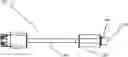
FIG. 1 shows a top view of an exemplary embodiment of the inventions.
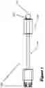
FIG. 2 shows a side view of an exemplary embodiment of the inventions.
FIG. 3 shows a perspective view of an exemplary embodiment of the inventions.
FIG. 4 shows a cut-out view of an embodiment of the inventions having a single tension spring in the compressed position.
FIG. 5 shows a cut-out view of an embodiment of the inventions having a single tension spring in the extended position.
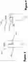
FIG. 6 shows a cut-out view of an embodiment of the inventions having double tension springs in the compressed position.
FIG. 7 shows a cut-out view of an embodiment of the inventions having a single tension spring in the extended position.
FIG. 8 shows a cut-out view of an embodiment of the inventions having a manual slider in the retracted position.
FIG. 9 shows a cut-out view of an embodiment of the inventions having a manual slider in the extended position.
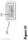
FIG. 10 shows a plan view of the top of an embodiment of the invention, in which a protective collar is seen surrounding a connector.
DETAILED DESCRIPTION OF THE PREFERRED EMBODIMENTS
Set forth below is a description of what are currently believed to be the preferred embodiments or best representative examples of the inventions disclosed and claimed herein. Present and future representations or modifications to the embodiments and preferred embodiments are also contemplated. It should be understood that the inventions are not limited in its application to the details of construction and the arrangement of components set forth in the following description or illustrated in the drawings. The invention is capable of other embodiments and of being practiced or carried out in various ways. The following discussion is presented to enable a person of ordinary skill in the art to make and use embodiments of the invention.
It is known that cables of the prior art are disadvantageous because their connector is exposed, and thus prone to breaking off. FIG. 1 shows an exemplary cable 100 embodying aspects of the present inventions. The embodiment shown includes a connector 110 mounted to plastic 120 which is in turn connected to a cable 130. FIG. 2 show an embodiment of the invention, from a side view. FIG. 3 shows an embodiment of the invention, from a perspective view. As seen in FIGS. 4 and 5, embodiments of the inventions may include a protective collar 140 which encases connector 110, and thus protects connector 110 from breaking off. In particular, FIG. 5 shows an embodiment of the inventions, with the protective collar 140 engaged and encompassing connector 110. In FIG. 4, the protective collar 140 is retracted. The protective collar 140 may be slidable between an extended position, in which the connector 110 is encased by the protective collar 140, and a retracted position, in which the connector 110 is exposed. FIG. 10 shows the relationship between protective collar 140 and connector 110, from a plan view. It can be seen that protective collar 140 is larger than connector 110, thus allowing it to surround and encage connector 110.
As explained further herein, in some embodiments, the protective collar 140 may be biased towards its extended position. Thus, in such embodiments, the connector 110 is protected by default, unless a user retracts protective collar 140. Because connector 110 is, by default, encases by protective collar 140, it is less likely to break, and thus less likely to require replacement. In the embodiments of FIGS. 4 and 5, for example, protective collar 140 is biased towards its extended position (of FIG. 5) by a single spring 150 which is positioned below the protective collar or sleeve 140. To use cable 100, a user may force protective collar 140 against the bias of spring 150 to its retracted position.
An additional embodiment is shown in FIGS. 6 and 7. Specifically, FIG. 6 shows an embodiment of the inventions in which two springs 160 and 170. Similar to the above described embodiments, spring 160 and 170 may be tension springs for biasing protective collar 140 into an extended position (FIG. 7) in which connector 110 is encased and protected.
Further yet, FIGS. 8 and 9 show additional embodiments in which a protective collar 140 is manually slidable between a retracted position and an extended position. In such embodiments, a manual track 180 may be provided to creating friction between the protective collar and the plastic 120. In some examples, the manual track 180 may be on the plastic 120 and engage a corresponding tab or track on protective collar 140. This results in friction for holding protective collar 140 into the position in which it is slid by a user. In other words, a user may manually slide protective collar 140 between an extended position and a retracted position, and protective collar 140 may remain in such position because it is held there by friction from track 180.
A user of the invention may use cable 100 (and specifically, its connector 110) to connect to a device, for example for charging a battery or for transferring data between two devices. The sleeve, i.e. protective collar 140, will be compressed when the user pushes the connector 110 into the device. The sleeve is wider than the charging opening of the device, such as a phone. While sliding the connector 110 into the phone; the protective sleeve 140 will be compressed. When the user disconnects the connector 110 from the device, the spring will retract the protective sleeve out. Connector 110 can then be inserted into a devices charging port or data transfer port, such a USB port, USB-C port, Apple's lightning port, and the like.
Protective collar 140 may be made of aluminum, plastic, plastic blends, or any other material capable of protecting connector 110. Single spring 150 or double spring 160 and 170 bias the protective collar 140 into the extended position. The springs may be tension or compression springs, or any other spring known in the art. The springs may be comprised of galvanized iron or stainless steel. Connector 110 conducts electricity from cable 100 to a device being charged. When connector 110 is connected to a device, the protective collar 140 is retracted and springs 150, 160, 170 are compressed, thus revealing connector 110. When a user disconnects the electronic device, springs 150, 160, 170 bias the protective collar 140 back to its extended position, thus protecting connector 110 from breaking or becoming otherwise damaged.
Claims
What is claimed is:1. A cable for charging electronic devices, comprising:
a cable in electronic communication with a connector;
a slidable protective sleeve attached to the cable, wherein the protective sleeve has a retracted position and an extended position, and wherein the protective sleeve encompasses the connector in the extended position; and
a first and second spring for biasing the protective sleeve to an extended position.
2. The cable of claim 1, wherein the protective sleeve is aluminum.
3. The cable of claim 1, wherein the protective sleeve is plastic.
4. The cable of claim 1, wherein the first and second springs are compression springs.
5. A cable for charging electronic devices, comprising:
a cable in electronic communication with a connector for interfacing with a mobile device;
a slidable protective sleeve attached to the cable, wherein the protective sleeve has a retracted position and an extended position, wherein the protective sleeve encompasses the connector in the extended position, and wherein the connector is exposed when the protective sleeve is in its retracted position; and
a single spring, affixed to protective sleeve's bottom, for biasing the protective sleeve to an extended position.
6. A cable for charging electronic devices, comprising:
a cable in electronic communication with a connector;
a slidable protective sleeve affixed to the cable and slidable between a retracted position and an extended position; wherein the protective sleeve is manually slidable to protect the connector.
7. The cable of claim 6, wherein the protective sleeve is aluminum.
8. The cable of claim 6, wherein the protective sleeve is plastic.
9. The cable of claim 6, wherein the first and second springs are compression springs.
Images & Drawings included:


Sources:
- United States Patent and Trademark Office - verify current appl. status at the USPTO↗
Similar patent applications:
Recent applications in this class:
- » 20250210921 2025-06-26
Multifunctional Accessory Storage Structure for Power Converter - » 20250192485 2025-06-12
Power source converter having data telescoping line - » 20250007222 2025-01-02
Power Outlet Device with Retractable Charging Cord - » 20240421544 2024-12-19
Extendable and Retractable Wall Outlet - » 20240405488 2024-12-05
ROTATABLE CABLE COLLECTION SOCKET COMPONENT - » 20240243531 2024-07-18
RETRACTABLE CABLE BOX AND ELECTRONIC DEVICE SUITABLE FOR STORING LONGER DATA CABLE - » 20240128694 2024-04-18
REEL BASED OUTLET RELOCATION/EXTENSION SYSTEM - » 20240097384 2024-03-21
CONDUCTOR ASSEMBLY FOR A POWER DISTRIBUTION SYSTEM - » 20230291154 2023-09-14
UNIVERSAL POWER CORD HANDLING DEVICE - » 20230268698 2023-08-24
Rotatable docking station with cable hold and release mechanism