Molded resin product
US20200316902A1
2020-10-08
16/831,897
2020-03-27
✅ Patent granted
US 11,273,619 B2
2022-03-15
-
-
Jeffrey A Vonch
Amin, Turocy & Watson, LLP
2040-09-05
Abstract:
A molded resin product includes a design layer including a decorative layer having a first color, a shielding layer having a second color different from the first color, and a resin base layer. A cover layer formed of a polymer film is disposed close to one end of the design layer. Part of the decorative layer exposed from the shielding layer serves as an exposed region. The exposed region and part of the shielding layer constitute a pattern portion presenting a predetermined figure or character when viewed in plan through the cover layer. The rest of the shielding layer constitutes a base portion. The layer thickness of the base portion is set smaller than the layer thickness of the pattern portion in a region thereof where the shielding layer is formed.
Inventors:
- Seonghun Lee 17 🇯🇵 Wako-shi, Japan
- Ryo Gohara 1 🇯🇵 Wako-shi, Japan
- YoungJin Hyun 2 🇸🇬 Boon Keng Road, Singapore
- Takezo Takahata 2 🇸🇬 Boon Keng Road, Singapore
- Hiroki Imai 1 🇯🇵 Tokyo, Japan
- Tomoomi Kiyomiya 5 🇯🇵 Tokyo, Japan
- Seonghun Lee 15 🇯🇵 Wako, Japan
- Ryo Gohara 1 🇯🇵 Wako, Japan
Assignee:
- CONTINENTAL AUTOMOTIVE GMBH 2,462 🇩🇪 Hannover, Germany
- HONDA MOTOR CO., LTD. 20,747 🇯🇵 Tokyo, Japan
- SUNARROW LTD 14 🇯🇵 Tokyo, Japan
Applicant:
Interested in similar patents?
Get notified when new applications in this technology area are published.
Classification:
B32B3/06 » CPC further
Layered products comprising a layer with external or internal discontinuities or unevennesses, or a layer of non-planar form ; Layered products having particular features of form characterised by features of form at particular places, e.g. in edge regions for securing layers together; for attaching the product to another member, e.g. to a support, or to another product, e.g. groove/tongue, interlocking
B32B3/18 » CPC further
Layered products comprising a layer with external or internal discontinuities or unevennesses, or a layer of non-planar form ; Layered products having particular features of form characterised by a discontinuous layer, i.e. formed of separate pieces of material characterised by an internal layer formed of separate pieces of material which are juxtaposed side-by-side
B32B2451/00 » CPC further
Decorative or ornamental articles
B32B3/30 » CPC main
Layered products comprising a layer with external or internal discontinuities or unevennesses, or a layer of non-planar form ; Layered products having particular features of form characterised by a particular shape of the outline of the cross-section of a continuous layer; characterised by a layer with cavities or internal voids ; characterised by an apertured layer characterised by a layer formed with recesses or projections, e.g. hollows, grooves, protuberances, ribs
B29C65/50 » CPC further
Joining of preformed parts ; Apparatus therefor using adhesives, i.e. using supplementary joining material; solvent bonding using adhesive tape, e.g. thermoplastic tape; using threads or the like
B32B3/263 » CPC main
Layered products comprising a layer with external or internal discontinuities or unevennesses, or a layer of non-planar form ; Layered products having particular features of form characterised by a particular shape of the outline of the cross-section of a continuous layer; characterised by a layer with cavities or internal voids ; characterised by an apertured layer characterised by a layer having non-uniform thickness
B32B3/02 » CPC further
Layered products comprising a layer with external or internal discontinuities or unevennesses, or a layer of non-planar form ; Layered products having particular features of form characterised by features of form at particular places, e.g. in edge regions
B29C65/78 IPC
Joining of preformed parts ; Apparatus therefor Means for handling the parts to be joined, e.g. for making containers or hollow articles, e.g. means for handling sheets, plates, web-like materials, tubular articles, hollow articles or elements to be joined therewith; Means for discharging the joined articles from the joining apparatus
B32B7/04 » CPC further
Layered products characterised by the relation between layers; Layered products characterised by the relative orientation of features between layers, or by the relative values of a measurable parameter between layers, i.e. products comprising layers having different physical, chemical or physicochemical properties; Layered products characterised by the interconnection of layers Interconnection of layers
E05B19/24 » CPC further
Keys; Accessories therefor Key distinguishing marks
B32B7/12 » CPC further
Layered products characterised by the relation between layers; Layered products characterised by the relative orientation of features between layers, or by the relative values of a measurable parameter between layers, i.e. products comprising layers having different physical, chemical or physicochemical properties; Layered products characterised by the interconnection of layers; Interconnection of layers using interposed adhesives or interposed materials with bonding properties
B32B3/266 » CPC further
Layered products comprising a layer with external or internal discontinuities or unevennesses, or a layer of non-planar form ; Layered products having particular features of form characterised by a particular shape of the outline of the cross-section of a continuous layer; characterised by a layer with cavities or internal voids ; characterised by an apertured layer characterised by an apertured layer, the apertures going through the whole thickness of the layer, e.g. expanded metal, perforated layer, slit layer regular cells
B32B27/08 » CPC further
Layered products comprising synthetic resin as the main or only constituent of a layer, next to another layer of a of synthetic resin
B32B7/023 » CPC further
Layered products characterised by the relation between layers; Layered products characterised by the relative orientation of features between layers, or by the relative values of a measurable parameter between layers, i.e. products comprising layers having different physical, chemical or physicochemical properties; Layered products characterised by the interconnection of layers; Physical, chemical or physicochemical properties Optical properties
B29C65/7805 » CPC further
Joining of preformed parts ; Apparatus therefor; Means for handling the parts to be joined, e.g. for making containers or hollow articles, e.g. means for handling sheets, plates, web-like materials, tubular articles, hollow articles or elements to be joined therewith; Means for discharging the joined articles from the joining apparatus; Positioning the parts to be joined, e.g. aligning, indexing or centring the parts to be joined comprising positioning features
G07C9/00944 » CPC further
Individual registration on entry or exit; Electronically operated locks; Circuits therefor; Nonmechanical keys therefor, e.g. passive or active electrical keys or other data carriers without mechanical keys Details of construction or manufacture
B32B27/30 IPC
Layered products comprising synthetic resin comprising vinyl (co)polymers; comprising acrylic (co)polymers
B32B15/082 » CPC further
Layered products comprising a layer of metal comprising metal as the main or only constituent of a layer, next to another layer of a of synthetic resin comprising vinyl resins; comprising acrylic resins
B32B27/304 » CPC further
Layered products comprising synthetic resin comprising vinyl (co)polymers; comprising acrylic (co)polymers comprising vinyl halide (co)polymers, e.g. PVC, PVDC, PVF, PVDF
B32B2250/04 » CPC further
Layers arrangement 4 layers
B32B27/40 » CPC further
Layered products comprising synthetic resin comprising polyurethanes
B32B27/36 » CPC further
Layered products comprising synthetic resin comprising polyesters
Y10T428/24182 » CPC further
Stock material or miscellaneous articles; Structurally defined web or sheet [e.g., overall dimension, etc.] including sheet or component perpendicular to plane of web or sheet Inward from edge of web or sheet
B32B15/08 » CPC further
Layered products comprising a layer of metal comprising metal as the main or only constituent of a layer, next to another layer of a of synthetic resin
B29C65/5064 » CPC further
Joining of preformed parts ; Apparatus therefor using adhesives, i.e. using supplementary joining material; solvent bonding using adhesive tape, e.g. thermoplastic tape; using threads or the like of particular form, e.g. being C-shaped, T-shaped
B29C65/7814 » CPC further
Joining of preformed parts ; Apparatus therefor; Means for handling the parts to be joined, e.g. for making containers or hollow articles, e.g. means for handling sheets, plates, web-like materials, tubular articles, hollow articles or elements to be joined therewith; Means for discharging the joined articles from the joining apparatus; Positioning the parts to be joined, e.g. aligning, indexing or centring the parts to be joined comprising positioning features in the form of inter-cooperating positioning features , e.g. tenons and mortises
B32B15/095 » CPC further
Layered products comprising a layer of metal comprising metal as the main or only constituent of a layer, next to another layer of a of synthetic resin comprising polyurethanes
E05B19/26 » CPC further
Keys; Accessories therefor Use of special materials for keys
B32B7/14 » CPC further
Layered products characterised by the relation between layers; Layered products characterised by the relative orientation of features between layers, or by the relative values of a measurable parameter between layers, i.e. products comprising layers having different physical, chemical or physicochemical properties; Layered products characterised by the interconnection of layers; Interconnection of layers using interposed adhesives or interposed materials with bonding properties applied in spaced arrangements, e.g. in stripes
B32B2250/03 » CPC further
Layers arrangement 3 layers
B32B2250/05 » CPC further
Layers arrangement 5 or more layers
B32B2255/205 » CPC further
Coating on the layer surface; Inorganic coating Metallic coating
B32B2255/26 » CPC further
Coating on the layer surface Polymeric coating
B32B2255/28 » CPC further
Coating on the layer surface Multiple coating on one surface
B32B2307/20 » CPC further
Properties of the layers or laminate having particular electrical or magnetic properties, e.g. piezoelectric
B32B2307/402 » CPC further
Properties of the layers or laminate having particular optical properties Coloured
B32B2307/4023 » CPC further
Properties of the layers or laminate having particular optical properties; Coloured on the layer surface, e.g. ink
B32B2307/41 » CPC further
Properties of the layers or laminate having particular optical properties Opaque
B32B2307/412 » CPC further
Properties of the layers or laminate having particular optical properties Transparent
B32B2307/536 » CPC further
Properties of the layers or laminate having particular mechanical properties Hardness
B32B2307/546 » CPC further
Properties of the layers or laminate having particular mechanical properties Flexural strength; Flexion stiffness
B32B2307/75 » CPC further
Properties of the layers or laminate; Other properties Printability
G07C9/00 IPC
Individual registration on entry or exit
Y10T428/24298 » CPC further
Stock material or miscellaneous articles; Structurally defined web or sheet [e.g., overall dimension, etc.] including aperture Noncircular aperture [e.g., slit, diamond, rectangular, etc.]
Y10T428/24322 » CPC further
Stock material or miscellaneous articles; Structurally defined web or sheet [e.g., overall dimension, etc.] including aperture Composite web or sheet
B32B7/022 » CPC further
Layered products characterised by the relation between layers; Layered products characterised by the relative orientation of features between layers, or by the relative values of a measurable parameter between layers, i.e. products comprising layers having different physical, chemical or physicochemical properties; Layered products characterised by the interconnection of layers; Physical, chemical or physicochemical properties Mechanical properties
Y10T428/24331 » CPC further
Stock material or miscellaneous articles; Structurally defined web or sheet [e.g., overall dimension, etc.] including aperture; Composite web or sheet including nonapertured component
Y10T428/24488 » CPC further
Stock material or miscellaneous articles; Structurally defined web or sheet [e.g., overall dimension, etc.] including variation in thickness Differential nonuniformity at margin
Y10T428/24521 » CPC further
Stock material or miscellaneous articles; Structurally defined web or sheet [e.g., overall dimension, etc.] including variation in thickness with component conforming to contour of nonplanar surface
Y10T428/24777 » CPC further
Stock material or miscellaneous articles; Structurally defined web or sheet [e.g., overall dimension, etc.] Edge feature
Y10T428/24851 » CPC further
Stock material or miscellaneous articles; Structurally defined web or sheet [e.g., overall dimension, etc.]; Discontinuous or differential coating, impregnation or bond [e.g., artwork, printing, retouched photograph, etc.] Intermediate layer is discontinuous or differential
Y10T428/24868 » CPC further
Stock material or miscellaneous articles; Structurally defined web or sheet [e.g., overall dimension, etc.]; Discontinuous or differential coating, impregnation or bond [e.g., artwork, printing, retouched photograph, etc.]; Intermediate layer is discontinuous or differential Translucent outer layer
Y10T428/28 » CPC further
Stock material or miscellaneous articles Web or sheet containing structurally defined element or component and having an adhesive outermost layer
B32B3/26 IPC
Layered products comprising a layer with external or internal discontinuities or unevennesses, or a layer of non-planar form ; Layered products having particular features of form characterised by a particular shape of the outline of the cross-section of a continuous layer; characterised by a layer with cavities or internal voids ; characterised by an apertured layer
B32B7/05 » CPC further
Layered products characterised by the relation between layers; Layered products characterised by the relative orientation of features between layers, or by the relative values of a measurable parameter between layers, i.e. products comprising layers having different physical, chemical or physicochemical properties; Layered products characterised by the interconnection of layers; Interconnection of layers the layers not being connected over the whole surface, e.g. discontinuous connection or patterned connection
B32B2250/44 » CPC further
Layers arrangement Number of layers variable across the laminate
Y10T428/24008 » CPC further
Stock material or miscellaneous articles; Structurally defined web or sheet [e.g., overall dimension, etc.] including fastener for attaching to external surface
B32B3/28 » CPC further
Layered products comprising a layer with external or internal discontinuities or unevennesses, or a layer of non-planar form ; Layered products having particular features of form characterised by a particular shape of the outline of the cross-section of a continuous layer; characterised by a layer with cavities or internal voids ; characterised by an apertured layer characterised by a layer comprising a deformed thin sheet, i.e. the layer having its entire thickness deformed out of the plane , e.g. corrugated, crumpled
B32B7/02 » CPC further
Layered products characterised by the relation between layers; Layered products characterised by the relative orientation of features between layers, or by the relative values of a measurable parameter between layers, i.e. products comprising layers having different physical, chemical or physicochemical properties; Layered products characterised by the interconnection of layers Physical, chemical or physicochemical properties
B32B27/06 » CPC further
Layered products comprising synthetic resin as the main or only constituent of a layer, next to another layer of a
B32B2307/50 » CPC further
Properties of the layers or laminate having particular mechanical properties
Y10T428/24339 » CPC further
Stock material or miscellaneous articles; Structurally defined web or sheet [e.g., overall dimension, etc.] including aperture; Composite web or sheet including nonapertured component Keyed
Y10T428/24545 » CPC further
Stock material or miscellaneous articles; Structurally defined web or sheet [e.g., overall dimension, etc.] including variation in thickness with component conforming to contour of nonplanar surface Containing metal or metal compound
Y10T428/24612 » CPC further
Stock material or miscellaneous articles; Structurally defined web or sheet [e.g., overall dimension, etc.] including variation in thickness Composite web or sheet
Y10T428/24628 » CPC further
Stock material or miscellaneous articles; Structurally defined web or sheet [e.g., overall dimension, etc.] Nonplanar uniform thickness material
Y10T428/24736 » CPC further
Stock material or miscellaneous articles; Structurally defined web or sheet [e.g., overall dimension, etc.]; Nonplanar uniform thickness material Ornamental design or indicia
Description
CROSS-REFERENCE TO RELATED APPLICATION
This application is based upon and claims the benefit of priority from Japanese Patent Application No. 2019-066181 filed on Mar. 29, 2019, the contents of which are incorporated herein by reference.
BACKGROUND OF THE INVENTION
Field of the Invention
The present invention relates to molded resin products having visible patterns such as figures and characters formed inside.
Description of the Related Art
A molded resin product provided with a design layer and a cover layer disposed on one end surface of the design layer to protect the design layer (see Japanese Laid-Open Patent Publication No. 2013-166248) has been widely used as a component constituting, for example, the so-called smart key. A decorative pattern including figures and characters is formed inside the design layer and is visible to a user through the cover layer. In this manner, the decorative pattern is an essential element of appearance visible to the user.
In a case where the molded resin product includes an object to be joined to the design layer, a joint body such as a joint tape is attached to another end surface of the design layer. As described in Japanese Laid-Open Patent Publication No. 2005-113085, the object is joined to the design layer via the joint body.
SUMMARY OF THE INVENTION
It is assumed that the design layer may be joined to an object of which joint surface is curved. In this case, the design layer is required to be flexible enough to curve along the curved surface. Moreover, since the smart key is carried by the user, the molded resin product is required to be as light as possible.
A principal object of the present invention is to provide a molded resin product demonstrating sufficient flexibility.
Another object of the present invention is to provide a lightweight molded resin product.
According to an embodiment of the present invention, a molded resin product comprises:
a cover layer formed of a polymer film; and
a design layer disposed close to one end surface of the cover layer and visible through the cover layer,
wherein the design layer includes:
a decorative layer having a first color;
a shielding layer having a second color different from the first color and configured to cover a shielded region, which is part of the decorative layer, when viewed in plan through the cover layer; and
a resin base layer disposed adjacent to the cover layer and configured to cover the shielding layer and an exposed region of the decorative layer exposed from the shielding layer,
wherein the exposed region and part of the shielding layer constitute a pattern portion presenting a predetermined figure or character when viewed in plan through the cover layer and the resin base layer,
wherein rest of the shielding layer except for the part of the shielding layer constitutes a plain base portion when viewed in plan through the cover layer and the resin base layer, and
wherein a layer thickness of the base portion is set smaller than a layer thickness of the pattern portion in a region thereof where the shielding layer is formed.
According to the present invention, the layer thickness of the base portion is set smaller than the layer thickness of the pattern portion. Thus, the base portion, and by extension the design layer, can demonstrate sufficient flexibility. Consequently, in a case where the molded resin product includes an object to which the design layer is joined, the design layer can be easily joined to the object even when the joint surface of the object is curved. This results in the molded resin product with an excellent appearance.
Moreover, the weight of the molded resin product can be reduced since the layer thickness is small. Thus, in a case where the molded resin product constitutes portable equipment such as a smart key, the portable equipment becomes light and thus easy for the user to carry.
The above and other objects, features, and advantages of the present invention will become more apparent from the following description when taken in conjunction with the accompanying drawings in which a preferred embodiment of the present invention is shown by way of illustrative example.
BRIEF DESCRIPTION OF THE DRAWINGS
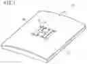
FIG. 1 is an overall schematic perspective view of a molded resin product according to an embodiment of the present invention;
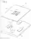
FIG. 2 is an exploded perspective view of the molded resin product in FIG. 1;
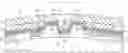
FIG. 3 is a cross-sectional view of the molded resin product in FIG. 1 taken along the direction of lamination (thickness direction); and
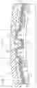
FIG. 4 is a schematic cross-sectional view of a principal part illustrating a state where a laminate constituting the molded resin product in FIG. 1 is curved to be joined to an object.
DESCRIPTION OF THE PREFERRED EMBODIMENT
A preferred embodiment of a molded resin product according to the present invention will be described in detail below with reference to the accompanying drawings.
FIGS. 1 to 3 are respectively an overall schematic perspective view, an exploded perspective view, and a cross-sectional view in the direction of lamination (thickness direction) of a molded resin product 10 according to this embodiment. The molded resin product 10 includes an object 12 and a laminate 14 joined to the object 12.
In the upper surface 18 of the object 12, end portions in the width direction are gently curved to expand from edge portions toward the middle in the width direction. In other words, the object 12 is slightly rounded.
In this case, the object 12 is a casing accommodating electronic components such as a circuit board (not illustrated) inside. As illustrated in FIGS. 2 and 3, a plurality of (five in FIG. 2) hollow protrusions 16 protrude from the flat upper surface 18 to prevent interference with the electronic components accommodated inside the object 12. Consequently, the flat upper surface 18 of the object 12 serves as a depression hollowed relative to the hollow protrusions 16.
The laminate 14 is joined to the object 12 via a joint tape 20 illustrated in FIG. 3. In addition, guide tapes 22 are disposed between the object 12 and the laminate 14. The joint tape 20 and the guide tapes 22 will be described later.
The laminate 14 includes a design layer 30 and a cover layer 32. The design layer 30 includes a base portion 34 and a pattern portion 36. In this case, the pattern portion 36 includes a decorative character “H”. The decorative character “H” is visible to a user as if to be raised from the base portion 34 in a three-dimensional manner.
As illustrated in FIG. 3, the design layer 30 includes a resin base layer 40. Hereinafter, the bottom of the resin base layer 40 in FIG. 3 is referred to as the lower end, and the top is referred to as the upper end. The lower end is provided with two elongated depressions 42a and 42b extending into the page in FIG. 3. The depressions 42a and 42b respectively correspond to two longitudinal leg portions of the decorative character “H”.
The depressions 42a and 42b are hollowed toward the upper end (toward the cover layer 32). Moreover, the depressions 42a and 42b become deeper as they become closer each other. That is, the depressions 42a and 42b are deepest at positions closest to each other and shallowest at positions farthest from each other. The depth of a depression (not illustrated) constituting a lateral bar portion of the decorative character “H” is substantially identical to the depth of the depressions 42a and 42b at the deepest parts.
A metal layer 44 (decorative layer) constituting the pattern portion 36 is disposed below the overall lower end surface of the resin base layer 40 including the depressions 42a and 42b. The metal layer 44 is covered with a print layer 46 serving as a shielding layer except for exposed regions 44a. When the user views the molded resin product 10 or the laminate 14 from above the cover layer 32, the exposed regions 44a are visible to the user. Adding a shine to the metal layer 44 further improves the design quality. The exposed regions 44a form an “H” shape as a whole and are visually identified as the decorative character “H” by the user.
Regions of the metal layer 44 except for the exposed regions 44a are shielded regions 44b covered (shielded) with the print layer 46. In other words, the print layer 46 is interposed between the resin base layer 40 and the metal layer 44 in the shielded regions 44b. As a result, the shielded regions 44b are hidden behind the print layer 46 and are invisible to the user using the molded resin product 10.
The print layer 46 has a different color from that of the metal layer 44. The print layer 46 is preferably black since the color increases the contrast between the print layer 46 and the shiny metal layer 44 and thus improves the appearance of the exposed regions 44a, in other words, the decorative character “H”.
Materials suitable for the metal layer 44 include indium, tin, and alloys of these. In a case where the molded resin product 10 is used as a smart key, the smart key can communicate with a vehicle body without being interfered since radio waves can pass through those metals. On the other hand, materials suitable for the print layer 46 include urethane resin and vinyl chloride resin.
In this embodiment, the resin base layer 40 is composed of an ultraviolet curable resin. Since ultraviolet curable resins are relatively soft, the laminate 14 easily curves when subjected to an external force that causes the laminate 14 to curve. In this manner, the resin base layer 40 composed of an ultraviolet curable resin provides the laminate 14 with flexibility.
The print layer 46 is more flexible than the resin base layer 40. That is, the print layer 46 has a higher percentage of elongation than the resin base layer 40 and a lower Shore D hardness than the resin base layer 40. As a result, the print layer 46 and the metal layer 44 easily bend (curve) along the resin base layer 40. Thus, separation of the print layer 46 and the metal layer 44 from the resin base layer 40 caused by the differences in flexibility is prevented.
The percentage of elongation is measured in compliance with the so-called Method B specified in JIS K 7161 (based on the ASTM D 638). The percentages of elongation of the resin base layer 40 and the print layer 46 are, for example, about 1-100% and 1-200%, respectively. Moreover, the Shore D hardnesses of the resin base layer 40 and the print layer 46 are, for example, about 60°-90° and 70°-90°, respectively.
The upper end of the resin base layer 40 adjacent to the middle in the width direction is defined as a flat portion. The cover layer 32 is disposed on the upper surface of the resin base layer 40. The cover layer 32 is formed of a polymer film. Suitable examples of polymers include polyethylene terephthalate (PET).
The resin base layer 40 and the cover layer 32 are thin and transparent enough to pass light. For this reason, when the user views (looks down at) the molded resin product 10 in plan view from outside the cover layer 32, the exposed regions 44a of the metal layer 44, that is, the decorative character “H”, is easily visible.
A holding layer 48 is disposed on the lower surface of the metal layer 44 to prevent the print layer 46 and the metal layer 44 from falling off the resin base layer 40. The holding layer 48 is composed of, for example, urethane resin, vinyl chloride resin, or the like, and has a shape along the metal layer 44.
The pattern portion 36 is a part inside a virtual area A1 (see FIGS. 1 and 2) enclosing the outermost edge portions of the decorative character “H”. Thus, the pattern portion 36 includes the exposed regions 44a visually identified as the decorative character “H”, the shielded regions 44b inside the virtual area A1, the print layer 46 covering the shielded regions 44b inside the virtual area A1, and the resin base layer 40 and the holding layer 48 inside the virtual area A1. In contrast, the base portion 34 is a part outside the virtual area A1. That is, the base portion 34 includes the shielded region 44b outside the virtual area A1, the print layer 46 covering the shielded region 44b outside the virtual area A1, and the resin base layer 40 and the holding layer 48 outside the virtual area A1.
As can be seen from FIG. 3, the thickness T1 of the resin base layer 40 in the base portion 34 (outside the virtual area A1) is set smaller than the thickness T2 of the resin base layer 40 in a region thereof where the print layer 46 is formed in the pattern portion 36 (inside the virtual area A1). As a result, the layer thickness in the base portion 34 is smaller than the layer thickness in the pattern portion 36 in the region thereof where the print layer 46 exists. Note that the layer thickness in the pattern portion 36 at the depressions 42a and 42b, which is the sum total of the thicknesses of the holding layer 48, the metal layer 44 (the exposed regions 44a), and the resin base layer 40, is smaller than the two layer thicknesses described above.
Moreover, the joint tape 20 (joint body) for joining the laminate 14 to the object 12 and the guide tapes 22 (guide body) brought into contact with the hollow protrusions 16 during joining are attached to the base portion 34. The joint tape 20 is a double-sided tape, and the guide tapes 22 are single-sided tapes. Moreover, the joint tape 20 is thicker than the guide tapes 22.
The joint tape 20 is disposed at a position corresponding to the flat upper surface 18 of the object 12. On the other hand, the guide tapes 22 are disposed at positions corresponding to the hollow protrusions 16. Consequently, the joint tape 20 and the guide tapes 22 are separated from each other. Note that either the joint tape 20 or the guide tapes 22 are not disposed on the pattern portion 36. Moreover, the adhesive surfaces of the guide tapes 22 face the lower end surface of the laminate 14.
The molded resin product 10 according to this embodiment is basically configured as above. Next, the operational effects thereof will be described.
The laminate 14 is affixed to the object 12 (for example, casing of a smart key) via the joint tape 20. When the laminate 14 is placed on top of the object 12 before being affixed, the posture, position, and the like of the laminate 14 may be set such that the guide tapes 22 are disposed above the hollow protrusions 16 to be brought into contact with the hollow protrusions 16. This determines the positions of the laminate 14 and the object 12 relative to each other, enabling the laminate 14 to be easily affixed, in other words, joined to the object 12.
Since the guide tapes 22 are single-sided tapes, the guide tapes 22 are only brought into contact with the hollow protrusions 16 and are not involved in joining the design layer 30 of the laminate 14 to the object 12. In other words, only the joint tape 20, which is a double-sided tape, is involved in joining the design layer 30 (laminate 14) to the object 12. As a result, while the adhesion is still insufficient immediately after the joint tape 20 is temporarily affixed to the object 12, the position of the laminate 14 can be easily adjusted before the laminate 14 is pressed against the object 12.
In the case where the curved surfaces exist at the end portions of the object 12 in the width direction as illustrated in FIG. 4, the laminate 14 curves along the curved surfaces of the object 12. The resin base layer 40 is composed of an ultraviolet curable resin, which is relatively flexible. Moreover, in this embodiment, the thickness T1 of the resin base layer 40 in the base portion 34 (outside the virtual area A1) is smaller than the thickness T2 of the resin base layer 40 at the print layer 46 in the pattern portion 36 (inside the virtual area A1). As a result, the flexibility of the resin base layer 40 is sufficiently increased.
Moreover, the print layer 46 is flexible compared with the resin base layer 40. For this reason, the print layer 46 easily bends (curves) along the resin base layer 40. Thus, the laminate 14 can easily curves due to its excellent flexibility, and the molded resin product 10 can be easily affixed to the rounded object 12.
In addition, since the thickness T1 of the resin base layer 40 in the base portion 34 is sufficiently small, the layer thickness of the overall laminate 14 and the weight of the molded resin product 10 are reduced.
To join the laminate 14 to the object 12 via the sufficient adhesion of the joint tape 20, a worker presses the laminate 14 against the object 12 using their fingers. In a case where the joint tape 20 or the guide tapes 22 are affixed to the pattern portion 36, it is assumed that the joint tape 20 or the guide tapes 22 are squashed and spread over wider areas than the metal layer 44 or the print layer 46 when the laminate 14 is joined to the object 12. In this case, the joint tape 20 or the guide tapes 22 may be visible when viewed from the side on which the cover layer 32 lies and may ruin the appearance of the laminate 14.
However, in this embodiment, the joint tape 20 and the guide tapes 22 are not affixed to the pattern portion 36 but only to the base portion 34. This eliminates the above-described concern. That is, the excellent appearance of the laminate 14, and by extension the molded resin product 10, can be maintained.
Furthermore, the thin guide tapes 22 are disposed at the positions corresponding to the hollow protrusions 16, and the thick joint tape 20 is disposed at the position corresponding to the flat upper surface 18 serving as the depression relative to the hollow protrusions 16. Thus, even when the laminate 14 including the design layer 30 and the cover layer 32, which are both thin, is joined to the object 12, protrusions or a depression corresponding to the hollow protrusions 16 or the upper surface 18 is prevented from being formed in the design layer 30 and the cover layer 32. That is, the cover layer 32 becomes substantially flat although the joint surface of the object 12 is uneven.
In addition, the laminate 14 is less depressed when the worker presses the laminate 14. For the above-described reasons, the appearance of the pattern portion 36, in particular, the decorative character “H” is improved.
Yet moreover, the joint tape 20 and the guide tapes 22 are separated from each other (see FIG. 3, in particular). As a result, flow paths 60 are formed between the joint tape 20 and the guide tapes 22. When the laminate 14 is joined to the object 12, in other words, when the laminate 14 and the object 12 are brought into firm contact with each other, the air lying between the laminate 14 and the object 12 is discharged to the outside through the flow paths 60. This prevents the air from remaining between the laminate 14 and the object 12 and thereby prevents air bubbles from being produced.
The molded resin product 10 is obtained by joining the laminate 14 to the object 12. When the user visually checks the molded resin product 10 from the side on which the cover layer 32 lies, only the regions of the metal layer 44 not shielded with the print layer 46, that is, the exposed regions 44a in the depressions 42a and 42b, are visible. Since the depressions 42a and 42b have three-dimensional shapes hollowed toward the cover layer 32, the user identifies the decorative character “H” in the pattern portion 36 as a three-dimensional decoration. In this manner, according to this embodiment, the pattern portion 36 including the decorative character “H” with an excellent three-dimensional appearance can be easily provided.
The present invention is not limited in particular to the embodiment described above, and various modifications can be made thereto without departing from the scope of the present invention.
For example, the holding layer 48 may be formed as required, that is, may be omitted depending on the joint strength between the metal layer 44 and the resin base layer 40.
Moreover, although the laminate 14 is affixed to the curved surface of the object 12 in this embodiment, the laminate 14 may be affixed to a flat, uncurved surface as a matter of course.
Claims
What is claimed is:1. A molded resin product comprising:
a cover layer formed of a polymer film; and
a design layer disposed close to one end surface of the cover layer and visible through the cover layer;
wherein the design layer includes:
a decorative layer having a first color;
a shielding layer having a second color different from the first color and configured to cover a shielded region, which is part of the decorative layer, when viewed in plan through the cover layer; and
a resin base layer disposed adjacent to the cover layer and configured to cover the shielding layer and an exposed region of the decorative layer exposed from the shielding layer,
wherein the exposed region and part of the shielding layer constitute a pattern portion presenting a predetermined figure or character when viewed in plan through the cover layer and the resin base layer,
wherein rest of the shielding layer except for the part of the shielding layer constitutes a plain base portion when viewed in plan through the cover layer and the resin base layer, and
wherein a layer thickness of the base portion is set smaller than a layer thickness of the pattern portion in a region thereof where the shielding layer is formed.
2. The molded resin product according to claim 1, wherein a layer thickness of the resin base layer in a region thereof where the base portion is formed is set smaller than a layer thickness of the resin base layer in a region thereof where the pattern portion is formed.
3. The molded resin product according to claim 1, further comprising:
an object joined to the base portion via a joint body.
4. The molded resin product according to claim 3, wherein:
the object includes a protrusion protruding toward the design layer, and a depression hollowed relative to the protrusion; and
the depression is joined to the base portion via the joint body, and a guide body brought into contact with the protrusion is provided in the base portion.
5. The molded resin product according to claim 4, wherein a thickness of the joint body is larger than a thickness of the guide body.
6. The molded resin product according to claim 4, wherein the joint body and the guide body are separated from each other.
7. The molded resin product according to claim 4, wherein the joint body is a double-sided tape, and the guide body is a single-sided tape.
Images & Drawings included:

Sources:
- United States Patent and Trademark Office - verify current appl. status at the USPTO↗
Similar patent applications:
- » 20240075665
MOLDED RESIN PRODUCT, METHOD FOR MANUFACTURING MOLDED RESIN PRODUCT, MOLD, AND APPARATUS FOR MANUFACTURING MOLDED RESIN PRODUCT - » 20210308917
Molded resin product, method for manufacturing molded resin product, mold, and apparatus for manufacturing molded resin product - » 20080051507
Resin composition, resin molding product, production method of resin molding product and recycling method of resin molding product - » 20200012211
Resin molded product, resin laminate, cartridge, image-forming apparatus, method for manufacturing resin molded product, method for manufacturing resin laminate, and method for manufacturing cartridge - » 20160332343
Molding method of resin molded product and resin molded product - » 20150174799
MOLDING METHOD OF RESIN MOLDED PRODUCT AND RESIN MOLDED PRODUCT - » 20110281048
RESIN COMPOSITION FOR DISPOSAL RESIN MOLDED PRODUCT, AND DISPOSAL RESIN MOLDED PRODUCT - » 20090051075
Methods of forming imprint on resin-molded product, and resin-molded product - » 20110143128
Decorative sheet, process for producing decorative resin molded product, and decorative resin molded product - » 20140065384
Decorative sheet, process for producing decorative resin molded product, and decorative resin molded product
Recent applications in this class:
- » 20250249654 2025-08-07
WINDOW AND ELECTRONIC DEVICE INCLUDING THE SAME - » 20250249653 2025-08-07
MULTI-LAYERED STRUCTURE AND METHOD OF MANUFACTURING THE SAME - » 20250242563 2025-07-31
DECORATIVE SHEET - » 20250222674 2025-07-10
Decorative Substrate, Preparation Method Therefor and Application Thereof - » 20250214315 2025-07-03
VEHICLE INTERIOR MATERIAL - » 20250205991 2025-06-26
DECORATIVE SHEET AND METHOD FOR MANUFACTURING DECORATIVE SHEET - » 20250196467 2025-06-19
LAYERED ARTICLE INCLUDING SYNTHETIC POLYMER FILM HAVING ANTIMICROBIAL AND/OR ANTIVIRAL PROPERTIES, AND METHOD FOR PRODUCING THE SAME - » 20250196466 2025-06-19
BUFFER MATERIAL, EXTERIOR MATERIAL, AND ROBOT COMPONENT - » 20250144910 2025-05-08
STRAND SIDING WITH PEBBLED STUCCO TEXTURE - » 20250128495 2025-04-24
SURFACE MATERIALS AND METHOD OF MANUFACTURE
Recent applications for this Assignee:
- » 20250293548 2025-09-18
POWER TRANSMISSION DEVICE AND POWER RECEPTION DEVICE - » 20250289343 2025-09-18
INFORMATION PROCESSING SYSTEM, MOVING OBJECT DEVICE, AND POWER SUPPLY DEVICE - » 20250289329 2025-09-18
POWER RECEPTION DEVICE - » 20250289328 2025-09-18
POWER TRANSMISSION DEVICE AND POWER RECEPTION DEVICE - » 20250289327 2025-09-18
POWER TRANSMISSION DEVICE - » 20250286234 2025-09-11
BATTERY DEVICE - » 20250284006 2025-09-11
LIDARGRID A 3D OPACITY GRID FROM LIDAR FOR SCENE FORECASTING - » 20250282369 2025-09-11
VEHICLE - » 20250282349 2025-09-11
VEHICLE CONTROL DEVICE - » 20250278165 2025-09-04
Virtual tools for supported tele-operations