Door jalmb jigs
US20200325692A1
2020-10-15
16/501,422
2019-04-11
Abstract:
The current invention comprises a set of Door Jamb Jigs designed to enable the user to temporarily hold a carpenters level, a carpenters square, and a door jamb firmly within the rough opening of a framed wall so that the door jamb can be permanently nailed in place pre-squared, pre-leveled, and pre-plumb. The current invention utilizes universally designed Jigs that enable users to utilize their own conventional carpenters square and carpenters level combined with the Door Jamb Jigs to practice a new method of installing pre-hung interior doors much easer, faster and more accurately compared to the conventional practice of holding tools by hand. The current invention solves problems during the Pre-hung door jamb installation process. #1 The invention enables the user to temporarily attach both a 90 degree carpenters square and a carpenters level to the door jamb so when the door panel is reattached to the jamb the clearance between the door panel and the door jamb is equal and parallel all around. #2 By using this method of pre-squaring the head of the jamb in relation to the hinge side of the jamb, and pre-straightening the hinge side of the jamb with the carpenters level attached to the jamb pre-plumb the user can accurately determine how much shimming is required to allow for twisted framing lumber. Thus eliminating jamb torque, and bound hinges. #3 By adjusting the standoff screws the jamb be positioned flush with the finished wall.
Interested in similar patents?
Get notified when new applications in this technology area are published.
Classification:
E04F21/0015 » CPC main
Implements for finishing work on buildings for mounting doors, windows or frames; their fitting for mounting frames
E04F21/00 IPC
Implements for finishing work on buildings
Description
CROSS REFERENCE TO RELATED APPLICATIONS
N/A
BACKGROUND-PRIOR ART
The present invention relates to carpentry hand tools and more specifically to Carpenter framing squares and carpenter levels.
Problems that are solved while installing a pre-hung door. Obviously a person can't be on both sides of a door at the same time when the door is closed. So the installer must remove the door from the jamb.
Problem #1 . . . Once the door is removed the jambs are no longer straight. The invention solves this problem as the jamb is temporally affixed to a 6 foot level on the hinge side. Problem #2 When the jamb is not attached to the door, the head goes out of square in relation to the jamb legs. The invention solves this problem as the framing square and jigs are forcing the head jamb to be 90 degrees square in relation to the hinge side of the door jamb.
Problem #3 The jambs need to be installed plumb, level and square before installing shims between the jamb and the rough frame opening. To make things worse the rough framing studs are twisted so shimming is never equal on each side of the opening. Shimming is guess work, trial and error. Also the jambs need to be 1/32 proud of the finish wall on each side of the wall. The invention solves all of the above problems simultaneously as the Door Jamb Jigs are affixed to the hinge side of the door jamb and the head jamb. The framing square and carpenters level are integrated and sandwiched between the wood jamb and inward protruding jamb stops within the jig body. Once the entire assemble is screwed thru the drywall into the framing studs, the jamb can be adjusted plumb, level, square and 1/32 proud of the finish wall all before shimming. The installer can then determine exactly how much shimming is required on each side between the jamb and the rough frame opening without twisting the jamb thus, eliminating jamb torque and hinge binding.
SUMMARY
The purpose of the invention is to integrate a carpenters level and a carpenters framing square, affixing them to a door jamb temporarily during permanent installation of a pre-hung door. The utility of the embodiment enables the user to accurately shim door jambs in the proper position much faster and easier compared to other methods.
BRIEF LIST OF DRAWINGS
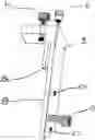
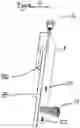
FIG. 1. Illustrates the in use perspective view.
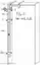
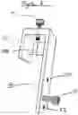
FIG. 2. Illustrates a sectional view in use.
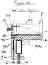
FIG. 3. Illustrates a perspective view of #1 FIG. 1 upper level squaring jig.
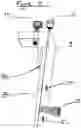
FIG. 4. Illustrates a perspective view of #3 FIG. 1 head squaring jig.
FIG. 5. Illustrates a perspective view of #5a FIG. 1 lower jig for level only.
DRAWINGS—REFERENCE NUMERALS
FIG. 1.
| 1 | upper level squaring jigs | 3 | head squaring jig |
| 5a | lower jig for level only | 7a | conventional wood door jamb |
| 18a | carpenters framing square | 20a | carpenters level |
FIG. 2.
| 1 | L-shaped jig body | 18b | framing square slot |
| 8 | inward protruding jamb | 4 | level binder |
| stop | |||
| 6 | framing sq. binder | 10 | drywall standoff adjuster |
| 26 | 2 × 4 wood jack stud | 12 | drywall |
| 14 | wood shims | 16 | wooden door jamb |
| 20a | carpenters level | ||
| 18a | carpenters framing square | 24 | jamb mounting hole & screw |
| 22 | wall mount hole & screw | ||
FIG. 3.
| 8 | inward protruding jamb stop | 18b | framing square slot |
| 1 | L-shaped jig body | ||
| 4 | level binder | 6 | square binder |
| 24 | jamb mounting hole | 10 | drywall standoff adjuster |
| 22 | wall mounting hole | ||
FIG. 4.
| 6 | square binder | 3 | slotted jig body (square only) |
| 24 | jamb mounting hole | 10 | drywall standoff adjuster |
| 22 | wall mounting hole | 8 | inward protruding jamb stop |
| 18 | framing square slot | ||
FIG. 5.
| 4 | level binder | 22 | wall mounting hole |
| 5c | J-channel jig body | 10 | drywall standoff adjuster |
| 20b | level pocket | 24 | jamb mounting hole |
| 8 | inward protruding jamb stop | ||
The present disclosure is to be considered as an exemplification of the invention, and is not intended to limit the invention to the specific embodiments illustrated by the figures below.
FIG. 1. depicts a perspective view that comprises three unique embodiments, #1 The upper level squaring jig #3 the head squaring jig and 5a the lower jig for level only.
The method of attachment described below for these jigs are similar and illustrated in FIG. 2 as follows.
FIG. 2 is a sectional view of #1 FIG. 1 level & squaring jig. This illustrates the positioning of the embodiment a method of temporarily affixing and sandwiching a carpenters level a carpenters framing square and the illustrated wood door jamb #16. A method of temporary attachment via #22 & #24 wood screws directly thru #12 wallboard into #26 wood frame and #16 wood jamb. Illustration #18a is a carpenters framing square sandwiched within #18b the framing square slot. Framing square #18a is integrated into final position by #6 framing square binder. A carpenters level illustrated by #20a is integrated between #4 level binder thus urging #20a into final position between #4 and #16 illustrated wood jamb and #8 inward protruding jamb stop.
FIG. 3 is a perspective view of #1 FIG. 1. #8 The inward projecting jamb stop is attached to or part of #1 L-shaped jig body.
#18b The framing square slot is an embodiment of the L shaped jig body. #4 Level binder and #6 framing square binder urge into final position proposed carpenters level & carpenters square between the proposed wood jamb and #8 inward protruding jamb stop. Orifice #24 is a jamb mounting hole. A mechanical means #10 described as a drywall standoff adjustment. Orifice #22 is a wall mounting hole.
DESCRIPTION OF ADDITIONAL EMBODIMENT
FIG. 4 is a perspective view illustrated as #3 FIG. 1 Head squaring Jig
| Drawing Reference Numerals |
| #18b | framing square slot | ||
| #3 | slotted jig body (square | #8 | inward protruding jamb |
| only) | stop | ||
| #22 | wall mounting hole | # 24 | jamb mounting hole |
| #10 | drywall standoff adjuster | #6 | framing square binder |
CONCLUSIONS, RAMIFICATIONS AND SCOPE
A universal accessory device designed to integrate a 90 degree carpenters framing square or similar too square combined with a carpenters level affixed to a door jamb temporarily positioned within the rough opening of a wall. The jamb can then be shimmed in place faster, easier and with greater accuracy compared to other and conventional methods. The jig body can be any flat rigid material, bent molded, extruded, 3 D printed or assembled into a similar shape to facilitate the embodiment.
The level binding and square binding parts can be metal, plastic, or any hard material, by any mechanical means to function in a similar way. The jamb stops can also be molded, bent, extruded, screwed, 3D printed or assembled in a location to function in the exact or similar way illustrated in the drawings.
Claims
I claim:1. An accessory device of mechanical means and structural slot for urging integration of a 90 degree carpenters square and a carpenters level contiguously sandwiching affixing and binding said combination of tools temporarily to a door jamb comprising an L shaped jig body with a slot to accommodate a proposed carpenters framing square and a protrusion within said jig body that can bind a door jamb between said mechanical means said jig body said level and said square simultaneously.
Images & Drawings included:
Sources:
- United States Patent and Trademark Office - verify current appl. status at the USPTO↗
Recent applications in this class:
- » 20250154778 2025-05-15
DOOR INSTALLATION APPARATUS - » 20240247502 2024-07-25
FRAME-POSITIONING DEVICE AND METHOD FOR POSITIONING A FRAME - » 20240026692 2024-01-25
DOOR FRAME SUPPORT ARRANGEMENT AND METHOD THEREFOR - » 20230287692 2023-09-14
Self-aligning jamb jack screw - » 20220372769 2022-11-24
Templating device - » 20200157823 2020-05-21
Adjustable door frame spreader tool - » 20200095782 2020-03-26
Door hanger bracket - » 20160319557 2016-11-03
Door assembly installation tool - » 20160138276 2016-05-19
JAMB INSTALLATION DEVICE AND METHOD - » 20150300031 2015-10-22
Adjustable Door Frame Spreader Tool