Cable structure
US20200328012A1
2020-10-15
16/452,676
2019-06-26
✅ Patent granted
US 10,784,022 B1
2020-09-22
-
-
Chau N Nguyen
Lin & Associates Intellectual Property, Inc.
2039-06-26
Abstract:
A cable structure includes at least one stuffing element, a first transmission module surrounding outside the at least one stuffing element, a first shielding layer surrounding outside the first transmission module, a second transmission module surrounding outside the first shielding layer, a second shielding layer surrounding outside the second transmission module, a woven layer surrounding outside the second shielding layer, an insulating skin surrounding outside the woven layer, a plurality of first core wire assemblies disposed in the first transmission module and the second transmission module, respectively, and at least one second core wire assembly disposed in the first transmission module or the second transmission module. A diameter of each first core wire assembly is different from a diameter of each second core wire assembly.
Assignee:
- Cheng Uei Precision Industry Co., LTD. 388 🇹🇼 New Taipei, Taiwan
Applicant:
Interested in similar patents?
Get notified when new applications in this technology area are published.
Classification:
H01B3/441 » CPC further
Insulators or insulating bodies characterised by the insulating materials; Selection of materials for their insulating or dielectric properties mainly consisting of organic substances plastics; resins; waxes vinyl resins; acrylic resins from alkenes
H01B11/18 IPC
Communication cables or conductors Coaxial cables; Analogous cables having more than one inner conductor within a common outer conductor
H01B3/44 IPC
Insulators or insulating bodies characterised by the insulating materials; Selection of materials for their insulating or dielectric properties mainly consisting of organic substances plastics; resins; waxes vinyl resins; acrylic resins
H01B7/02 » CPC further
Insulated conductors or cables characterised by their form Disposition of insulation
H01B11/1895 » CPC main
Communication cables or conductors; Coaxial cables; Analogous cables having more than one inner conductor within a common outer conductor Particular features or applications
H01B11/1891 » CPC further
Communication cables or conductors; Coaxial cables; Analogous cables having more than one inner conductor within a common outer conductor comprising auxiliary conductors
H01B11/04 IPC
Communication cables or conductors; Cables with twisted pairs or quads with pairs or quads mutually positioned to reduce cross-talk
Description
BACKGROUND OF THE INVENTION
1. Field of the Invention
The present invention generally relates to a cable structure, and more particularly to a cable structure for making conductive wires of the cable structure maintain stable electrical signal transmissions in designs of the conductive wires of the cable structure with different lengths.
2. The Related Art
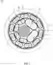
With reference to FIG. 2, a sectional view of a cable structure 100′ in prior art is shown. The cable structure 100′ includes at least one stuffing element 1′, a first transmission module 2′, a first shielding layer 3′, a second transmission module 4′, a second shielding layer 5′, a woven layer 6′ and an insulating skin 7′ arranged in sequence, and arranged from an inside of the cable structure 100′ to an outside of the cable structure 100′. The at least one stuffing element 1′ is disposed in a center of the cable structure 100′. The first transmission module 2′ surrounds outside the at least one stuffing element 1′. The first shielding layer 3′ surrounds outside the first transmission module 2′. The second transmission module 4′ surrounds outside the first shielding layer 3′. The second shielding layer 5′ surrounds outside the second transmission module 4′. The woven layer 6′ surrounds outside the second shielding layer 5′. The insulating skin 7′ surrounds outside the woven layer 6′. The cable structure 100′ further includes a plurality of core wire assemblies 8′ disposed in the first transmission module 2′ and the second transmission module 4′, respectively. Each core wire assembly 8′ has at least two conductive wires 81′ and at least one ground wire 82′. A wire diameter of each conductive wire 81′ is 30 AWG (American Wire Gauge).
However, when the cable structure 100′ in the prior art with the increase of a length of each conductive wire 81′, insertion losses of conductive wires 81′ of some of the plurality of the core wire assemblies 8′ are excessive, so that the cable structure 100′ cannot satisfy a high frequency specification, thereby affecting an electrical signal transmission of the cable structure 100′.
Therefore, it is necessary to provide an innovative cable structure, and the innovative cable structure is applied for making conductive wires of the innovative cable structure maintain stable electrical signal transmissions in designs of the conductive wires of the innovative cable structure with different lengths.
SUMMARY OF THE INVENTION
An object of the present invention is to provide a cable structure. The cable structure includes at least one stuffing element, a first transmission module surrounding outside the at least one stuffing element, a first shielding layer surrounding outside the first transmission module, a second transmission module surrounding outside the first shielding layer, a second shielding layer surrounding outside the second transmission module, a woven layer surrounding outside the second shielding layer, an insulating skin surrounding outside the woven layer, a plurality of first core wire assemblies disposed in the first transmission module and the second transmission module, respectively, and at least one second core wire assembly disposed in the first transmission module or the second transmission module. A diameter of each first core wire assembly is different from a diameter of each second core wire assembly.
As described above, because the cable structure includes the plurality of the first core wire assemblies and the at least one second core wire assembly , so the cable structure is applied for making the cable structure maintain stable electrical signal transmissions in designs of the cable structure with the different lengths.
BRIEF DESCRIPTION OF THE DRAWINGS
The present invention will be apparent to those skilled in the art by reading the following description, with reference to the attached drawings, in which:
FIG. 1 is a sectional view of a cable structure in accordance with a preferred embodiment of the present invention;
FIG. 2 is a sectional view of a cable structure in prior art.
DETAILED DESCRIPTION OF THE PREFERRED EMBODIMENT
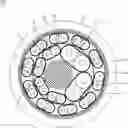
With reference to FIG. 1, a cable structure 100 in accordance with a first preferred embodiment of the present invention is shown. The cable structure 100, includes at least one stuffing element 1, a first transmission module 2, a first shielding layer 3, a second transmission module 4, a second shielding layer 5, a woven layer 6 and an insulating skin 7.
The first transmission module 2 surrounds outside the at least one stuffing element 1. The first shielding layer 3 surrounds outside the first transmission module 2. The second transmission module 4 surrounds outside the first shielding layer 3. The second shielding layer 5 surrounds outside the second transmission module 4. The woven layer 6 surrounds outside the second shielding layer 5. The insulating skin 7 surrounds outside the woven layer 6.
The cable structure 100 further includes a plurality of first core wire assemblies 8 disposed in the first transmission module 2 and the second transmission module 4, respectively. The cable structure 100 further includes at least one second core wire assembly 9 disposed in the first transmission module 2 or the second transmission module 4. A diameter of each first core wire assembly 8 is different from a diameter of each second core wire assembly 9. Specifically, a long diameter of each first core wire assembly 8 is different from a long diameter of each second core wire assembly 9. A short diameter of each first core wire assembly 8 is different from a short diameter of each second core wire assembly 9.
In this preferred embodiment, each first core wire assembly 8 includes at least one first conductive wire 81 and at least one first ground wire 82. Each second core wire assembly 9 includes at least one second conductive wire 91 and at least one second ground wire 92. A wire diameter of the at least one first conductive wire 81 of each first core wire assembly 8 is different from a wire diameter of the at least one first ground wire 82 of each first core wire assembly 8. A wire diameter of the at least one second conductive wire 91 of each second core wire assembly 9 is different from a wire diameter of the at least one second ground wire 92 of each second core wire assembly 9. The wire diameter of the at least one first conductive wire 81 is different from the wire diameter of the at least one second conductive wire 91. The wire diameter of at least one first ground wire 82 is different from the wire diameter of the at least one second ground wire 92. In this preferred embodiment, each first core wire assembly 8 includes two first conductive wires 81 and one first ground wire 82. Each second core wire assembly 9 includes two second conductive wires 91 and one second ground wire 92. The first transmission module 2 includes four first core wire assemblies 8 and two second core wire assemblies 9. The second transmission module 4 includes ten first core wire assemblies 8. In this first preferred embodiment, the wire diameter of the first conductive wire 81 is 30 AWG The wire diameter of the second conductive wire 91 is 26 AWG.
The stuffing element 1 is PP (Polypropylene) cotton. A material of the first shielding layer 3 is Teflon (Polytetrafluoroethylene, PTFE). Mechanical properties of the Teflon are soft, and have a very low surface energy and an insulating performance. The second shielding layer 5 is an aluminum foil Mylar, and the second shielding layer 5 which is the aluminum foil Mylar is used to eliminate an electromagnetic interference (EMI) and eliminate a radio frequency interference (RFI), and has an electromagnetic shielding function, an antistatic function and a better conductivity. The second shielding layer 5 which is the aluminum foil Mylar provides an electromagnetic shielding effect on account of the second shielding layer 5 having the electromagnetic shielding function.
As described above, because the cable structure 100 includes the plurality of the first core wire assemblies 8 and the at least one second core wire assembly 9, so the cable structure 100 is applied for making the cable structure 100 maintain stable electrical signal transmissions in designs of the cable structure 100 with the different lengths.
Claims
1. A cable structure, comprising:
at least one stuffing element;
a first transmission module surrounding outside the at least one stuffing element;
a first shielding layer surrounding outside the first transmission module;
a second transmission module surrounding outside the first shielding layer;
a second shielding layer surrounding outside the second transmission module;
a woven layer surrounding outside the second shielding layer;
an insulating skin surrounding outside the woven layer;
a plurality of first core wire assemblies disposed in the first transmission module and the second transmission module, respectively; and
at least two second core wire assemblies disposed in the first transmission module or the second transmission module, a diameter of each first core wire assembly being smaller than a diameter of each second core wire assembly, and the at least two second wire assemblies being disposed as adjacent neighbors;
wherein each first core wire assembly includes at least one first conductive wire and at least one first ground wire, each second core wire assembly includes at least one second conductive wire and at least one second ground wire, a wire diameter of the at least one first conductive wire is different from a wire diameter of the at least one second conductive wire, and a wire diameter of the at least one first ground wire is different from a wire diameter of the at least one second ground wire.
2. (canceled)
3. A cable structure, comprising:
at least one stuffing element
a first transmission module surrounding outside the at least one stuffing element;
a first shielding layer surrounding outside the first transmission module;
a second transmission module surrounding outside the first shielding layer;
a second shielding layer surrounding outside the second transmission module;
a woven layer surrounding outside the second shielding layer;
an insulating skin surrounding outside the woven layer;
a plurality of first core wire assemblies disposed in the first transmission module and the second transmission module, respectively; and
at least two second core wire assemblies disposed in the first transmission module or the second transmission module, a diameter of each first core wire assembly being smaller than a diameter of each second core wire assembly, and the at least two second wire assemblies being disposed as adjacent neighbors;
wherein each first core wire assembly includes two first conductive wires and one first ground wire, and each second core wire assembly includes two second conductive wires and one second ground wire.
4. A cable structure, comprising:
at least one stuffing element;
a first transmission module surrounding outside the at least one stuffing element;
a first shielding layer surrounding outside the first transmission module;
a second transmission module surrounding outside the first shielding layer;
a second shielding layer surrounding outside the second transmission module;
a woven layer surrounding outside the second shielding layer;
an insulating skin surrounding outside the woven layer;
a plurality of first core wire assemblies disposed in the first transmission module and the second transmission module, respectively; and
at least two second core wire assemblies disposed in the first transmission module or the second transmission module, a diameter of each first core wire assembly being smaller than a diameter of each second core wire assembly, and the at least two second wire assemblies being disposed as adjacent neighbors;
wherein the plurality of first core wire assemblies disposed in the first transmission module and the second transmission module include four first core wire assemblies disposed in the first transmission module and ten first core wire assemblies disposed in the second transmission module, and the at least two second wire assemblies disposed in the first transmission module or the second transmission module include two second core wire assemblies disposed in the second transmission module.
5. The cable structure as claimed in claim 1, wherein the wire diameter of the at least one first conductive wire is 30 AWG the wire diameter of the at least one second conductive wire is 26 AWG.
6. The cable structure as claimed in claim 1, wherein the stuffing element is PP (Polypropylene) cotton.
7. The cable structure as claimed in claim 1, wherein a material of the first shielding layer is a Teflon (Polytetrafluoroethylene, PTFE).
8. The cable structure as claimed in claim 1, wherein the second shielding layer is an aluminum foil Mylar.
Images & Drawings included:
Sources:
- United States Patent and Trademark Office - verify current appl. status at the USPTO↗
Similar patent applications:
- » 20250012992
OPTICAL CABLE STRUCTURE AND OPTICAL CABLE STRUCTURE PRODUCTION METHOD - » 20160036151
Electric cable structural body, electric connection structure, and method for producing electric cable structural body - » 20220220669
A DEICING DEVICE FOR A SHEATH OF A STRUCTURAL CABLE AND A METHOD FOR DEICING A STRUCTURAL CABLE - » 20200373037
Cable connecting structure, member for cable connecting structure, and method of manufacturing cable connecting structure - » 20160005512
Cable connection structure, cable assembly, method for manufacturing cable assembly, and method for manufacturing cable connection structure - » 20250157694
CABLE STRUCTURE, CABLE COOLING DEVICE AND VEHICLE - » 20180166814
Flex flat cable structure and fixing structure of cable connector and flex flat cable - » 20200035379
Flex flat cable structure and flex flat cable electrical connector fix structure - » 20200118709
Flex flat cable structure and fixing structure of cable connector and flex flat cable - » 20170125137
Flex flat cable structure and flex flat cable electrical connector fix structure
Recent applications in this class:
- » 20250210232 2025-06-26
GUARDED COAXIAL CABLE ASSEMBLY - » 20250125070 2025-04-17
CABLE - » 20240379262 2024-11-14
CABLE ASSEMBLY - » 20240233986 2024-07-11
Guarded coaxial cable assembly - » 20240105362 2024-03-28
COMMUNICATION ELECTRIC WIRE - » 20240013951 2024-01-11
GUARDED COAXIAL CABLE ASSEMBLY - » 20240006096 2024-01-04
ANTENNA CABLE NOISE SUPPRESSION STRUCTURE - » 20230110779 2023-04-13
Quad-shield coaxial cable - » 20230057567 2023-02-23
Waterproof drop cable - » 20230048028 2023-02-16
Multicore cable
Recent applications for this Assignee:
- » 20250111729 2025-04-03
Card reader with a protective mechanism - » 20250111174 2025-04-03
CARD READER WITH A PROTECTIVE MECHANISM - » 20250007144 2025-01-02
WIRELESS DONGLE - » 20240356195 2024-10-24
WIRELESS DONGLE - » 20240332801 2024-10-03
MULTIBAND PRINTED ANTENNA - » 20240332787 2024-10-03
MULTIBAND PRINTED ANTENNA - » 20240291317 2024-08-29
WEARABLE DEVICE - » 20240179445 2024-05-30
TELESCOPIC STRUCTURE OF HEADPHONE - » 20240136923 2024-04-25
Voltage balance circuit - » 20240059366 2024-02-22
Taillight assembly of a bicycle