Common mode noise cancellation and DC ripple reduction techniques
US20200328713A1
2020-10-15
16/383,139
2019-04-12
✅ Patent granted
US 10,985,687 B2
2021-04-20
-
-
Karen Masih
Locke Lord LLP | Scott D. Wofsy | Georgi Korobanov
2039-04-12
Abstract:
A motor drive system including a motor including two three-phase winding sets, wherein each three-phase winding set is connected a respective three-phase three-level inverter.
Inventors:
- Xin Wu 31 🇺🇸 Glastonbury, CT, United States
- Lei Xing 10 🇺🇸 South Windsor, CT, United States
- Jung Muk Choe 3 🇺🇸 Vernon, CT, United States
Assignee:
- HAMILTON SUNDSTRAND CORPORATION 2,631 🇺🇸 Charlotte, NC, United States
Applicant:
Interested in similar patents?
Get notified when new applications in this technology area are published.
Classification:
H02K11/33 » CPC further
Structural association of dynamo-electric machines with electric components or with devices for shielding, monitoring or protection; Structural association with control circuits or drive circuits Drive circuits, e.g. power electronics
H02M1/143 » CPC further
Details of apparatus for conversion; Arrangements for reducing ripples from dc input or output using compensating arrangements
H02M1/14 IPC
Details of apparatus for conversion Arrangements for reducing ripples from dc input or output
H02M7/5387 » CPC further
Conversion of ac power input into dc power output; Conversion of dc power input into ac power output; Conversion of dc power input into ac power output without possibility of reversal by static converters using discharge tubes with control electrode or semiconductor devices with control electrode using devices of a triode or transistor type requiring continuous application of a control signal using semiconductor devices only, e.g. single switched pulse inverters in a bridge configuration
H02P27/08 » CPC main
Arrangements or methods for the control of AC motors characterised by the kind of supply voltage using variable-frequency supply voltage, e.g. inverter or converter supply voltage using dc to ac converters or inverters with pulse width modulation
H02P1/26 IPC
Arrangements for starting electric motors or dynamo-electric converters for starting dynamo-electric motors or dynamo-electric converters for starting an individual polyphase induction motor
Description
BACKGROUND
Technological Field
The present disclosure relates to motor drive systems, and more particularly to reducing common mode noise cancellation and reducing ripple reduction in motor drives.
Description of Related Art
A variety of devices are known in the motor drive art. In typical motor drives, EMI filter and DC link capacitors are designed and sized to meet EMI and power quality standards and requirements. However, these passive components can contribute to over 60% of the total system weight and volume. For more electric and/or hybrid electric propulsion driven aircrafts, reducing the weight of the electrical components is crucial to system integration, as well as to meeting fuel efficiency and performance requirements.
The conventional methods and systems have generally been considered satisfactory for their intended purpose. However, there is still a need in the art for systems and devices having improved noise cancelation and ripple reduction while also being smaller and lighter. There also remains a need in the art for such system and components that are economically viable. The present disclosure may provide a solution for at least one of these remaining challenges.
SUMMARY OF THE INVENTION
A motor drive system includes a motor including two three-phase winding sets, wherein each three-phase winding set is connected a respective three-phase three-level inverter. A common DC link capacitor can be connected to both of the three phase winding sets. A common EMI filter can be connected to both of the three phase winding sets.
Each of the inverters can be phase shifted with respect to each other by 180 degrees. The each of the three-phases of each motor are phase shifted with respect to each other by 60 degrees.
A method of limiting common noise in a motor includes driving DC current from a first set three-phase winding set of a motor to a first inverter and driving DC current from a second three-phase winding set of the motor to a second inverter shifted by 180 degrees with respect to the first three-phase winding set. DC current can be driven from the first inverter to an EMI filter and from the second inverter to the directly to the EMI filter. A falling edge of each of the inverter-switching transients can be identical and a rising edge of each of the inverter-switching transients can be identical.
These and other features of the systems and methods of the subject disclosure will become more readily apparent to those skilled in the art from the following detailed description of the preferred embodiments taken in conjunction with the drawings.
BRIEF DESCRIPTION OF THE DRAWINGS
So that those skilled in the art to which the subject invention appertains will readily understand how to make and use the devices and methods of the subject invention without undue experimentation, preferred embodiments thereof will be described in detail herein below with reference to certain figures, wherein:
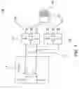
FIG. 1 is a schematic block diagram of a motor drive system;
FIG. 2 is a schematic view of a motor FIG. 1, showing a connection to a pair of inverters; and
FIG. 3 is a graphical representation of common mode noise reduction at different motor winding phase displacement angles and under different module indexes.
DETAILED DESCRIPTION
Reference will now be made to the drawings wherein like reference numerals identify similar structural features or aspects of the subject invention. For purposes of explanation and illustration, and not limitation, a partial view of an exemplary embodiment of a motor drive system in accordance with the invention is shown in FIG. 1 and is designated generally by reference character 100. This disclosure describes techniques to cancel common mode noise and reduce high frequency and low frequency DC ripple current in order minimize the EMI filter and DC link capacitor in a motor controller, and as a result significantly improve the motor drive system power density. The high frequency DC ripple is from the pulse width modulation (PWM) switching ripple, and the low frequency DC ripple is from the third harmonic of the output fundamental frequency.
Other aspects of the motor drive system are provided in FIG. 2, as will be described. The methods and systems of the invention can be used to decrease the overall weight of the system and to decrease common mode noise in the motor drive system.
FIG. 1 shows a motor drive system 100 including a motor 102 including two three-phase winding sets 104, 106, wherein each three-phase winding set 104, 106 is connected to a respective three-phase three-level inverter 108, 110. A common DC link capacitor 112 is connected to both of the three-phase winding sets 108, 110. A common EMI filter 114 is connected to both of the three phase winding sets. The outputs of each of the three-level inverters 108, 1108 are connected to the each set of the three-phase windings of the motor 104,106.
The carrier signals used to generate pulse width modulated gate signals for each of the inverters 108, 110 are phase shifted with respect to each other by 180 degrees. The two sets 104, 106 of the three-phases of the motor are phase shifted with respect to each other by 60 degrees electrically. By displacing the two sets of motor windings by 60 degrees electrically, significant amount of common mode noise can be canceled (ideally completely cancelation) and hence minimize the EMI filter; and by shifting the carrier signals of the two inverters by 180 degrees, up to 80% of the high frequency DC current ripple reduction can be realized and reducing the volume of the DC link capacitor by up to 60%.
A method of limiting common noise in a motor is also disclosed, the method includes driving AC current from a first set three-phase winding set 104 of a motor 102 to a first inverter 108 and driving AC current from a second three-phase winding set 106 of the motor to a second inverter 110 shifted by 180 degrees with respect to the first three-phase winding set 104. If two sets of three phase motor windings are displaced by 60 degrees electrically, and if the rising and falling edges of the inverter switching transients are identical, then common mode noise can be completely canceled and hence eliminate the need for EMI filter. However there is typically some difference in the rising and falling edges of the semiconductor switching waveforms due to intrinsic device characteristics and external parasitics and component parameter mismatches. As a result complete common mode noise cancelation is typically not realistic, but by displacing the motor winding sets by 60 degrees results in significant noise reduction. FIG. 3 shows the common mode noise reduction at different motor winding phase displacement angles and under different module indexes from circuit analysis with realistic switching transients.
Another passive element that contributes significantly to system weight and volume is the DC link capacitor and the high frequency DC ripple current content is a major sizing factor. By shifting the inverter phases signals by 180 degrees the high frequency DC ripple current can be reduced by up to 80%. A 60% capacitor weight reduction is possible by offsetting the carrier signals to the two sets of inverters by 180 degrees. High frequency components, which are sourced through the DC link capacitors, are significantly reduced with the shift in carrier signals.
The methods and systems of the present disclosure, as described above and shown in the drawings, provide for electrical power system with superior properties including increased reliability and efficiency, and reduced size, weight, complexity, and/or cost. While the apparatus and methods of the subject disclosure have been showing and described with reference to embodiments, those skilled in the art will readily appreciate that changes and/or modifications may be made thereto without departing from the spirit and score of the subject disclosure.
Claims
What is claimed is:1. A motor drive system comprising:
a motor including two three-phase winding sets, wherein each three-phase winding set is connected a respective three-phase three-level inverter.
2. The motor drive system of claim 1, wherein a common DC link capacitor connected to both of the three phase winding sets.
3. The motor drive system of claim 1, wherein a common EMI filter connected to both of the three phase winding sets.
4. The motor drive system of claim 1, wherein each of the inverters are phase shifted with respect to each other.
5. The motor drive system of claim 4, wherein each of the inverters are shifted by 180 degrees with respect to each other.
6. The motor drive system of claim 1, wherein two of the three-phases of each motor are phase shifted with respect to a third phase.
7. The motor drive system of claim 6, wherein two of the three-phases of each motor are shifted by 60 degrees with respect to a third phase.
8. A method of driving limiting common noise in a motor comprising:
driving DC current from a first set three-phase winding set of a motor to a first inverter; and
driving DC current from a second three-phase winding set of the motor to a second inverter shifted by 180 degrees with respect to the first three-phase winding set.
9. The method of claim 8, further comprising driving DC current from the first inverter to an EMI filter.
10. The method of claim 9, further comprising driving DC current from the second inverter directly to the EMI filter.
11. The method of claim 9, wherein a falling edge of each of the inverter-switching transients are identical.
12. The method of claim 9, wherein a rising edge of each of the inverter-switching transients are identical.
Images & Drawings included:


Sources:
- United States Patent and Trademark Office - verify current appl. status at the USPTO↗
Recent applications in this class:
- » 20250286494 2025-09-11
SYSTEMS AND METHODS FOR ACTIVE DISCHARGE FOR INVERTER FOR ELECTRIC VEHICLE - » 20250279741 2025-09-04
MOTOR CONTROL METHOD - » 20250266783 2025-08-21
PULSE WIDTH MODULATION AND PHASE SHIFT CONTROL OF A DUAL INVERTER WITH DUAL PROCESSORS - » 20250260351 2025-08-14
PULSED ELECTRIC MACHINE CONTROL - » 20250253794 2025-08-07
FAST DECELERATION OF PMSM AND BLDC MOTORS USING RECIRCULATION BRAKING - » 20250253793 2025-08-07
DRIVE DEVICE - » 20250233540 2025-07-17
SYSTEM FOR GENERATING THERMAL HEAT IN AN ELECTRIC POWER SYSTEM AND AN ELECTRIFIED POWERTRAIN - » 20250219563 2025-07-03
MOTOR CONTROL UNIT, POWERTRAIN, AND ELECTRIC VEHICLE - » 20250219562 2025-07-03
ELECTRIC POWER CONVERSION DEVICE AND AIR CONDITIONER - » 20250192711 2025-06-12
Inverter Control Device, Electric Power Steering System, and Electric Vehicle System
Recent applications for this Assignee:
- » 20250260037 2025-08-14
SYSTEMS AND METHODS FOR ALANE-BASED POWER GENERATION - » 20250250000 2025-08-07
HYDRAULIC DRAG BRAKE - » 20250230772 2025-07-17
MULTI TEMPERATURE GENERATOR AND ENGINE SHARED OIL - » 20250227854 2025-07-10
COVERLAY AS PRINTED CIRCUIT BOARD (PCB) VOLTAGE INSULATOR UNDER CONNECTORS - » 20250226734 2025-07-10
COMPOSITE ROTORS AND METHODS OF MAKING COMPOSITE ROTORS - » 20250224141 2025-07-10
THERMOELECTRIC VORTEX TUBES - » 20250218620 2025-07-03
ISOLATION BARRIER SYSTEMS - » 20250217200 2025-07-03
DECENTRALIZED SCHEDULER OF COMPUTATION JOBS FOR UNSTABLE NETWORK OF HETEROGENOUS NODES - » 20250196039 2025-06-19
FILTER ASSEMBLY - » 20250189500 2025-06-12
AEROSOL DETECTION SYSTEMS