Composite stud wall panel assembly
US20200340244A1
2020-10-29
16/501,524
2019-04-24
✅ Patent granted
US 11,299,886 B2
2022-04-12
-
-
Brian D Mattei | Charissa Ahmad
Cassan MacLean IP Agency Inc.
2039-04-24
Abstract:
A composite stud wall panel assembly, which can be used alone as a blast panel or as a module for wall or roof structures, comprises a frame including a plurality of spaced apart metal studs and metal crossbars interconnecting the studs; and a cementitious aggregate panel, one side of the metal studs being embedded in and permanently connected to the panel along the length of the studs.
Assignee:
- Protectiflex, LLC 1 🇺🇸 Callicoon, NY, United States
Applicant:
Interested in similar patents?
Get notified when new applications in this technology area are published.
Classification:
E04B2/789 » CPC main
Walls, e.g. partitions, for buildings; Wall construction with regard to insulation; Connections specially adapted to walls; Removable non-load-bearing partitions; Partitions with a free upper edge modular coordination with framework or posts of metal characterised by special cross-section of the frame-members as far as important for securing wall panels to a framework with or without the help of cover-strips of open profile of substantially U- or C- section
E04B2/78 IPC
Walls, e.g. partitions, for buildings; Wall construction with regard to insulation; Connections specially adapted to walls; Removable non-load-bearing partitions; Partitions with a free upper edge modular coordination with framework or posts of metal characterised by special cross-section of the frame-members as far as important for securing wall panels to a framework with or without the help of cover-strips
E04B2/74 IPC
Walls, e.g. partitions, for buildings; Wall construction with regard to insulation; Connections specially adapted to walls Removable non-load-bearing partitions; Partitions with a free upper edge modular coordination
E04B2/7409 » CPC further
Walls, e.g. partitions, for buildings; Wall construction with regard to insulation; Connections specially adapted to walls; Removable non-load-bearing partitions; Partitions with a free upper edge modular coordination assembled using frames with infill panels or coverings only; made-up of panels and a support structure incorporating posts special measures for sound or thermal insulation, including fire protection
E04B1/98 » CPC further
Constructions in general; Structures which are not restricted either to walls, e.g. partitions, or floors or ceilings or roofs; Insulation or other protection; Elements or use of specified material therefor; Protection against other undesired influences or dangers against vibrations or shocks ; against mechanical destruction, e.g. by air-raids
E04C5/18 » CPC further
Reinforcing elements, e.g. for concrete; Auxiliary elements therefor; Auxiliary parts for reinforcements, e.g. connectors, spacers, stirrups of metal or substantially of metal
E04B2/60 » CPC further
Walls, e.g. partitions, for buildings; Wall construction with regard to insulation; Connections specially adapted to walls walls of framework or pillarwork Load-bearing ; Walls incorporating load-bearing elongated members with elongated members of metal characterised by special cross-section of the elongated members
Description
FIELD OF THE INVENTION
This invention relates to a composite stud wall assembly.
More specifically, the invention relates to a stud wall assembly, which can be used as protection against blast, ballistic, forced entry, impact, weapons effects, fire and seismic loads. The assembly can be used alone as a blast panel or as a wall or roof panel for modular unit assemblies such as guard booths, trailers and other assemblies for resisting blast, ballistic and/or forced entry loadings.
BACKGROUND OF THE INVENTION
In general, prefabricated blast or building panels are made of reinforced concrete, which is heavy and subject to fragmentation under extreme loads. An object of the present invention is to provide a stud wall panel assembly which is relatively lightweight and provides greater ballistic protection for a given thickness.
SUMMARY OF THE INVENTION
According to one aspect the invention relates to a composite stud wall assembly comprising a frame including a plurality of spaced apart metal studs and metal crossbars interconnecting said studs at locations proximate the ends and at least one location between said ends; and a cementitious aggregate panel, one side of the metal studs being embedded in and permanently connected to the panel along the length of the studs.
BRIEF DESCRIPTION OF THE DRAWINGS
The invention is described in greater detail with reference to the accompanying drawings, which illustrate a preferred embodiment of the invention, and wherein:
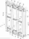
FIG. 1 is an isometric view of a composite stud wall panel assembly as seen from the front and one side in accordance with the invention;
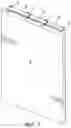
FIG. 2 is an isometric view of the stud wall panel assembly of FIG. 1 and seen from the rear and the other side; and
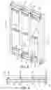
FIG. 3 is a cross section taken generally along line 3-3 of FIG. 2.
DETAILED DESCRIPTION OF THE INVENTION
With reference to the drawings, the composite stud wall assembly includes a frame indicated generally at 1. The frame 1 is defined by a plurality of spaced apart, vertical metal studs 2 partially embedded in a rectangular panel 3 of a composite material. The studs 2 are braced by horizontal metal crossbars 4 extending between the studs 2 and abutting the panel 3. The crossbars 4 can be embedded in the panel 3. The crossbars 4 are located at the centers and proximate the ends of the studs 2. Generally U-shaped metal straps 5 extend between the ends of the studs 2 and are connected thereto by bolts 6 and nuts (not shown). A 0/90°, 1.5×1.5 inch metal or fiber polymer composite mesh 7 reinforcement (FIG. 3) is molded into the panel 3 at mid-depth and tied to the studs 2 by ¼ inch shear studs 8 (FIG. 3).
Preferably the studs 2 are steel C-beams, the crossbars 4 are steel C-beams, and the straps 5 are steel. However, other metals can be used for the studs 2, the crossbars 4 and the straps 5. The panel 3 is formed of rubber pieces with embedded fibers in a cementitious matrix. A preferred embodiment of the material comprises, in a dry state, 25% by weight blended cement, 15% by weight rubber pieces with embedded polymeric macro reinforcing fibers, 50% sand and 10% crushed stone (see Table 1, which also lists the ingredients used to produce the panel).
| TABLE 1 | ||||
| Kg/m3 of Mix | % by dry | |||
| MATERIAL | weight | weight | ||
| Cement (Blended 80:20) | 450 | 25% | |
| Rubber Shred | 272 | 15% | |
| Sand | 877 | 50% | |
| Stone (10 mm crushed | 176 | 10% | |
| aggregate) |
| Total Dry Weight | 1775 | kg. |
| Water | 167 |
| STRUX BT-50 fiber or | 1.18 | kg | ||
| equivalent | ||||
| 3 in 1 Mid Range Water | 1.8 | litres | ||
| Reducer (WRDA ® PN) or | ||||
| equivalent | ||||
| Air Entraining Agent | ||||
| (DAREX AEA ®) or equivalent | ||||
STRUX® BT-50 is a registered trademark for polymeric macro reinforcing fibers, which is included in panels with thicknesses of less than 6 inches. WRDA® PN is a registered trademark for an aqueous solution of polycarboxylate and carbohydrates, and DAREX AEA® is a registered trademark for an aqueous solution of a complex mixture of organic acids. Other reinforcing fibers, water reducers and air entraining agents can be used.
The ingredients can be present in the following percentages by dry weight: cement—20 to 30, rubber—10 to 20, sand—40 to 60 and stone—5 to 15.
The composition of panels used in blast and ballistic testing are listed in Tables 2 and 3.
| TABLE 2 |
| Panel Composition |
| Specific | Percent | Weight in | Volume in | |
| Material | Gravities | by Volume | Pounds | Cubic Feet |
| Rubber | 1.07 | 25.56 | 461 | 6.90 |
| ⅜″ Stone | 2.78 | 6.41 | 299 | 1.73 |
| Sand (UWP) | 2.76 | 31.96 | 1486 | 8.63 |
| Cement | 3.15 | 10.63 | 564 | 2.87 |
| Flyash | 2.28 | 5.14 | 200 | 1.39 |
| Water | 1.00 | 16.77 | 283 | 4.53 |
| Entrapped Air | 3.53 | 0.95 | ||
| TABLE 3 |
| Panel Composition |
| Specific | Percent | Weight in | Volume in | |
| Material | Gravities | by Volume | Pounds | Cubic Feet |
| Rubber | 1.07 | 28.77 | 530 | 7.77 |
| ⅜″ Stone | 2.78 | 3.20 | 150 | 0.86 |
| Sand (UWP) | 2.76 | 31.96 | 1486 | 8.63 |
| Cement | 3.15 | 10.63 | 564 | 2.87 |
| Flyash | 2.28 | 5.14 | 200 | 1.39 |
| Water | 1.00 | 16.77 | 283 | 4.53 |
| Entrapped Air | 3.53 | 0.95 | ||
An eight foot by four foot stud wall panel assembly described above was subjected to blast and ballistic testing. The blast test specimens consisted of four six inch deep vertical cold-formed steel studs 2 (C-beams) embedded in a three inch thick aggregate panel 3 having the composition listed in Table 1. The 0/90 degree, 1.5 inch by 1.5 inch carbon fiber mesh was placed in the panel 3 at mid-depth and tied to the vertical studs 2 using the ¼ inch shear studs 8 spaced twelve inches on center. The vertical studs 2 were braced with horizontal crossbars 4 in the form of 2.5 inch deep steel I-beams located at mid-panel height and approximately ten inches from the top and bottom of the frame. One quarter inch bent steel straps 5 were attached to the top and bottom ends of the studs 2 by two one-half inch diameter bolts 6 on each end and nuts (not shown). The assemblies were connected to steel framing. Ammonium nitrate/fuel oil, a widely used bulk explosive mixture was used as the explosive material to develop blast loads in each test.
Two composite stud wall panel assemblies were subjected to three non-simultaneous explosive shots of the same explosive weight (representative of a car bomb) at varying standoffs. The goal of the three shots was to provide composite panel response data at different blast loading conditions as a means of validating the newly developed blast mitigation composite panel system and to compare the system response to that of conventional wall construction materials utilized in the protective design industry.
In addition, a ballistic resistance testing evaluation of the precast panel assembly was conducted within an indoor range at Oregon Ballistic Laboratories in Salem, Oreg. for various thicknesses of the precast panel in accordance with UL 752 and NIJ-STD-0108.01 testing standards. The muzzle of the test barrel was mounted at selected distances from the target and positioned to produce 0-degree obliquity impacts.
US Army Corps of Engineers Protective Design Center Technical Report PDC-TR 06-08 (Revision 1 dated 7 Jan. 2008—APPROVED FOR PUBLIC RELEASE) describes damage levels and levels of protections (LOPs) that can be used to classify the responses for each test. Table 4 provides descriptions for each component damage level and the corresponding building LOP considering the component as a secondary (i.e., non-load bearing) structural element.
| TABLE 4 |
| Component Damage Level Descriptions per PDC-TR 06-08 |
| Component | Building Level | |
| Damage Level | Description | of Protection * |
| Blowout | Component is overwhelmed by | Below |
| the blast load causing debris | Antiterrorism | |
| with significant velocities. | Standards | |
| Hazardous | Component has failed, and | Very Low (VLLOP) |
| Failure | debris velocities range from | |
| insignificant to very significant. | ||
| Heavy Damage | Component has not failed, but | Low (LLOP) |
| it has significant permanent | ||
| deflections causing it to be | ||
| unrepairable. | ||
| Moderate | Component has some permanent | Medium (MLOP) |
| Damage | deflection. It is generally | |
| repairable, if necessary, | ||
| although replacement may be | ||
| more economic and aesthetic. | ||
| Superficial | Component has no visible | High (HLOP) |
| Damage | permanent damage | |
| * Level of protection corresponding to given damage level for a secondary structural component. |
The results for three blast test, 1-3 using the same quantity of ammonium nitrate/fuel oil (ANFO) representative of a car bomb, at standoffs varying between 40 feet (12.2 m) and 100 feet (30.5 m) are summarized in Table 5.
| TABLE 5 |
| Blast Test Results Summary |
| Positive | |||||
| Charge | Peak | Phase | |||
| Test | Specimen | Standoff | Pressure | Impulse | Post-Test Notes |
| 1 | 1 | 100 ft | 9-10 psi | 49-46 psi-ms | No observable |
| (30.5 m) | (63-70 kPa) | (340-390 kPa-ms) | permanent damage or | ||
| permanent deflection. | |||||
| Response categorized | |||||
| as Superficial Damage/ | |||||
| HLOP | |||||
| 2 | 1 | 60 ft | 28-31 psi | 96-109 psi-ms | Cracking of panel 3 |
| (18.3 m) | (200-215 kPa) | (660-750 kPa-ms) | noted on interior face | ||
| at interface with | |||||
| rightmost vertical stud | |||||
| 2. Minor hairline | |||||
| cracking noted else- | |||||
| where. Minor observed | |||||
| deformation and inden- | |||||
| tations to the vertical | |||||
| and horizontal steel | |||||
| studs 2. Response | |||||
| categorized as Moderate | |||||
| Damage/MLOP) | |||||
| 3 | 2 | 40 ft | 64-93 psi | 153-178 psi-ms | Extensive cracking |
| (12.2 m) | (450-640 kPa) | (1050-1225 kPa-ms) | of panel 3 noted on | ||
| interior face near | |||||
| interface with three | |||||
| rightmost vertical | |||||
| studs 2. Cracking | |||||
| also visible on exterior | |||||
| face of panel 3. A | |||||
| small amount of panel | |||||
| debris projected inward | |||||
| up to 5 feet (1.5 m). | |||||
| Minor observed deforma- | |||||
| tion and indentations | |||||
| to the vertical and | |||||
| horizontal steel studs | |||||
| 2. Response categorized | |||||
| as Heavy Damage/LLOP. | |||||
The ballistic resistance testing evaluation was conducted within an indoor range at the Oregon Ballistic Laboratories for various thicknesses of the precast panel in accordance with UL 752 and NIJ-STD-0108.01 testing standards. The muzzle of the test barrel was mounted at selected distances from the target and positioned to product 0-degree obliquity impacts.
All panel assemblies tested for both ballistic testing standard had overall dimensions of 3 feet (910 mm) wide by 3 feet (910 mm) tall with thickness ranging from 3 inches (76 mm) to 10 inches (254 mm). The two panel composition listed in Tables 2 and 3. For panels with thicknesses less than 6 inches (152 mm), a synthetic macro fiber reinforcement labeled as STRUX BT50® was utilized in the design of the panel assemblies. For panels with thicknesses of 6 inches (152 mm) or greater, carbon-fibre reinforced polymer (C-FRP) rebars labeled as C-BAR® were utilized instead.
Tables 6 and 7 summarize the performance ballistic ratings for the ProtectiFlex precast systems evaluated. Based on the ballistic testing results, a 3-inch (76 mm) thick ProtectiFlex precast panel (as used for the blast-tested composite stud wall system) is rated as UL 752 Level 2 and NIJ-STD-0108.01 Level II.
| TABLE 6 |
| UL 752 Ballistic Rating Summary for |
| the ProtectiFlex Precast Panel System |
| ProtectiFlex | |||
| Specimen | Designated | Thickness | UL 752 Level |
| Number | OBL Number | in (mm) | Rating |
| 1 | 17758 | 3 | (76) | Level 2 |
| 2 | 17761 | 4 | (102) | Level 6 |
| 3 | 17762 | 6 | (152) | Level 8 |
| 5 | 17856 | 10 | (254) | Level 10 |
| 6 | 17760 | 3 | (76) | Level 2 |
| 7 | 17926 | 8 | (203) | Level 9 |
| 8 | 18066 | 8 | (203) | Level 8 |
| 10 | 18067 | 8 | (203) | Level 8 |
| TABLE 7 |
| NIJ-TD-0109.01 Ballistic Rating Summary |
| for the ProtectiFlex Precast Panel System |
| ProtectiFlex | |||
| Specimen | Designated | Thickness | NIJ-STD-0108.01 |
| Number | OBL Number | in (mm) | Level Rating |
| 1 | 17758 | 3 | (76) | Level II |
| 2 | 17761 | 4 | (102) | Level III |
| 3 | 17762 | 6 | (152) | Level IV |
| 4 | 17812 | 8 | (203) | Level IV |
| 5 | 17856 | 10 | (254) | Level IV |
| 6 | 17760 | 3 | (76) | Level II |
| 7 | 17926 | 8 | (203) | Level IV |
Unified Facilities Criteria (UFC) 4-023-7 (dated 7 Jul. 2008 with Change 1 from 1 Feb. 2017—APPROVED FOR PUBLIC RELEASE) provides design guidance to resist direct fire weapons effects. A UL 752 Level 5 rating can be satisfied with approximately 4 inches (102 mm) of reinforced concrete or 8 inches (203 mm) of fully grouted CMU or brick.
As described above, the stud wall panel assembly of the present invention responded with a High Level of Protection (HLOP) at a standoff of 100 feet (30.5 m), a Medium Level of Protection (MLOP) at a standoff of 60 feet (18.3 m), and Low Level of Protection (LLOP) at a standoff of 40 feet (12.2 m) for the same car bomb-sized explosive charge. As a basis of comparison, UFC 4-010-01 presents conventional construction standoff distances (CCSDs) for various common construction types that would be capable of achieving an LLOP for a similarly sized explosive threat (W I). Representative CCSDs for no-load bearing walls are provided in Table 5.
It can be observed that the standoff required to achieve an LLOP for the stud wall panel assembly of the present invention is similar to that of reinforced concrete (26 feet/8 m) and reinforced masonry (30 feet/9 m), noting that the 40-ft (12.2 m) tested standoff is not necessarily an upper limit for LLOP panel response).
With reference to Table 8 below, comparing the minimum wall weights in Table 8 to the 34 psf (160 kg/m2) for the tested panel, the stud wall assembly provides a 60% weight reduction compared to reinforced concrete (based on a 6-inch/150 mm thick wall with 10-psf/50-kg/m2 insulating materials) and a 40% weight reduction compared to reinforced masonry (based on an 8-inch/200-mm thick wall grouted every fourth cell with 10-psf/50-kg/m2 insulating materials). Excluding the insulating materials, these weight reductions are 55% and 28%, respectively. This significant weight reduction for the stud wall assembly can be advantageous in construction to meet non-blast design requirements. In any case, the tested performance of the study wall assembly is a significant improvement over conventional unreinforced masonry or metal stud construction, which would require a standoff of well over 100 feet (30.5 m) to achieve an LLOP. Therefore, the testing stud wall assembly can be considered to be a viable construction option for blast design applications.
| TABLE 8 |
| Conventional Construction Standoff Distances |
| per UFC 4-010-01 for W I Explosive Threat |
| CCSD for LLOP | Minimum Weight | |||
| Conventional Wall | Non-Load | per Unit | ||
| Construction Type | Bearing ft (m) | Area psf (kg/m2) | ||
| Metal Studs w/Brick | 207 | (63) | 45* | (220) | |
| Veneer | |||||
| Metal Studs w/EIFS | 420 | (128) | 11** | (54) | |
| Reinforced Concrete | 26 | (8) | 85** | (415) | |
| Reinforced Masonry | 30 | (9) | 57** | (280) | |
| Unreinforced Masonry | 125 | (38) | 47** | (230) | |
| *Value includes 44 psf (215 kg/m2) for weight of brick veneer. | |||||
| **Value includes 10 psf (50 kg/m2) for weight of EIFS or other insulating materials. |
Claims
1. A composite blast panel assembly comprising:
a frame including a plurality of spaced apart metal studs and metal crossbars interconnecting said studs at locations proximate the ends and at least one location between the ends of the studs: and
a reinforced cementitious aggregate panel, one side of the metal studs being embedded in and permanently connected to the panel along the length of the studs, wherein said reinforced cementitious aggregate panel contains, by dry weight, 20-30% blended cement, 10-20% shredded rubber; 40-60% sand and 5-15% crushed stone.
2. The stud wall assembly of claim 1 including a mesh molded into the panel at mid-depth extending between and connected to the studs.
3. The study wall assembly of claim 2, wherein said mesh is a metal or carbon fiber mesh.
4. The stud wall assembly of claim 2 including shear studs connecting said mesh to the frame studs.
5. The stud wall assembly of claim 1, wherein said frame studs are steel C-beams, and said crossbars are steel C-beams having abutting or embedded in an inner side of the cementitious panel.
6. (canceled)
7. The stud wall assembly of claim 1, wherein said cementitious aggregate panel contains a mixture of 450 kg/m3 of cement, 272 kg/m3 of shredded rubber; 877 kg/m3 of sand and 176 kg/m3 of crushed stone.
Images & Drawings included:
Sources:
- United States Patent and Trademark Office - verify current appl. status at the USPTO↗
Recent applications in this class:
- » 20240141641 2024-05-02
WALL STRUCTURES OF EXTRUDABLE BUILDING MATERIAL - » 20190177973 2019-06-13
PANEL MOUNT FOR SECURING A PANEL TO AN ADJOINING STRUCTURE - » 20130008740 2013-01-10
Sound attenuation stud - » 20120240488 2012-09-27
PROFILED ELEMENT AND METHOD FOR PRODUCING A PROFILED ELEMENT - » 20090113846 2009-05-07
Sheet metal section for dry construction - » 20080250738 2008-10-16
Light weight metal framing member - » 20080159807 2008-07-03
Structural members and joining arrangements therefor - » 20060026911 2006-02-09
Footer track with moisture vent - » 20050166524 2005-08-04
Metal framing member with off site manufactured locking tabs