Circuit arrangement, in particular for an electrically driven motor vehicle
US20210282271A1
2021-09-09
16/328,451
2017-08-31
✅ Patent granted
US 11,617,271 B2
2023-03-28
WO; PCT/EP2017/071906; 20170831
WO; WO2018/041970; 20180308
Briggitte R. Hammond
Manabu Kanesaka
2040-07-28
Abstract:
A circuit arrangement, in particular for an electrically driven motor vehicle
A circuit arrangement (1), in particular for an electrically driven motor vehicle, has at least one bus bar (5) which is connected electrically to a supplier (2) and which is connected to a first consumer (3) at a first transfer point (6) and to a second consumer (4) at a second transfer point (7). Both the first and the second transfer point (6, 7) are formed as flexible contact points.
Inventors:
- Christoph HOYLER 5 🇩🇪 Kirchensittenbach, Germany
- Markus Eichner 3 🇩🇪 Nuernberg, Germany
- Christoph HEUMANN 1 🇩🇪 Nuernberg, Germany
- Alex MUELLER 1 🇩🇪 Nuernberg, Germany
- Markus Eichner 4 🇩🇪 Nuremberg, Germany
- Christoph Heumann 1 🇩🇪 Nuremberg, Germany
- Alex Mueller 1 🇩🇪 Nuremberg, Germany
Assignee:
- Valeo Siemens eAutomotive Germany GmbH 101 🇩🇪 Erlangen, Germany
Applicant:
Interested in similar patents?
Get notified when new applications in this technology area are published.
Classification:
H05K3/326 » CPC main
Apparatus or processes for manufacturing printed circuits; Assembling printed circuits with electric components, e.g. with resistor electrically connecting electric components or wires to printed circuits by abutting or pinching, i.e. without alloying process; mechanical auxiliary parts therefor the printed circuit having integral resilient or deformable parts, e.g. tabs or parts of flexible circuits
H01R12/7064 » CPC further
Structural associations of a plurality of mutually-insulated electrical connecting elements, specially adapted for printed circuits, e.g. printed circuit boards [PCBs], flat or ribbon cables, or like generally planar structures, e.g. terminal strips, terminal blocks; Coupling devices specially adapted for printed circuits, flat or ribbon cables, or like generally planar structures; Terminals specially adapted for contact with, or insertion into, printed circuits, flat or ribbon cables, or like generally planar structures; Coupling devices; Guiding, mounting, polarizing or locking means; Extractors; Locking or fixing a connector to a PCB Press fitting
H01R13/4223 » CPC further
Details of coupling devices of the kinds covered by groups or -; Securing contact members in or to a base or case; Insulating of contact members; Securing in a demountable manner; Securing in resilient one-piece base or case, e.g. by friction ; One-piece base or case formed with resilient locking means comprising integral flexible contact retaining fingers
H05K7/1069 » CPC further
Constructional details common to different types of electric apparatus; Arrangements of circuit components or wiring on supporting structure; Plug-in assemblages of components, e.g. IC sockets having interior leads co-operating by abutting with spring contact pieces
H05K7/1069 » CPC further
Constructional details common to different types of electric apparatus; Arrangements of circuit components or wiring on supporting structure; Plug-in assemblages of components, e.g. IC sockets having interior leads co-operating by abutting with spring contact pieces
H01R2201/26 » CPC further
Connectors or connections adapted for particular applications for vehicles
H05K2201/1059 » CPC further
Indexing scheme relating to printed circuits covered by; Details of components or other objects attached to or integrated in a printed circuit board; Details of mounted components Connections made by press-fit insertion
H05K2201/1059 » CPC further
Indexing scheme relating to printed circuits covered by; Details of components or other objects attached to or integrated in a printed circuit board; Details of mounted components Connections made by press-fit insertion
H05K2201/10272 » CPC further
Indexing scheme relating to printed circuits covered by; Details of components or other objects attached to or integrated in a printed circuit board; Other objects, e.g. metallic pieces Busbars, i.e. thick metal bars mounted on the PCB as high-current conductors
H05K2201/10272 » CPC further
Indexing scheme relating to printed circuits covered by; Details of components or other objects attached to or integrated in a printed circuit board; Other objects, e.g. metallic pieces Busbars, i.e. thick metal bars mounted on the PCB as high-current conductors
H05K3/32 IPC
Apparatus or processes for manufacturing printed circuits; Assembling printed circuits with electric components, e.g. with resistor electrically connecting electric components or wires to printed circuits
H05K3/32 IPC
Apparatus or processes for manufacturing printed circuits; Assembling printed circuits with electric components, e.g. with resistor electrically connecting electric components or wires to printed circuits
H01R12/70 IPC
Structural associations of a plurality of mutually-insulated electrical connecting elements, specially adapted for printed circuits, e.g. printed circuit boards [PCBs], flat or ribbon cables, or like generally planar structures, e.g. terminal strips, terminal blocks; Coupling devices specially adapted for printed circuits, flat or ribbon cables, or like generally planar structures; Terminals specially adapted for contact with, or insertion into, printed circuits, flat or ribbon cables, or like generally planar structures Coupling devices
H01R13/422 IPC
Details of coupling devices of the kinds covered by groups or -; Securing contact members in or to a base or case; Insulating of contact members; Securing in a demountable manner Securing in resilient one-piece base or case, e.g. by friction ; One-piece base or case formed with resilient locking means
H05K7/10 IPC
Constructional details common to different types of electric apparatus; Arrangements of circuit components or wiring on supporting structure Plug-in assemblages of components, e.g. IC sockets
H05K7/10 IPC
Constructional details common to different types of electric apparatus; Arrangements of circuit components or wiring on supporting structure Plug-in assemblages of components, e.g. IC sockets
B60L50/40 » CPC further
Electric propulsion with power supplied within the vehicle using propulsion power supplied by capacitors
Description
Circuit arrangement, in particular for an electrically driven motor vehicle
The invention relates to a circuit arrangement, in particular for an electrically driven motor vehicle.
Typically rigid bus bars are used in circuit arrangements for electrically driven motor vehicles for conducting an electrical current from a supplier to a consumer. In known consumers, for example those embodied. as converters, the electrical contacting for the consumer is accomplished using solder or weld connections or using screw contacts.
The use of such rigid connecting technologies is problematic in cases in which a plurality of components or consumers must be electrically contacted. To maintain component-dependent tolerances, therefore, a discrete bus bar or a discrete pair of bus bars is provided. for each consumer. When there is a large number of consumers to be connected, this approach involves a significant number of components, which leads to increased production costs.
The object of the invention is to provide a circuit arrangement that satisfies requirements for component tolerances to be maintained in a manner that may be realized cost-effectively for serial production.
This object is attained using a circuit arrangement having the additional features of patent claim 1.
Advantageous refinements of the invention are the subject matter of the subordinate claims.
A circuit arrangement, in particular for an electrically driven motor vehicle, has at least one bus bar which is electrically connected to a supplier and which is electrically connected to a first consumer at a first transfer point and to a second consumer at a second transfer point. The first transfer point and the second transfer point are formed as flexible contact points.
Thus multicontacting of the bus bar is suggested such that an electrical current may be supplied to a plurality of consumers. As a result, fewer components are required for supplying electricity so that per unit costs may be reduced. As well, the required tolerances are assured in that no rigid types of connections are used, in particular no soldered, welded, or screw connections are used, for electrically conducting contacting. On the contrary, the contact point is flexible, that is, it is formed, at least in part, from elements that are elastic or bendable such that even a slight movement of bus bar and consumer at the first and/or second transfer point, for example in the context of vibrations and/or shocks due to operation, may be compensated. The permits, first of all, compensation of structurally imposed tolerances, in particular different tolerances, at the first and/or second transfer point while simultaneously using bus bars that are per se rigid. Secondly, the circuit arrangement embodied shock resistant or jolt resistant is particularly suitable for use in electrically driven motor vehicles.
Electrically driven motor vehicles refers to motor vehicles that have at least one electrical drive embodied for driving the motor vehicle. This definition includes in particular so-called hybrid vehicles in which an internal combustion engine is typically provided in addition to the electrical drive.
In a refinement of the invention, a plurality of consumers, that is, more than two consumers, are electrically connected via a bus bar to a number of transfer points corresponding to the number of consumers. Each of the transfer points is formed as a flexible contact point.
The electrically conducting connection is preferably formed at the flexible contact points by means of a force-fit and/or positive-fit connection.
In possible exemplary embodiments, the flexible contact points are formed as press-in contacts and/or spring contacts. Spring contacts may comprise in particular spring contact elements that are resiliently prestressed towards a contact surface that is arranged on a printed circuit board of the first and/or second consumer or on the bus bar. The electrical contacting is thus accomplished by means of a force fit.
Known press-in connections in general have pin-shaped contact parts with deformation zones. For contacting, the contact part is pressed into another, complementary contact part such that a force-fit and positive-fit electrically conducting connection is formed in the region of the deformation zone. The force to be exerted for this is typically several 100 N.
In one possible exemplary embodiment of the invention, at least one of the flexible contact points is formed as a press-in contact that has fork-like contact elements that project from the end of the bus bar and. are pressed into a rigid contact bushing of the first and/or second consumer in a force fit. The fork-like contact elements are flexible and may thus compensate component tolerances and jolting or vibrations.
The fork-like contact elements are particularly preferably flexible such that the force-fit between the fork-like contact elements and the electrically conducting contact bushing may be generated by a press-in force that is less than 100 N, in particular about 30 N to 50 N. In other words, the electrical contacting of the first and/or second consumer may be accomplished with an exertion of force that is clearly less than that used in current press-in techniques.
With spring contacts, the contact element providing the electrically conducting connection is prestressed by a separate spring, for example. In other exemplary embodiments, the contact element itself is formed as a spring contact element and thus has at least one resilient section.
The first and/or second consumer preferably comprises an interconnect device, in particular a printed circuit board having electronic components arranged thereon and interconnected with one another. In one possible exemplary embodiment, the first and/or second consumer implements a control logic for a power electronics element of the motor vehicle.
In the context of the present specification, the supplier is an. element or component that can function as an energy source, at least at times. This definition thus includes conventional sources of current or voltage, such as in particular batteries, but also energy buffers that may be provided, for example, by a capacitor or a plurality of capacitors, in particular a plurality of capacitors switched in parallel.
In one possible exemplary embodiment, the circuit arrangement is part of a control electronics element for a power converter, for example for a frequency converter in an electric motor. Such circuit arrangements are supplied power, for instance, by a direct current intermediate circuit to which power semiconductor modules for the electric motor are also attached. The electric motor is preferably embodied as a drive assembly of an electrically operated motor vehicle. In this case the direct current intermediate circuit is typically supplied power directly from a battery. The direct current intermediate circuit has a capacitor or a plurality of interconnected capacitors, normally called intermediate circuit capacitors, and thus acts as an energy buffer for a downstream power converter, in particular for a downstream power inverter. The first and/or second consumer may also be embodied, for example, as a d.c.-.c. converter that, is supplied power by the intermediate circuit capacitor and draws its power input, of in particular multiple kilowatts, therefrom.
Refer to the exemplary embodiment illustrated in the drawings for further description of the invention.
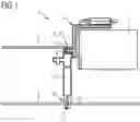
FIG. 1 provides in a schematic side view of a circuit arrangement having a plurality of contacted bus bars, and,
FIG. 2 provides a schematic sectional view with details of the electrical contacting of the bus bars at a first transfer point and a second transfer point.
Equivalent parts are provided with the same reference numbers in all of the figures.
FIG. 1 illustrates the schematic structure of a circuit arrangement 1 that executes, for example, the function of a control module for a power converter with integrated direct current converter. A supplier 2 comprises a battery-supplied direct current intermediate circuit having an intermediate circuit capacitor that provides an energy storage unit for a plurality of electrical networks coupled thereto. The supplier 2 is connected to first and second consumers 3, 4 via two rigid bus bars 5 that are guided, parallel to one another, in a housing 14. In a manner not depicted in greater detail, the first and second consumers 3, 4 comprise a plurality of electronic components arranged on printed circuit boards to which an electrical current may be supplied via the bus bar 5. The first consumer 3 here is an electronic control for a power inverter of an electric motor provided in the drive train of a motor vehicle. The second consumer 4 is a d.c.-d.c. current converter. The bus bars 5 are in electrically conducting contact with the first consumer at first transfer points 6. Correspondingly, the second consumer 4 is in electrically conducting contact at second transfer points 7. Each bus bar therefore has two transfer points 6, 7 for contacting the first and second consumers 3, 4. FIG. 2 illustrates details of the electrical contacting of the bus bar 5 in the region of the first and second transfer points 6, 7.
Both the first and the second transfer points 6, 7 are formed as flexible contact points. At the first transfer point 6, the flexible contact point is realized by a spring contact 11, a butt contact being formed in that a spring contact element 12 reaches through a recess in the housing 14 and contacts a contact surface 8 on the bus bar 5. The spring contact element 12 is provided. on the printed circuit board of the first consumer 3 and is resiliently prestressed towards the contact surface 8. The electrically conducting connection in this case is assured by a force fit between the contact element 12 and the contact surface 8.
The second consumer 4 is connected to the bus bars 5 in an electrically conducting manner via press contacts 9. As depicted in FIG. 2, a sleeve-shaped contact bushing 13 having an electrically conducting inner surface, which is contacted in a force fit and in a positive fit by fork-like contact elements 10, is added to the printed circuit board of the second consumer 4. The fork-like contact elements 10 are flexible and resilient such that, for one thing, operation-related vibrations and component tolerances may be compensated. In addition, the force required to press the contact elements 10 into the contact bushing 13 is significantly less than that required for conventional press-in contacts, in which there is at least some plastic deformation of the contact part during the pressing-in process.
Although the preferred. exemplary embodiment of the invention has been illustrated and described in detail, the invention is not limited. thereby. The person skilled in the art may derive other variations and combinations without departing from essential ideas of the invention.
Claims
1. A circuit arrangement (1), in particular for an electrically driven motor vehicle, having at least one bus bar (5) which is electrically connected to a supplier (2) and which is electrically connected to a first consumer (3) at a first transfer point (6) and to a second consumer (4) at a second transfer point (7), first and second transfer points (6, 7) being formed as flexible contact points.
2. The circuit arrangement (1) according to claim 1, the electrically conducting connection being formed at the flexible contact points by means of a force-fit and/or positive-fit connection.
3. The circuit arrangement (1) according to claim 1 or 2, at least one of the flexible contact points being formed as a press-in contact (11), each press-in contact (11) having fork-like contact elements that project from the end of the bus bar (5) and are pressed in a force-fit into a rigid contact bushing of the first and/or second consumer.
4. The circuit arrangement according to claim 3, the fork-like contact elements being flexible such that the force-fit between the fork-like contact elements and the contact bushing may be produced by a pressing-in force that is less than 100 N, in particular is approximately 30 N to 50 N.
5. The circuit arrangement according to any of claims 1 through 3,
at least one of the flexible contact points being embodied as a spring contact (9).
6. The circuit arrangement (1) according to any of the preceding claims,
the first and/or second consumer (3, 4) comprising an interconnect device, in particular a printed circuit board having electronic components arranged thereon and interconnected with one another.
7. The circuit arrangement (1) according to any of the preceding claims,
the supplier (4) comprising a capacitor, in particular an intermediate circuit capacitor of a direct current intermediate circuit.
Images & Drawings included:


Sources:
- United States Patent and Trademark Office - verify current appl. status at the USPTO↗
Recent applications in this class:
- » 20240130049 2024-04-18
BENDING APPARATUS AND BENDING METHOD USING THE SAME - » 20240114630 2024-04-04
SYSTEMS, METHODS, AND DEVICES FOR PRODUCING INTERCONNECTS ON DEFORMABLE SUBSTRATES OF ELECTRONIC DEVICES - » 20240064909 2024-02-22
LATCHING SYSTEM FOR ESTABLISHING A LATCHING CONNECTION BETWEEN A PRINTED CIRCUIT BOARD AND AN EDGE-CONTACT PLUG, PRINTED CIRCUIT BOARD, EDGE-CONTACT PLUG AND ADD-ON PART - » 20230240019 2023-07-27
Multi head flexible printed circuit ultraviolet laser drilling device and method - » 20230025354 2023-01-26
Method And Apparatus For Singulation Detachment - » 20210251084 2021-08-12
Process for manufacturing a roll of flexible carrier for electronic components - » 20210212216 2021-07-08
Flexible device including conductive traces with enhanced stretchability - » 20210045254 2021-02-11
Loading assembly - » 20210029834 2021-01-28
Flexible circuits for use with gaskets in electronic equipment and related systems and meters - » 20200375036 2020-11-26
METHOD OF ENHANCING ELECTRICAL CONNECTIONS IN 3D-PRINTED OBJECTS
Recent applications for this Assignee:
- » 20230291293 2023-09-14
METHOD FOR PRODUCING AN INTERMEDIATE PRODUCT FOR AN ELECTRICAL MACHINE, COMPRISING A STATOR LAMINATED CORE AND A HOUSING PART, CONNECTED THERETO, OF THE HOUSING - » 20230179052 2023-06-08
Stator for an electric machine, and electric machine - » 20230050543 2023-02-16
COOLING DEVICE FOR SEMICONDUCTOR SWITCHING ELEMENTS, POWER INVERTER DEVICE AND ARRANGEMENT WITH A POWER INVERTER DEVICE AND AN ELECTRIC MACHINE - » 20230026066 2023-01-26
ROTOR FOR AN ELECTRIC MACHINE HAVING A WIDENED FILLING OR VENTING OPENING - » 20230019218 2023-01-19
Control device, inverter, assembly having an inverter and an electrical machine, method for operating an inverter, and computer program - » 20230018069 2023-01-19
STATOR FOR AN ELECTRICAL MACHINE, ELECTRICAL MACHINE, AND VEHICLE - » 20230015579 2023-01-19
Electric device for a converter, converter and arrangement with an electric machine and a converter - » 20230014410 2023-01-19
INVERTER AND ESTIMATION OF AN INTERNAL TEMPERATURE OF A SEMICONDUCTOR SWITCH - » 20230013463 2023-01-19
STATOR HOUSING FOR AN ELECTRICAL MACHINE, ELECTRICAL MACHINE FOR A VEHICLE, AND VEHICLE - » 20230010775 2023-01-12
INVERTER DEVICE, DRIVE DEVICE FOR AN ELECTRICALLY DRIVABLE VEHICLE, AND VEHICLE