Quench-box assembly for hydroprocessing reactors
US20220001341A1
2022-01-06
17/364,182
2021-06-30
✅ Patent granted
US 11,498,038 B2
2022-11-15
-
-
Ellen M McAvoy | Chantel L Graham
Workman Nydegger
2041-06-30
Abstract:
The invention relates to Quench box assembly comprising quench pipe and quench box, to mix quench gas and vapor-liquid effluent from previous catalyst bed to achieve equilibrium temperature before entering the next bed. The quench pipe is in the form of ring having aperture while quench box consists of swirling section and a mixing chamber. The swirling section consists of inclined baffles to provide swirling action to incoming stream and the turbulence created by the swirling action increases the heat transfer rate thus requiring the smaller reactor volume to attain equilibrium temperature. The perforated plate being open from all the sides allowing the liquid to flow uniformly from all directions thus providing uniform distribution on the distributor tray. Hence, eliminates the requirement of rough liquid distributor before the distribution tray.
Inventors:
- Sarvesh Kumar 19 🇮🇳 Faridabad, India
- Gurpreet Singh Kapur 51 🇮🇳 Faridabad, India
- Sankara Sri Venkata RAMAKUMAR 119 🇮🇳 Faridabad, India
- Pravesh KUMAR 6 🇮🇳 Faridabad, India
- Ramesh KARUMANCHI 11 🇮🇳 Faridabad, India
- Madhusudhan Sau 1 🇮🇳 Faridabad, India
Assignee:
- INDIAN OIL CORPORATION LIMITED 195 🇮🇳 Mumbai, India
Applicant:
Interested in similar patents?
Get notified when new applications in this technology area are published.
Classification:
C10G45/00 » CPC further
Hydrotreatment processes
C10G45/00 » CPC further
Refining of hydrocarbon oils using hydrogen or hydrogen-generating compounds
B01F25/4312 » CPC main
Flow mixers; Mixers for falling materials, e.g. solid particles; Static mixers in which the mixing is affected by moving the components jointly in changing directions, e.g. in tubes provided with baffles or obstructions; Mixing tubes, e.g. wherein the material is moved in a radial or partly reversed direction; Straight mixing tubes with baffles or obstructions that do not cause substantial pressure drop; Baffles therefor having different kinds of baffles, e.g. plates alternating with screens
B01F2025/913 » CPC further
Flow mixers; Mixers for falling materials, e.g. solid particles; Direction of flow or arrangement of feed and discharge openings Vortex flow, i.e. flow spiraling in a tangential direction and moving in an axial direction
B01J19/006 » CPC further
Chemical, physical or physico-chemical processes in general; Their relevant apparatus; Details of the reactor Baffles
B01F25/00 IPC
Flow mixers; Mixers for falling materials, e.g. solid particles
B01F25/00 IPC
Mixers
B01J19/0013 » CPC further
Chemical, physical or physico-chemical processes in general; Their relevant apparatus; Controlling or regulating processes Controlling the temperature of the process
B01F2025/916 » CPC further
Flow mixers; Mixers for falling materials, e.g. solid particles; Direction of flow or arrangement of feed and discharge openings Turbulent flow, i.e. every point of the flow moves in a random direction and intermixes
B01F2215/0422 » CPC further
Auxiliary or complementary information in relation with mixing; Technical information in relation with mixing; Numerical information; Geometrical information Numerical values of angles
B01J2219/0077 » CPC further
Chemical, physical or physico-chemical processes in general; Their relevant apparatus; Details of the reactor; Baffles; Baffles attached to the reactor wall inclined
B01J2219/00123 » CPC further
Chemical, physical or physico-chemical processes in general; Their relevant apparatus; Controlling or regulating processes; Controlling the temperature by direct heating or cooling adding a temperature modifying medium to the reactants
B01J19/00 IPC
Chemical, physical or physico-chemical processes in general; Their relevant apparatus
C10G47/00 » CPC further
Cracking of hydrocarbon oils, in the presence of hydrogen or hydrogen- generating compounds, to obtain lower boiling fractions
B01F25/431 IPC
Flow mixers; Mixers for falling materials, e.g. solid particles; Static mixers in which the mixing is affected by moving the components jointly in changing directions, e.g. in tubes provided with baffles or obstructions; Mixing tubes, e.g. wherein the material is moved in a radial or partly reversed direction Straight mixing tubes with baffles or obstructions that do not cause substantial pressure drop; Baffles therefor
B01F23/232 » CPC further
Mixing according to the phases to be mixed, e.g. dispersing or emulsifying; Mixing gases with liquids by introducing gases into liquid media, e.g. for producing aerated liquids using flow-mixing means for introducing the gases, e.g. baffles
Description
FIELD OF THE INVENTION
The present invention covers Quench box assembly comprising quench pipe and quench box for down-flow, three-phase fixed bed hydro-processing reactor is disclosed. The quench pipe is in the form of ring having aperture while quench box consists of swirling section and a mixing chamber.
BACKGROUND OF THE INVENTION
In co-current down-flow reactors the gas and liquid flow downward over the catalyst bed. During reaction the temperature of the reaction mixture increases. To limit the temperature rise in the reactor within permissible limit the reactor is divided into different beds and quench gas followed by mixing device is provided to cool down the effluent before entering into the next bed. The apparatus is located between two catalyst beds. The quench gas and vapor-liquid effluent from catalyst bed gets mixed in the mixing chamber to achieve equilibrium temperature before entering the next bed.
EP0471117A1 covers the quench box assembly having improved mixing efficiency comprises a series of mixing zones: quench fluid inlet zone; quench box mixing zone; a jet stirred mixing zone; and a distributor zone. In the quench fluid inlet zone, quench fluid is introduced to fluid from the catalytic bed above. However, the reaction fluid and quench fluid enter the quench mixing zone through the central opening (16) and no means to mix theses fluids thoroughly is provided. Furthermore, plurality of pipes (22) for introduction of quench gas and process fluid into jet stirred mixing zone, may result into non-uniform temperature from different pipes.
U.S. Pat. No. 7,112,312B2 covers the compact quench box design for a multi-bed, mixed-phase co-current downflow fixed-bed reactor has a quench pipe manifold and nozzle assembly, a collection tray, a mixing chamber, and a single final distributor tray. The quench pipe manifold and nozzle assembly is an annular ring pipe having nozzles arising there from. However, the multiple ramps (50) and mixing chamber (36) for reaction fluid and quench fluid may lead to different temperature in ramps (50) and mixing chamber (36) leading to uneven temperature after the quench-box assembly.
SUMMARY OF THE PRESENT INVENTION
The Quench box assembly disclosed in the present invention is to mix quench gas and vapor-liquid effluent from previous catalyst bed to achieve equilibrium temperature before entering the next bed comprises quench pipe and quench box. The quench pipe is in the form of a ring with apertures for quench gas flow. The quench box consists of a swirling section and a mixing chamber. It provides higher interfacial area and flow path for heat transfer between quench gas and hot reactor effluent. The swirling motion in the swirling section provides better contacting. The weir in the mixing section creates turbulence and helps to attain equilibrium temperature for entire fluid as it is the only passage for fluid flow. Furthermore, the baffle on the plate calms liquid down and provide higher residence time and turbulence for the incoming fluid resulting in higher heat transfer rate. The perforated plate being open from all the sides allowing the liquid to flow uniformly from all directions thus providing uniform distribution on the distributor tray. Hence, eliminates the requirement of rough liquid distributor before the distribution tray.
Objectives of the Present Invention
It is a primary objective of the invention which relates to Quench box assembly comprising quench pipe and quench box for down-flow, three-phase fixed bed hydro-processing reactor.
It is the further objective of the present invention is quench pipe is in the form of ring having aperture while quench box consists of swirling section and a mixing chamber.
Further the object of this invention is that the aforesaid quench box helps to achieve the equilibrium temperature to the hot-reactor effluent and the quench gas entering from the quench pipe.
BRIEF DESCRIPTION OF DRAWINGS
To further clarify advantages and aspects of the invention, a more particular description of the invention will be rendered by reference to specific embodiments thereof, which is illustrated in the appended drawing(s). It is appreciated that the drawing(s) depict only typical embodiments of the invention and are therefore not to be considered limiting of its scope.
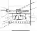
FIG. 1: Schematic view of an exemplary configuration of a prior art hydro-processing reactor.
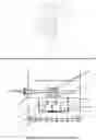
FIG. 2: The design of proposed Quench box in accordance with an embodiment of the present invention.
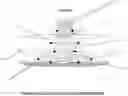
FIG. 3: Fluid motion in the quench box in accordance with an embodiment of the present invention.
DETAILED DESCRIPTION OF THE INVENTION
It should be understood at the outset that although illustrative implementations of the embodiments of the present disclosure are illustrated below, the present invention may be implemented using any number of techniques, whether currently known or in existence. The present disclosure should in no way be limited to the illustrative implementations, drawings, and techniques illustrated below, including the exemplary design and implementation illustrated and described herein.
The terminology and structure employed herein is for describing, teaching and illuminating some embodiments and their specific features and elements and does not limit, restrict or reduce the spirit and scope of the invention.
Unless otherwise defined, all terms, and especially any technical and/or scientific terms, used herein may be taken to have the same meaning as commonly understood by one having an ordinary skill in the art.
-
- Although one or more features and/or elements may be described herein in the context of only a single embodiment, or alternatively in the context of more than one embodiment, or further alternatively in the context of all embodiments, the features and/or elements may instead be provided separately or in any appropriate combination or not at all. Conversely, any features and/or elements described in the context of separate embodiments may alternatively be realized as existing together in the context of a single embodiment.
A commonly used vapor liquid downward flow fixed bed reactor is shown in FIG. 1 (prior art). The gas-liquid mixture enters through a feed pipe 101 and through inlet diffuser 102 gets distributed on the distributer tray 104, having distribution units 105 through catalyst bed 106 installed inside the reactor 103. The hot effluent from the catalyst bed 106 and the quench gas from quench pipe 107 gets mixed in the quench box 108 and flows to the catalyst bed 106/outlet 109. FIG. 1 is a schematic view of an exemplary configuration of a prior art hydro-processing reactor.
The Quench box assembly disclosed in the present invention is to mix quench gas and vapor-liquid effluent from previous catalyst bed to achieve equilibrium temperature before entering the next bed comprises quench pipe and quench box. The quench pipe is in the form of a ring with apertures for quench gas flow. The quench box consists of a swirling section and a mixing chamber. It provides higher interfacial area and flow path for heat transfer between quench gas and hot reactor effluent. The swirling motion in the swirling section provides better contacting. The weir in the mixing section creates turbulence and helps to attain equilibrium temperature for entire fluid as it is the only passage for fluid flow. Furthermore, the baffle on the plate calms liquid down and provide higher residence time and turbulence for the incoming fluid resulting in higher heat transfer rate. The perforated plate being open from all the sides allowing the liquid to flow uniformly from all directions thus providing uniform distribution on the distributor tray. Hence, eliminates the requirement of rough liquid distributor before the distribution tray.
In accordance with the present subject matter, the present invention provides a Quench box assembly for hydro-processing reactors comprising:
a) quench pipe (201) in the form of ring having apertures (202) on its surface; and
b) quench box for down-flow, said quench box comprising swirling section (203) and a gas-liquid mixing chamber (206).
In yet another embodiment, the present invention provides a Quench box assembly, wherein the quench pipe (201) is located around the swirling section (203) of the quench box and the swirling section (203) is having inclined baffles (204) to provide swirling motion to the incoming gas-liquid mixture.
In accordance with the present subject matter, the present invention provides a Quench box assembly, wherein the gas-liquid mixture from the swirling section (203) impinges on the plate (205) and splash around in the mixing chamber (206) and flows downward through the weir (207).
In yet another embodiment, the present invention provides a Quench box assembly, wherein gas-liquid mixture travels from the weir (207) to the perforated plate (208) which is solid at the centre (209) below the weir outlet and having aperture (210) and a baffle in the form of the ring (211).
In accordance with the present subject matter, the present invention provides a Quench box assembly, wherein the perforated plate (208) is open from the sides allowing the liquid to flow uniformly from all directions thus providing uniform distribution on the distributor tray (212).
In yet another embodiment, the present invention provides a Quench box assembly, wherein swirling section (203) is having baffles (204) inclined at an angle preferably between 30 to 60°.
In accordance with the present subject matter, the present invention provides a process for mixing quench gas and vapor-liquid effluent by Quench box assembly, said process comprising:
-
- a) providing swirling motion by swirling section (203) to the incoming fluid from a ring shaped quench pipe (201) having apertures (202); wherein swirling section (203) is having baffles (204) inclined at an angle preferably between 30 to 60°;
- b) impinging the fluid from the swirling section (203) on the plate (205) and splashing around the mixing chamber (206) for obtaining gas-liquid mixture and attaining equilibrium temperature;
- c) flowing the gas-liquid mixture obtained in step (b) through the weir (207) located at the centre of mixing chamber (206) on the perforated plate (208); wherein the plate is solid at the centre (209) below the weir outlet and having aperture (210) and a circular baffle (211);
- d) creating turbulence by the circular baffle (211) and increasing the residence time of the gas-liquid mixture on the plate (208); and
- e) flowing the gas-liquid mixture in downward direction from open sides of plate (208) to distributor plate (new reference).
In accordance with an embodiment of our present invention, design of proposed Quench box is given in FIG. 2. The quench pipe and quench box is shown in FIG. 2. The quench pipe 201 is in the form of circular ring having apertures 202 on its surface and is located around the swirling section 203 of the quench box. The swirling section is having inclined baffles 204 to provide swirling motion to the incoming gas-liquid mixture. The gas-liquid mixture from the swirling section impinges on the plate 205 and splash around in the mixing chamber 206 and flows downward through the weir 207. From the weir 207 it travels to the perforated plate 208 which is solid at the centre 209 below the weir outlet and having aperture 210 and a baffle in the form of the ring 211. The perforated plate 208 is open from the sides allowing the liquid to flow uniformly from all directions thus providing uniform distribution on the distributor tray 212.
According to the main embodiment, the present invention covers Quench box assembly comprising quench pipe and quench box for mixing hot reactor effluent and cold quench gas for down-flow, three-phase fixed bed hydro-processing reactor is disclosed.
In yet another embodiment, FIG. 2 along with FIG. 3 describe Quench box and process in accordance with the present invention. FIG. 3 shows the Fluid motion in accordance with the present invention. In the detailed embodiment of the present invention, the quench pipe (201) is in the form of ring having aperture while quench box consists of swirling section (203) and a mixing chamber (206) and it is located around the swirling section of quench box. The swirling section is having baffles (204) inclined at an angle preferably between 30 to 60° to provide swirling motion to the incoming fluid. The swirling motion provides better contacting between the flowing fluids. The fluid from the swirling section (203) travels to the mixing chamber (206) and impinges on the flat surface and splash around providing the residence time in the mixing chamber (206) for attaining equilibrium temperature. From the mixing chamber (206), gas-liquid mixture flows downward through the weir (207) located at the centre of mixing chamber on the perforated plate (208). The plate is having aperture (210) on its surface except the area at the centre (209) where the incoming liquid from the weir impinges the plate. A circular baffle is provided on the plate for creating turbulence and increase the residence time of fluid on the plate. The plate is having open sides and fluid travels in all direction downward on the distributor plate (212). The design is compact and eliminates the requirement of rough liquid distributor before the distribution tray. It may be noted there is only one passage for the fluid flow thus entire fluid stream will have same temperature. The swirling section (203) with inclined baffles (204) splits the incoming stream into different parts providing high gas liquid interfacial area between the quench-gas and incoming liquid. This will result in better contacting and achieving equilibrium temperature. Furthermore, the turbulence created by the swirling action (203) increases the heat transfer rate thus requiring the smaller reactor volume to attain equilibrium temperature. Furthermore, as there is only one passage for the fluid to pass through the mixing chamber (206) with high velocity, it creates high turbulence inside the mixing chamber resulting in no dead zones inside it. Due to high velocities in mixing chamber there will be no accumulation of solids/fines in the quench box. Hence, the proposed design shows better resistance to fouling. The circular baffle on the perforated plate (208) further increases the residence time of the fluid in the quench box leading to achieve equilibrium temperature. The perforated plate (208) being open from all the sides allowing the liquid to flow uniformly from all directions thus providing uniform distribution on the distributor tray (212). Hence, eliminates the requirement of rough liquid distributor before the distribution tray.
Advantages of the Invention
Therefore, the present invention shows following advantages:
-
- 1. Higher gas-liquid interfacial area for better contacting
- 2. Higher heat transfer rate due to turbulence
- 3. Require less space in the reactor
- 4. No dead zone
- 5. Better resistance to fouling
- 6. Higher residence time to achieve equilibrium temperature.
While specific language has been used to describe the present subject matter, any limitations arising on account thereto, are not intended. As would be apparent to a person in the art, various working modifications may be made to the method in order to implement the inventive concept as taught herein.
Claims
What is claimed is:1. Quench box assembly for hydro-processing reactors comprising:
a) quench pipe in the form of ring having apertures on its surface; and
b) quench box for down-flow, said quench box comprising swirling section and a gas-liquid mixing chamber.
2. The Quench box assembly as claimed in claim 1, wherein the quench pipe is located around the swirling section of the quench box and the swirling section is having inclined baffles to provide swirling motion to the incoming gas-liquid mixture.
3. The Quench box assembly as claimed in claim 2, wherein the gas-liquid mixture from the swirling section impinges on the plate and splash around in the mixing chamber and flows downward through the weir.
4. The Quench box assembly as claimed claim 3, wherein gas-liquid mixture travels from the weir to the perforated plate which is solid at the centre below the weir outlet and having aperture and a baffle in the form of the ring.
5. The Quench box assembly as claimed in claim 4, wherein the perforated plate is open from the sides allowing the liquid to flow uniformly from all directions thus providing uniform distribution on the distributor tray.
6. The Quench box assembly as claimed in claim 2, wherein swirling section is having baffles inclined at an angle preferably between 30 to 60°.
7. The Quench box assembly as claimed in claim 3, wherein swirling section is having baffles inclined at an angle preferably between 30 to 60°.
8. The Quench box assembly as claimed in claim 5 having baffles inclined at an angle preferably between 30 to 60° in the swirling section.
9. Process for mixing quench gas and vapor-liquid effluent by Quench box assembly, said process comprising:
a) providing swirling motion by swirling section to the incoming fluid from previous bed and quench gas from a ring shaped quench pipe having apertures; wherein swirling section is having baffles inclined at an angle preferably between 30 to 60°;
b) impinging the fluid from the swirling section on the plate and splashing around the mixing chamber for obtaining gas-liquid mixture and attaining equilibrium temperature;
c) flowing the gas-liquid mixture obtained in step (b) through the weir located at the centre of mixing chamber on the perforated plate; wherein the plate is solid at the centre below the weir outlet and having aperture and a circular baffle;
d) creating turbulence by the circular baffle and increasing the residence time of the gas-liquid mixture on the plate; and
e) flowing the gas-liquid mixture in downward direction from open sides of plate to distributor plate.
Images & Drawings included:
Sources:
- United States Patent and Trademark Office - verify current appl. status at the USPTO↗
Recent applications in this class:
- » 20200197885 2020-06-25
Feed mixture distribution device - » 20080144433 2008-06-19
Multi-chambered fluid mixing apparatus and method
Recent applications for this Assignee:
- » 20250257272 2025-08-14
PROCESS FOR SYNERGISTIC CO-CONVERSION OF USED OILS TO VALUE ADDED PRODUCTS - » 20250101320 2025-03-27
INTEGRATED STAGING HYDROPROCESSING REACTION VESSEL - » 20240347716 2024-10-17
LITHIUM ION BATTERY ELECTRODES COMPOSITION AND PROCESS OF ITS PREPARATION THEREOF - » 20240343884 2024-10-17
INTEGRATED PROCESS FOR THE PURIFICATION OF LEVULINIC ACID FROM TECHNICAL LIGNIN - » 20240317657 2024-09-26
PROCESS AND A SYSTEM FOR ENHANCING THE YIELD OF LIGHT OLEFINS - » 20240218537 2024-07-04
ENGINEERED ELECTRODE FOR ELECTROBIOCATALYSIS AND PROCESS TO CONSTRUCT THE SAME - » 20240209279 2024-06-27
A MIXED COMPLEX SOAP BASED GREASE COMPOSITION AND METHOD FOR PREPARATION THEREOF - » 20240182797 2024-06-06
INTEGRATED PROCESS FOR PRODUCTION OF CHEMICAL FROM CRUDE OIL USING SLURRY HYDROCRACKING - » 20240182787 2024-06-06
PROCESS FOR PRODUCTION OF NEEDLE COKE AND AROMATICS - » 20240124793 2024-04-18
Additized DME/LPG fuel for improving combustion efficiency