Pole piece retention and insertion method
US20220120248A1
2022-04-21
17/275,488
2019-09-10
✅ Patent granted
US 11,572,858 B2
2023-02-07
WO; PCT/EP2019/074045; 20190910
WO; WO2020/053181; 20200319
Long T Tran | James J Kim
Warner Norcross + Judd LLP
2039-09-10
Abstract:
A fuel injector includes an injector body which accommodates a pole piece of a solenoid actuator. A top portion of the injector body includes a cylindrically formed generally open-ended recessed portion. The recessed portions accommodates a generally cylindrical pole piece, wherein the pole piece includes a bore located along a central axis to provide a fuel flow path. The top portion of the pole piece includes a cylindrically formed recess so as to form a sleeve or lip portion.
Assignee:
- DELPHI AUTOMOTIVE SYSTEMS LUXEMBOURG SA 12 🇱🇺 BASCHARAGE, Luxembourg
Applicant:
Interested in similar patents?
Get notified when new applications in this technology area are published.
Classification:
F02M61/168 » CPC main
Fuel-injectors not provided for in groups - or; Details not provided for in, or of interest apart from, the apparatus of groups - Assembling; Disassembling; Manufacturing; Adjusting
F02M63/0007 » CPC further
Other fuel-injection apparatus having pertinent characteristics not provided for in groups - or ; Details, component parts, or accessories of fuel-injection apparatus, not provided for in, or of interest apart from, the apparatus of groups - or ; Combination of fuel pump with other devices, e.g. lubricating oil pump; Fuel-injection apparatus having a cyclically-operated valve for connecting a pressure source, e.g. constant pressure pump or accumulator, to an injection valve held closed mechanically, e.g. by springs, and automatically opened by fuel pressure using electrically actuated valves
F02M63/00 IPC
Other fuel-injection apparatus having pertinent characteristics not provided for in groups - or ; Details, component parts, or accessories of fuel-injection apparatus, not provided for in, or of interest apart from, the apparatus of groups - or ; Combination of fuel pump with other devices, e.g. lubricating oil pump
F02M2200/8084 » CPC further
Details of fuel-injection apparatus, not otherwise provided for; Fuel injection apparatus manufacture, repair or assembly involving welding or soldering
F02M69/04 IPC
Low-pressure fuel-injection apparatus ; Apparatus with both continuous and intermittent injection; Apparatus injecting different types of fuel Injectors peculiar thereto
F02M61/16 IPC
Fuel-injectors not provided for in groups - or Details not provided for in, or of interest apart from, the apparatus of groups -
Description
TECHNICAL FIELD
This invention relates to fuel injectors and particularly to a pole piece for a fuel injector. It also relates to a method of inserting and fixing a pole piece into a fuel passage of an injector body
BACKGROUND OF THE INVENTION
Typically pole pieces of fuel injectors are press fitted into a recess (providing a fuel passage) in an injector body. One development path to improve (e.g. gasoline engine) fuel injector performance is to increase the system pressure in fuel injectors. This requires high structural resistance of the-injector pressure vessel and as well as structural integrity for the retention of the pole piece which is maintained in position by a press-fit.
This press-fit decreases with the increase of the internal pressure. The interference area of the press-fit cannot be increased more since the insertion force and the material strength limits are finite. The insertion force of the pole piece into the injector body has to be limited, and pole piece retention has to be ensured under pressure with a material with weaker mechanical properties but with higher magnetic performance.
Any welding process to assembly the pole piece to the upper housing generates the weakest point of the injector in regards to the internal pressure.
It is an object of the invention to provide a design and method of pole piece retention which allows increased pressure application and which also overcomes the aforementioned problems.
SUMMARY OF THE INVENTION
In one aspect is provided A fuel injector including an injector body adapted to accommodate a pole piece of a solenoid actuator, where the top portion of said injector body includes a cylindrically formed generally open-ended recessed portion, said recessed portions accommodating a generally cylindrical pole piece, wherein said pole piece includes a bore located along the central axis to provide a fuel flow path, and the top portion of said pole piece includes a cylindrically formed recess so as to form a sleeve or lip portion.
A distal portion of said lip or sleeve portion may protrude from the top end of the injector body.
The fuel injector may including upper housing, the distal end of which is in contact with the upper end of the injector body and a distal portion of said lip or sleeve portion.
The fuel injector may include a weld formed at the junction of distal end of the upper housing, with the upper end of the injector body and a distal portion of said lip or sleeve portion.
Said weld may join at least three of the following: distal end of the upper housing, upper end of the injector body and a distal portion of said lip or sleeve portion.
The outer diameter (OD) of the pole piece sleeve (and inner diameter (ID) of the pole piece sleeve may be dimensions such that:
0 . 7 < ID OD < 0 . 9 9
The length (thickness) of the lip (L) and the pole piece sleeve outer diameter OD may be dimensioned such that:
0 . 1 < L OD < 0 . 5
BRIEF DESCRIPTION OF THE DRAWINGS
The present invention is now described by way of example with reference to the accompanying drawings in which:
FIG. 1 shows a current known design showing the schematically the top portion of a solenoid operated fuel injector.
FIG. 2 shows an arrangement according to one aspect;
FIG. 3 shows the salient portion of FIG. 2 in more detail.
DESCRIPTION OF THE PREFERRED EMBODIMENTS
FIG. 1 shows a current known design showing the schematically the top portion of a solenoid operated fuel injector.
An injector outer housing 1 contains an injector body 2. The injector body is in the form of a generally hollow cylindrical housing has generally a closed upper end and contains the pole piece. The pole piece 3 comprises a generally cylindrical body and along the longitudinal central axis thereof is formed a fuel flow channel i.e. an internal fuel passage. An electrical connector piece 4 provides electrical connection and terminals. An upper housing 5 is fitted onto the arrangement as shown.
The welding 6 is performed around/at the bottom (rim) portion and the top of the injector body after the pole piece is press fitted.
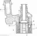
FIG. 2 shows an arrangement according to one aspect which shows the pole piece/upper housing/injector body assembly. The same components have generally the same components as FIG. 1. Here the injector body 22 is formed open ended at the top. The pole piece 3 is fitted i.e. inserted into this open end. The weld portion has reference numeral 10.
FIG. 3 shows the salient portion in more detail.
The pole piece at the upper end has a sleeved portion 7 defining a circumferential rim or lip portion 8. At the bottom of the recess the fluid passage 9 is provided, and so a shoulder portion is formed.
The pole piece sleeve forming the relatively long thin (circumferential) lip provides two functions: It is used as a backup lip for the welding to prevent weld splatters and by appropriate dimensioning, stresses are minimized in the area improving significantly the pressure strength of the injector pressure vessel, formed by the injector body and arrangement shown
Welding is performed through the upper housing and the injector body and partially through the pole piece maintaining the three components in a tight assembly. The weld region is shown with reference numeral 10.
The inner diameter of the sleeve (ID) must be as close as possible to the outer diameter (OD) to prevent high difference of area. The lip length L must be sufficient to allow a “smooth stiffness transition” between the assemble components.
The arrangement provides a decrease of the stress of the assembly under pressure while ensuring the retention of the pole piece through the weld.
Preferably the range of the parameters can be defined as follow:
0 . 7 < ID OD < 0 . 9 9 0 . 1 < L OD < 0 . 5
Where OD is the pole piece outer diameter, ID is the pole piece inner diameter, and L is the lip length defined between the center of the weld and the flat surface of the pole piece.
Claims
1-6. (canceled)
7. A fuel injector comprising:
an upper housing; and
an injector body which accommodates a pole piece of a solenoid actuator, where a top portion of said injector body includes a cylindrically formed open-ended recessed portion, said recessed portion accommodating a cylindrical pole piece, wherein said pole piece includes a bore located along a central axis which provides a fuel flow path and a top portion of said pole piece includes a cylindrically formed recess so as to form a sleeve or lip portion; wherein a weld is formed at a junction of a distal end of the upper housing, an upper end of the injector body, and a distal portion of said lip or sleeve portion.
8. A fuel injector as claimed in claim 7, wherein the distal portion of said lip or sleeve portion protrudes from a top end of the injector body.
9. A fuel injector as claimed in claim 7, wherein the distal end of the upper housing is in contact with the upper end of the injector body and the distal portion of said lip or sleeve portion.
10. A fuel injector as claimed in claim 7, wherein said weld joins at least two of the following: the distal end of the upper housing, the upper end of the injector body, and the distal portion of said lip or sleeve portion.
11. A fuel injector as claimed in claim 1, wherein an outer diameter (OD) of the sleeve or lip portion and an inner diameter (ID) of the sleeve or lip portion are dimensioned such that:
0 . 7 < ID OD < 0 . 9 9
12. A fuel injector as claimed in claim 1, wherein a thickness (L) of the sleeve or lip portion and an outer diameter (OD) of the sleeve or lip portion are dimensioned such that:
0 . 1 < L OD < 0 . 5
Images & Drawings included:


Sources:
- United States Patent and Trademark Office - verify current appl. status at the USPTO↗
Recent applications in this class:
- » 20250027471 2025-01-23
METHOD FOR PRODUCING A PINTLE FOR A FUEL INJECTOR - » 20240229752 2024-07-11
Fuel injectors with misalignment compensation - » 20240084770 2024-03-14
METHOD AND APPARATUS FOR HARD MACHINING ORIFICES IN FUEL SYSTEM AND ENGINE COMPONENTS - » 20240060465 2024-02-22
FUEL INJECTOR - » 20230243326 2023-08-03
Coupling Body, Fuel Injection Valve Including Coupling Body, and Method for Manufacturing Coupling Body - » 20210363953 2021-11-25
Fuel flow passage member and fuel injection valve including the same - » 20210348584 2021-11-11
Nozzle for injecting fuel - » 20210317807 2021-10-14
METHOD FOR PRODUCING A NOZZLE - » 20210140399 2021-05-13
Fuel injector valve seat assembly including insert locating and retention features - » 20200232435 2020-07-23
Injector alignment apparatus and methods of use thereof
Recent applications for this Assignee:
- » 20220255472 2022-08-11
Method of controlling braking of an multi-phase electrical motor - » 20220236143 2022-07-28
Method of determining acceleration of a crankshaft - » 20210148297 2021-05-20
Method of controlling a fuel injector - » 20210095626 2021-04-01
High pressure fuel pump - » 20200373861 2020-11-26
Method of controlling a brushless DC motor - » 20190383205 2019-12-19
Method to determine the use of a block heater - » 20190301422 2019-10-03
Method and apparatus to control an ignition system - » 20190145365 2019-05-16
Fuel pump - » 20170219456 2017-08-03
Method and apparatus for leak detection - » 20160346732 2016-12-01
Method of controlling a multi selective catalytic reduction system