BATTERY PACK STRUCTURE
US20250246719A1
2025-07-31
18/921,002
2024-10-21
Smart Summary: A battery pack structure has two parts stacked on top of each other. The first part contains a battery module made up of several battery cells, all enclosed in a case with a cover on top. The second part, located below the first, also has a battery module with its own set of battery cells in a separate case, sealed with a cover on the bottom. This design helps to organize and protect the battery cells efficiently. Overall, it allows for better use of space while keeping the batteries secure. 🚀 TL;DR
Abstract:
The battery pack structure includes: a first battery pack in which a first battery module including a plurality of stacked battery cells is housed in a first case and a first cover that seals the first case from above; and a second battery pack located below the first battery pack, wherein a second battery module including a plurality of stacked battery cells is housed in a second case and a second cover that seals the second case from below.
Assignee:
- TOYOTA JIDOSHA KABUSHIKI KAISHA 24,739 🇯🇵 Toyota-shi, Japan
Applicant:
Interested in similar patents?
Get notified when new applications in this technology area are published.
Classification:
H01M10/6568 » CPC main
Secondary cells; Manufacture thereof; Heating or cooling; Temperature control; Means for temperature control structurally associated with the cells characterised by the type of heat-exchange fluid; Liquids characterised by flow circuits, e.g. loops, located externally to the cells or cell casings
H01M10/613 » CPC further
Secondary cells; Manufacture thereof; Heating or cooling; Temperature control; Types of temperature control Cooling or keeping cold
H01M50/204 » CPC further
Constructional details or processes of manufacture of the non-active parts of electrochemical cells other than fuel cells, e.g. hybrid cells; Mountings; Secondary casings or frames; Racks, modules or packs; Suspension devices; Shock absorbers; Transport or carrying devices; Holders Racks, modules or packs for multiple batteries or multiple cells
H01M50/271 » CPC further
Constructional details or processes of manufacture of the non-active parts of electrochemical cells other than fuel cells, e.g. hybrid cells; Mountings; Secondary casings or frames; Racks, modules or packs; Suspension devices; Shock absorbers; Transport or carrying devices; Holders Lids or covers for the racks or secondary casings
Description
CROSS-REFERENCE TO RELATED APPLICATION
This application claims priority to Japanese Patent Application No. 2024-009508 filed on Jan. 25, 2024, incorporated herein by reference in its entirety.
BACKGROUND
1. Technical Field
The present disclosure relates to a battery pack structure.
2. Description of Related Art
Japanese Unexamined Patent Application Publication No. 2015-115285 (JP 2015-115285 A) discloses a power supply device in which battery packs are stacked vertically in such a posture that top surfaces of the battery packs face each other.
SUMMARY
In the power supply device of JP 2015-115285 A, a passage in which a heat exchange medium passes is provided on a lower end surface, and there is a risk that a liquid leakage occurs and causes a short circuit at a time of interference from a passage surface side.
Moreover, in the power supply device of JP 2015-115285 A, the passage in which the heat exchange medium passes, and a discharge route of gas generated from each of the battery packs, are provided on both upper and lower end surfaces, and a package efficiency is not good.
The present disclosure has been made in view of the matters, and an objective of the present disclose is to provide a battery pack structure that suppresses a short circuit at a time of interference and has a good package efficiency.
A battery pack structure relating to the present disclosure includes a first battery pack in which a first battery module constituted of a plurality of stacked battery cells is stored in a first case and a first cover that seals the first case from above, and a second battery pack in which a second battery module positioned below the first battery pack and constituted of a plurality of stacked battery cells is stored in a second case and a second cover that seals the second case from below.
According to the present disclosure, a battery pack structure can be realized that suppresses a short circuit at a time of interference and has a good package efficiency.
BRIEF DESCRIPTION OF THE DRAWINGS
Features, advantages, and technical and industrial significance of exemplary embodiments of the disclosure will be described below with reference to the accompanying drawings, in which like signs denote like elements, and wherein:
FIG. 1 is a schematic configuration diagram of a battery pack structure according to an embodiment; and
FIG. 2 is a configuration diagram of a battery pack structure according to an example.
DETAILED DESCRIPTION OF EMBODIMENTS
A battery pack structure according to an embodiment of the present disclosure will be described with reference to the drawings. Incidentally, the constituent elements in the following embodiments include those that can be easily replaced by a person skilled in the art or those that are substantially the same.
Embodiment
FIG. 1 is a schematic configuration diagram of a battery pack structure according to an embodiment. UPR shown in FIG. 1 represents the upper part of the vehicle on which the battery pack structure 1 is mounted, and RH represents the right side of the vehicle on which the battery pack structure 1 is mounted. The battery pack structure 1 includes a first battery pack 2, a second battery pack 3 positioned below the first battery pack 2, and a cooler 4 disposed between the first battery pack 2 and the second battery pack 3.
The first battery pack 2 includes three first battery modules 21 arranged in the horizontal direction, a first case 22, and a first cover 23. The first battery modules 21 are accommodated in the first case 22 and the first cover 23 that seals the first case 22 from above so that the upper side faces upward of the vehicle. However, the number and orientation of the first battery modules 21 are not particularly limited.
The second battery pack 3 includes three second battery modules 31 arranged in the horizontal direction, a second case 32, and a second cover 33. The second battery modules 31 are housed in the second case 32 and the second cover 33 that seals the second case 32 from below so that the upper side faces downward of the vehicle. However, the number and orientation of the second battery modules 31 are not particularly limited.
The first battery modules 21 and the second battery modules 31 are each composed of a plurality of stacked battery cells, and an electrode body accommodated in the battery cells includes a solid electrolyte.
The first case 22 and the second case 32 are made of the same material and have the same shape, and are arranged such that the opening portions are located on opposite sides of each other.
The rigidity of the second cover 33 is greater than the rigidity of the first cover 23. Specifically, the first cover 23 and the second cover 33 are designed to have different materials and plate thicknesses, and thereby have predetermined rigidity.
The distance L2 between the second cover 33 and the second battery module 31 is larger than the distance L1 between the first cover 23 and the first battery module 21. As an example, the distance L2 between the second cover 33 and the second battery module 31 is 20 mm, and the distance L1 between the first cover 23 and the first battery module 21 is 7 mm.
The cooler 4 cools the first battery modules 21 and the second battery modules 31 with a cooling liquid.
According to the embodiment described above, since the flow path of the cooling liquid is not disposed on the lower end surface of the battery pack structure 1, it is prevented that the liquid leaks and short-circuits occur at the time of interference from the road surface side.
Further, according to the embodiment, the second cover 33 has a large stiffness and a large distance L2 between the second cover 33 and the second battery module 31, and this space serves as an energy absorption (EA) space. Therefore, it is possible to prevent a short circuit due to the occurrence of liquid leakage at the time of interference from the road surface side.
Further, according to the embodiment, since the cooler 4 is disposed outside the first battery pack 2 and the second battery pack 3, even if liquid leakage occurs during interference, it is difficult for the liquid to enter the inside of the first battery pack 2 and the second battery pack 3.
Further, according to the embodiment, since the cooler 4 is disposed between the first battery pack 2 and the second battery pack 3, the package efficiency is high.
Further, according to the embodiment, the second cover 33 has a large rigidity and a large distance L2 between the second cover 33 and the second battery module 31, and this space functions as a flue gas space.
Further, according to the embodiment, since the rigidity of the first cover 23 is small, the first cover 23 is deformed due to interference from the outside, and a flue gas space is secured, so that the package efficiency is improved.
Further, according to the embodiment, since the first case 22 and the second case 32 are the same member made of the same material and having the same shape, it is possible to restrain an increase in the number of types of components.
EXAMPLE
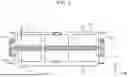
FIG. 2 is a configuration diagram of a battery pack structure according to an example. As shown in FIG. 2, the battery pack structure 1 described in the embodiment can be realized.
Further advantages and variations can be readily derived by one of ordinary skill in the art. Thus, the broader aspects of the disclosure are not limited to the specific details and representative embodiments presented and described above. Accordingly, various modifications may be made without departing from the spirit or scope of the general inventive concept as defined by the appended claims and their equivalents.
Claims
What is claimed is:1. A battery pack structure comprising:
a first battery pack in which a first battery module constituted of a plurality of stacked battery cells is stored in a first case and a first cover that seals the first case from above; and
a second battery pack in which a second battery module positioned below the first battery pack and constituted of a plurality of stacked battery cells is stored in a second case and a second cover that seals the second case from below.
2. The battery pack structure according to claim 1, further comprising a cooler that cools the first battery module and the second battery module, the cooler being disposed between the first battery pack and the second battery pack.
3. The battery pack structure according to claim 1, wherein rigidity of the second cover is greater than rigidity of the first cover.
4. The battery pack structure according to claim 1, wherein the first case and the second case are made of a same material and have a same shape, the first case and the second case being disposed such that an opening portion of the first case and an opening portion of the second case are positioned on opposite sides from each other.
5. The battery pack structure according to claim 1, wherein a distance between the second cover and the second battery module is greater than a distance between the first cover and the first battery module.
Images & Drawings included:


Sources:
- United States Patent and Trademark Office - verify current appl. status at the USPTO↗
Similar patent applications:
- » 20190140231
BATTERY PACK FIXING STRUCTURE AND BATTERY PACK REPLACING APPARATUS - » 20250079598
BATTERY PACK WATERPROOF STRUCTURE AND BATTERY PACK - » 20190184831
Vehicle battery pack protective structure and vehicle having the vehicle battery pack protective structure - » 20250079755
BATTERY PACK CONNECTOR WATERPROOF STRUCTURE AND BATTERY PACK - » 20130004821
Electrical connection structure for increasing the securing reliability and method of manufacturing the same, and battery pack structure - » 20130177795
Swappable, configurable and structural battery pack for electric vehicles - » 20100112424
BATTERY PACK STRUCTURE - » 20140072835
Battery pack structure for electric vehicles - » 20080096072
Battery pack structure with heater - » 20120090907
Vehicle with structural battery pack
Recent applications in this class:
- » 20250246718 2025-07-31
THERMAL MANAGEMENT SYSTEMS FOR MANAGING BOTH CONVECTIVE AND CONDUCTIVE HEAT TRANSFER WITHIN TRACTION BATTERY PACKS - » 20250219195 2025-07-03
BATTERY PACK AND BATTERY SYSTEM THEREOF - » 20250210757 2025-06-26
BATTERY ASSEMBLY AND CONTROLLING METHOD OF THE SAME - » 20250210756 2025-06-26
IMMERSED COOLED BATTERY MODULE - » 20250201969 2025-06-19
BATTERY TEMPERATURE REGULATION DEVICE, VEHICLE, AND METHOD FOR PRODUCING A BATTERY TEMPERATURE REGULATION DEVICE - » 20250201968 2025-06-19
BATTERY CELL HOLDER FOR THERMAL MANAGEMENT OF A PLURALITY OF BATTERY CELLS - » 20250201967 2025-06-19
EXPANSION TANK AND BATTERY COOLING SYSTEM - » 20250201966 2025-06-19
IMMERSION THERMAL MANAGEMENT SYSTEMS FOR TRACTION BATTERY PACKS - » 20250192280 2025-06-12
BATTERY PACK FOR AN ELECTRIC ROAD VEHICLE AND METHOD FOR THE COMPENSATION OF THE THICKNESS VARIATION OF AN ELECTROCHEMICAL CELL FOR SAID BATTERY PACK - » 20250192279 2025-06-12
TEMPERATURE CONTROL DEVICE, IN PARTICULAR COOLING DEVICE FOR A MOTOR VEHICLE
Recent applications for this Assignee:
- » 20250247795 2025-07-31
IN-VEHICLE COMMUNICATION DEVICE, COMMUNICATION CONTROL METHOD, AND NON-TRANSITORY STORAGE MEDIUM - » 20250246929 2025-07-31
REDUNDANT POWER SUPPLY SYSTEM - » 20250246745 2025-07-31
BATTERY PACK - » 20250246738 2025-07-31
HOUSING APPARATUS - » 20250246734 2025-07-31
BATTERY PACK - » 20250246706 2025-07-31
BATTERY TEMPERATURE ADJUSTMENT SYSTEM AND BATTERY TEMPERATURE ADJUSTMENT METHOD - » 20250246705 2025-07-31
POWER STORAGE DEVICE - » 20250246656 2025-07-31
FUEL CELL SYSTEM - » 20250246653 2025-07-31
FUEL CELL SYSTEM - » 20250246637 2025-07-31
ANODE CURRENT COLLECTOR, ANODE, AND LITHIUM-METAL SECONDARY BATTERY