BATTERY PACK
US20250246734A1
2025-07-31
18/999,099
2024-12-23
Smart Summary: A battery pack is made up of several battery cells stacked on top of each other. There is a frame at the top and another frame at the bottom to hold everything together. The top frame has a special part that adds strength and runs across the battery cells. This strong part also overlaps with the bottom frame for extra support. Overall, the design helps keep the battery cells secure and stable. 🚀 TL;DR
Abstract:
A battery pack includes: a plurality of battery cells stacked in a predetermined direction; an upper frame member disposed above the battery cell; and a lower frame member disposed below the battery cell. Further, the upper frame member includes a reinforcing member extending in a direction perpendicular to a stacking direction of the battery cells, and at least a part of the reinforcing member overlaps the lower frame member.
Assignee:
- TOYOTA JIDOSHA KABUSHIKI KAISHA 24,739 🇯🇵 Toyota-shi, Japan
Applicant:
Interested in similar patents?
Get notified when new applications in this technology area are published.
Classification:
H01M50/233 » CPC main
Constructional details or processes of manufacture of the non-active parts of electrochemical cells other than fuel cells, e.g. hybrid cells; Mountings; Secondary casings or frames; Racks, modules or packs; Suspension devices; Shock absorbers; Transport or carrying devices; Holders characterised by physical properties of casings or racks, e.g. dimensions
H01M50/209 » CPC further
Constructional details or processes of manufacture of the non-active parts of electrochemical cells other than fuel cells, e.g. hybrid cells; Mountings; Secondary casings or frames; Racks, modules or packs; Suspension devices; Shock absorbers; Transport or carrying devices; Holders; Racks, modules or packs for multiple batteries or multiple cells characterised by their shape adapted for prismatic or rectangular cells
Description
CROSS-REFERENCE TO RELATED APPLICATION(S)
The present application claims priority to and incorporates by reference the entire contents of Japanese Patent Application No. 2024-010426 filed in Japan on Jan. 26, 2024.
BACKGROUND
The present disclosure relates to a battery pack.
Japanese Laid-open Patent Publication No. 2015-137008 discloses the structure with improved maintainability, in which, the under cover disposed below the battery pack is fastened to the battery pack and is provided with a cover piece not covering the battery fastening position from below.
A frame member is disposed between each battery cell of the battery pack. In such a battery pack, in the portion where the battery cells are arranged on both sides of the frame member, for example, when the side thrust load from the outside is input, the load input through the frame member, evenly in the battery cells on both sides It will be carried.
SUMMARY
There is a need for providing a battery pack capable of suppressing buckling of the frame member.
According to an embodiment, a battery pack includes: a plurality of battery cells stacked in a predetermined direction; an upper frame member disposed above the battery cell; and a lower frame member disposed below the battery cell. Further, the upper frame member includes a reinforcing member extending in a direction perpendicular to a stacking direction of the battery cells, and at least a part of the reinforcing member overlaps the lower frame member.
BRIEF DESCRIPTION OF THE DRAWINGS
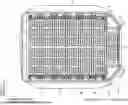
FIG. 1 is a plan view illustrating a configuration of a battery pack according to an embodiment;
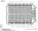
FIG. 2 is an enlarged plan view of the X portion of the battery pack of FIG. 1;
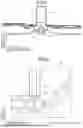
FIG. 3 is a cross-sectional view illustrating a condition in which the battery pack of FIG. 2 is cut at a position of A-A line;
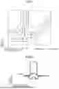
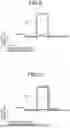
FIG. 4 is a cross-sectional view illustrating a related-art battery pack that is cut at the same position as A-A line of FIG. 2;
FIG. 5 is a cross-sectional view illustrating a condition in which the battery pack of FIG. 2 is cut at the position of B-B line;
FIG. 6 is a plan view illustrating the configuration of a related-art battery pack;
FIG. 7 is a plan view illustrating a configuration of a battery pack according to an embodiment;
FIG. 8 is a cross-sectional view illustrating a condition in which the battery pack of FIG. 6 is cut at the position of C-C line;
FIG. 9 is a cross-sectional view illustrating a condition in which the battery pack of FIG. 6 is cut at the position of D-D line; and
FIG. 10 is a cross-sectional view illustrating a condition in which a battery pack of FIG. 7 is cut at a position of E-E line.
DETAILED DESCRIPTION
In the related art, in the battery cell disposed at the most end of the battery pack, that is, in a portion in which the battery cell is disposed only on one side of the frame (skeleton) member, for example, when a side thrust load is input from the outside, the load input through the frame member will be carried by only one side of the battery cell. Therefore, at the time of input of the side collision load, the frame member is buckled in the direction in which the battery cell is not disposed (“<” shaped folding), there is a possibility that an excessive load is input to the battery cell.
A battery pack according to an embodiment of the present disclosure will be described with reference to the drawings. In addition, components in the following embodiments include those which can be substituted and easily by those skilled in the art, or those which are substantially the same.
The battery packs according to the embodiment, is used as a battery of a vehicle such as, but not limited to, a Hybrid Electric Vehicle (HEV), a Plug-in Hybrid Electric Vehicle (PHEV), and a Battery Electric Vehicle (BEV).
FIG. 1 illustrates a state of removing the upper cover (lid member) from the battery pack according to the embodiment. Further, FIG. 2 illustrates an enlarged state of the X portion of the battery pack in FIG. 1. Further, FIG. 3 illustrates the battery pack in FIG. 2 cut at the state of A-A line.
The battery pack 1 includes a lower case (housing member) 11, a plurality of battery cells 12, a plurality of upper frame member 13, a reinforcing member 14, a plurality of lower frame member 15, a share panel 16, and a connecting member 18.
The lower case 11 is for accommodating each member of the battery pack 1. The battery cells 12 are, for example, liquid-based batteries such as lithium-ion secondary batteries. The battery cells 12 constitute a battery module by being stacked in the length direction of the battery pack 1.
The upper frame member 13 is a member constituting a frame in the lower case 11. The upper frame member 13 is a rod-shaped member extending in the width direction of the battery pack 1 as illustrated in FIG. 1. The upper frame member 13 is disposed above the battery pack 1 in the height direction with respect to the battery cell 12. Incidentally, “the height direction of the battery pack 1” indicates a direction (the thickness direction of the battery pack 1) perpendicular to the length direction and the width direction of the battery pack 1 illustrated in FIG. 1.
Further, the upper frame member 13, as illustrated in FIGS. 1 and 2, in the stacking direction of the battery cell 12 (the length direction of the battery pack 1), is provided on the side surface of the plurality of battery cells 12. The upper frame member 13, as illustrated in FIG. 2, is provided with a reinforcing member 14.
The reinforcing member 14 is for reinforcing the upper frame member 13. The reinforcing member 14, as illustrated in FIG. 2, extends in a direction perpendicular to the stacking direction of the battery cell 12 (the length direction of the battery pack 1), i.e. the width direction of the battery pack 1. Further, the reinforcing member 14, in the stacking direction of the battery cell 12 is provided on the outside of the battery cell 12 disposed at the most end. Note that “the battery cell 12 disposed at the most end” indicates the battery cell 12 disposed at the most rear side of the vehicle, as illustrated in FIG. 2. That is, the “battery cell 12 disposed at the most end” indicates a battery cell 12 in which the other battery cell 12 is disposed only on one side (left side in FIG. 2) and the other battery cell 12 is not disposed on the opposite side (right side in FIG. 2).
Further, as illustrated in the Y portion of FIG. 3, the reinforcing member 14 at least partially wraps with the lower frame member 15. Note that “the reinforcing member 14 and the lower frame member 15 lap” indicates that the reinforcing member 14 and the lower frame member 15 overlap in the height direction of the battery pack 1.
Here, the related-art battery pack 101, as illustrated in FIG. 4, is not provided with a reinforcing member 14, the connecting member 18 is provided at a position corresponding to the reinforcing member 14. Then, the connecting member 18 is not wrapped with the lower frame member 15. Therefore, for example, when the side thrust load is input from the outside, as illustrated by the Z portion in FIG. 4, the gap portion between the connecting member 18 and the lower frame member 15 becomes weak portion (fracture start point), there is a possibility that the upper frame member 13 is buckled.
On the other hand, in the battery pack 1 according to the embodiment, as illustrated in the Y portion of FIG. 3, at least a part of the reinforcing member 14 is lapped with the lower frame member 15, thereby eliminating a weak portion (refer to the Z portion of FIG. 4) like the related-art battery pack 101. Thus, even when the side thrust load is input from the outside, it is possible to suppress the buckling of the upper frame member 13.
Like the upper frame member 13, the lower frame member 15 is a member constituting a frame in the lower case 11. Like the upper frame member 13, the lower frame member 15 is a rod-shaped member extending in the width direction of the battery pack 1. Further, the lower frame member 15 is disposed below the battery cell 12 in the height direction of the battery pack 1.
Further, the lower frame member 15, as illustrated in FIG. 5, are fastened by the share panel 16 and the fastening member 17. The share panel 16 is for protecting the lower surface of the battery cell 12 is disposed at the bottom of the lower case 11.
The connecting member 18 supports the upper frame member 13, and is for connecting the upper frame member 13 to each other. The connecting member 18, as illustrated in FIG. 1, is disposed at the end of the upper frame member 13 between the respective battery cells 12. Further, as illustrated in FIG. 2, in the stacking direction of the battery cell 12, on the outside of the battery cell 12 disposed at the most end, the reinforcing member 14 is disposed instead of the connecting member 18.
Here, FIG. 6 illustrates the configuration of a related-art battery pack 101. Further, FIG. 7 illustrates the configuration of the battery pack 1 according to the embodiment. Further, FIGS. 8 and 9 show the battery pack 101 of FIG. 6 cut at the state of C-C line and D-D line. Further, FIG. 10 illustrates a state in which the battery pack 1 of FIG. 7 is cut at the position of E-E line. The D-D line in FIG. 6 and the E-E line in FIG. 7 are at the same position.
In the related-art battery pack 101, for example, as illustrated in FIG. 8, the portion wrapped with the upper frame member 13 and the lower frame member 15, since the total plastic moment is high, even if the side impact load is input, buckling of the upper frame member 13 hardly occurs. In contrast, for example, as illustrated in FIG. 9, the upper frame member 13 and the lower frame member 15 and the portion that does not wrap, since the total plastic moment is low, when the side bump load is input, buckling of the upper frame member 13 (there is a risk of folding on the rear side of the vehicle).
On the other hand, in the battery pack 1 according to the embodiment, for example, as illustrated in FIG. 10, the upper frame member 13 and the lower frame member 15 and the unwrapped portion are reinforced by the reinforcing member 14. Thus, in the battery pack 1 according to the embodiment, a weak point portion with respect to the side thrust load, the portion without the lower frame member 15 (the direction in which the upper frame member 13 buckles) by reinforcing member 14 reinforces, it is possible to carry the side thrust load by the reinforcing member 14. Thus, it is possible to suppress buckling of the upper frame member 13.
Further effects and variations can be readily derived by one skilled in the art. Thus, the broader aspects of the present disclosure are not limited to the specific details and representative embodiments represented and described above. Accordingly, various changes may be made without departing from the spirit or scope of the overall disclosure concept defined by the appended claims and their equivalents.
According to the present disclosure, the portion without the lower frame member (the direction in which the upper frame member buckles) that becomes the weak point portion with respect to the side bump load is reinforced by the reinforcing member, it is possible to suppress the buckling of the upper frame member.
Although the disclosure has been described with respect to specific embodiments for a complete and clear disclosure, the appended claims are not to be thus limited but are to be construed as embodying all modifications and alternative constructions that may occur to one skilled in the art that fairly fall within the basic teaching herein set forth.
Claims
What is claimed is:1. A battery pack comprising:
a plurality of battery cells stacked in a predetermined direction;
an upper frame member disposed above the battery cell; and
a lower frame member disposed below the battery cell, wherein
the upper frame member includes a reinforcing member extending in a direction perpendicular to a stacking direction of the battery cells, and
at least a part of the reinforcing member overlaps the lower frame member.
2. The battery pack according to claim 1, wherein
the upper frame member is provided on a side surface of the battery cells in the stacking direction, and
the reinforcing member is provided on outside of a battery cell closest to an end in the stacking direction.
Images & Drawings included:


Sources:
- United States Patent and Trademark Office - verify current appl. status at the USPTO↗
Similar patent applications:
- » 20130330588
Sub-battery pack, battery pack having the sub-battery pack, portable ultrasonic scanning apparatus using the sub-battery pack and battery pack, and cart carrying the sub-battery pack, battery pack and portable ultrasonic scanning apparatus - » 20090013521
Reconstituted battery pack, reconstituted battery pack producing method, reconstituted battery pack using method, and reconstituted battery pack control system - » 20090081537
BATTERY PACK CASE, BATTERY PACK INCLUDING THE SAME, AND METHODS OF MANUFACTURING THE BATTERY PACK CASE AND THE BATTERY PACK - » 20220302516
RECONSTRUCTING METHOD OF BATTERY PACK, MANUFACTURING METHOD OF BATTERY PACK, BATTERY PACK, MANUFACTURING SUPPORT APPARATUS, AND MANUFACTUIRNG SUPPORT METHOD - » 20210336375
Pass-through connector for a battery pack, battery pack, and method for introducing at least one gas in a hermetically sealable casing for a battery pack - » 20130049675
OUTPUT CONNECTOR EQUIPPED BATTERY PACK, BATTERY-PACK-AND-BATTERY-DRIVEN-DEVICE SYSTEM, AND CHARGING METHOD BY USING BATTERY PACK - » 20220384898
SPACER FOR BATTERY PACK AND BATTERY PACK INCLUDING THE SPACER FOR BATTERY PACK - » 20240258637
Battery Pack Device, Battery Pack, and Method for Manufacturing a Battery Pack Device - » 20220363116
Battery pack case, battery pack including the same and vehicle including battery pack - » 20140349151
Plate-like battery pack and battery pack group composed of plural plate-like battery packs
Recent applications in this class:
- » 20250239706 2025-07-24
SYSTEM AND METHOD FOR MAINTENANCE OF RECHARGEABLE POWER UNITS WITH INTERCHANGEABLE COMPONENTS - » 20250239705 2025-07-24
POWER STORAGE DEVICE - » 20250226501 2025-07-10
ENERGY STORAGE APPARATUS - » 20250219218 2025-07-03
ENERGY STORAGE DEVICE AND CHARGING/DISCHARGING CONTROL SYSTEM THEREFOR - » 20250219217 2025-07-03
SECONDARY BATTERY - » 20250210770 2025-06-26
ENERGY STORING DEVICE - » 20250202002 2025-06-19
THERMALLY TRIGGERED PRIMER AND THERMOSETTING ADHESIVE MULTILAYER COMPOSITION FOR DETACHMENT OF EV BATTERY PACK - » 20250192298 2025-06-12
BATTERY PACK - » 20250183438 2025-06-05
BATTERY ENCLOSURE FOR ELECTRIC VEHICLES - » 20250158193 2025-05-15
BOX, BOX ASSEMBLY, BATTERY, AND ELECTRICAL DEVICE
Recent applications for this Assignee:
- » 20250247795 2025-07-31
IN-VEHICLE COMMUNICATION DEVICE, COMMUNICATION CONTROL METHOD, AND NON-TRANSITORY STORAGE MEDIUM - » 20250246929 2025-07-31
REDUNDANT POWER SUPPLY SYSTEM - » 20250246745 2025-07-31
BATTERY PACK - » 20250246738 2025-07-31
HOUSING APPARATUS - » 20250246719 2025-07-31
BATTERY PACK STRUCTURE - » 20250246706 2025-07-31
BATTERY TEMPERATURE ADJUSTMENT SYSTEM AND BATTERY TEMPERATURE ADJUSTMENT METHOD - » 20250246705 2025-07-31
POWER STORAGE DEVICE - » 20250246656 2025-07-31
FUEL CELL SYSTEM - » 20250246653 2025-07-31
FUEL CELL SYSTEM - » 20250246637 2025-07-31
ANODE CURRENT COLLECTOR, ANODE, AND LITHIUM-METAL SECONDARY BATTERY