TRAINING DEVICE FOR STICK-BASED SPORTS
US20250249331A1
2025-08-07
19/072,418
2025-03-06
Smart Summary: A training device is designed for sports that use sticks, like hockey or lacrosse. It is made from a strong material and has a cylindrical shape with a slot running along its length. This slot allows a stick to be easily inserted and held securely inside the device. The ends of the device may be wider, which helps users grip it better and allows for smoother movement. Overall, it helps athletes practice their skills more effectively. 🚀 TL;DR
Abstract:
A device for use in training activities for stick-based sports. The device is comprised of a generally rigid material provided in a generally cylindrical configuration. The device can have a first end and a send end that can define the length of the device. A slot can be formed between the first end and second end forming a first edge and second edge. An apparatus, such as a stick, can be positioned within an interior cavity of the device by inserting the stick through the slot allowing the device to be removably coupled to the apparatus. One or both ends of the device can have a flared portion. The flared portion can provide a better grip to a user as well as ensure smooth movement of the device along the apparatus.
Assignee:
- Filthy Fives, LLC 1 🇺🇸 Morris, MN, United States
Applicant:
Interested in similar patents?
Get notified when new applications in this technology area are published.
Classification:
A63B69/0026 » CPC main
Training appliances or apparatus for special sports for hockey for ice-hockey
A63B2102/14 » CPC further
Application of clubs, bats, rackets or the like to the sporting activity ; particular sports involving the use of balls and clubs, bats, rackets, or the like Lacrosse
A63B2209/00 » CPC further
Characteristics of used materials
A63B2214/00 » CPC further
Training methods
A63B69/00 IPC
Training appliances or apparatus for special sports
A63B60/08 » CPC further
Details or accessories of golf clubs, bats, rackets or the like; Handles characterised by the material
Description
CROSS-REFERENCE TO RELATED APPLICATION
This U.S. Patent application claims priority to U.S. Provisional Application: 63/561,870 filed on Mar. 6, 2024 and U.S. Design Patent Application: 29/931,301 filed on Mar. 6, 2024, and is a Continuation-In-Part of U.S. patent application Ser. No. 17/732,702 filed on Apr. 29, 2022, which claims benefit to U.S. Provisional Application, 63/181,593 filed Apr. 29, 2021, to the above-named inventor, the disclosures of which are considered part of the disclosure of this application and is hereby incorporated by reference in its entirety.
FIELD OF THE INVENTION
This invention relates generally to a new and improved apparatus in the form of a device to aid in training for stick-based sporting activities. In one aspect, the apparatus of the present disclosure is configured for attachment to a stick, such as a hockey stick, to aid in stick handling drills while allowing the stick to still be utilized in activities requiring the stick to be secured, such as, but not limited to, shooting drills.
BACKGROUND
Within traditional sports utilizing a stick, such as, but not limited to, hockey and lacrosse, a loose grip on one hand of the stick is required to allow for rotational movement of the stick during use. Particularly within the sport of ice hockey a loose bottom hand is necessary to allow the top hand to rotate the stick for manipulating the puck in sudden and quick changes of direction commonly referred to as “stick handling” within the art.
Within the prior art, to illustrate the exemplary feel of a loose hand, it is recommended to place a rigid tubular item, such as a cardboard toilet paper roll, around the shaft of the stick to better enable this rotation. While this type of tubular structure is useful in emphasizing the need for a loose bottom hand during stick handling drills, the rigid structure does not allow for additional use of the device for other drills, such as shooting drills, while the device is placed on the stick.
Additionally, this rigid tubular structure, which has a fixed diameter, may not be able to be used on all sticks as often the grip portion of the stick may include additional materials, such as, grip tape or a knob, which increases the diameter of the stick preventing easy receipt of the tubular structure over the grip end.
Therefore, a need exists for an improved training device that is configured for universal use and placement on a stick of varying diameters. Still further, there exists a need for a stick handling and training device that is selectively operable between a loose position to enable rotation of the stick and a fixed position to prevent rotation of the stick during use.
BRIEF SUMMARY OF THE INVENTION
In one aspect, this disclosure is related to a training device for stick based sports having a generally cylindrical body having an exterior surface and an interior surface with a cavity formed within. The body has a first end and a second end to form a length of the device and a first edge and a second edge. A slot is formed between the first edge and second edge of the body, wherein a portion of the first edge is located on a first plane and portion of the second edge is located on the second plane.
In another aspect, this disclosure is related to a training tool for stick sports that is provided in an assembly that is configured for universal use on several diameters and types of sticks.
In yet another aspect, this disclosure is related to a semi-rigid and sided assembly configured for placed around the shaft of a stick for aiding in the simulation of a loose hand during stick handling activities.
The invention now will be described more fully hereinafter with reference to the accompanying drawings, which are intended to be read in conjunction with both this summary, the detailed description and any preferred and/or particular embodiments specifically discussed or otherwise disclosed. This invention may, however, be embodied in many different forms and should not be construed as limited to the embodiments set forth herein; rather, these embodiments are provided by way of illustration only and so that this disclosure will be thorough, complete and will fully convey the full scope of the invention to those skilled in the art.
BRIEF DESCRIPTION OF THE DRAWINGS
FIG. 1 is an isometric view of the training device in a wrapped position, according to the present disclosure;
FIG. 2 is an end view of the training device in the wrapped position, according to the present disclosure;
FIG. 3 is a side view of the device in the wrapped position, according to the present disclosure;
FIG. 4 is an alternate side view of the device, according to the present disclosure;
FIG. 5 is a top view of the training device in a flattened position, according to the present disclosure;
FIG. 6 is an exploded view of a first end of the device, according to the present disclosure;
FIG. 7 is several views of the device including a top side view, a detailed view of the first end, and a side view in the flattened position, according to the present disclosure;
FIG. 8 is a view of the device positioned on a hockey stick, according to the present disclosure;
FIG. 9 is a view of the device during use on a hockey stick, according to the present disclosure;
FIG. 10 is a view of the device first side including the alternate fastening system, according to the present disclosure; and
FIG. 11 is a view of the device second side including the alternate fastening system.
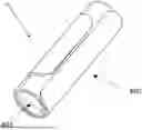
FIG. 12A is a top perspective view of an exemplary embodiment of a training device for stick-based sports of the present disclosure.
FIG. 12B is a rear perspective view of an exemplary embodiment of a training device for stick-based sports of the present disclosure.
FIG. 13 is a front view of an exemplary embodiment of a training device for stick-based sports of the present disclosure.
FIG. 14 is a top view of an exemplary embodiment of a training device for stick-based sports of the present disclosure.
FIG. 15 is a bottom view of an exemplary embodiment of a training device for stick-based sports of the present disclosure.
FIG. 16 is a side view of an exemplary embodiment of a training device for stick-based sports of the present disclosure.
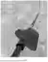
FIG. 17A is a perspective view of an exemplary embodiment of a training device for stick-based sports of the present disclosure in a second position being removably coupled to an apparatus.
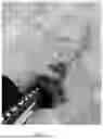
FIG. 17B is a perspective view of an exemplary embodiment of a training device for stick-based sports of the present disclosure removably coupled to an apparatus for use by a user.
FIG. 17C is a top view of an exemplary embodiment of a training device for stick-based sports of the present disclosure removably coupled to an apparatus for use by a user.
FIG. 17D is a side view of an exemplary embodiment of a training device for stick-based sports of the present disclosure removably coupled to an apparatus for use by a user.
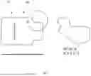
FIG. 18 is a top view of an exemplary embodiment of a training device of the present disclosure before being formed into a generally curvature configuration.
DETAILED DESCRIPTION OF THE INVENTION
The following detailed description includes references to the accompanying drawings, which forms a part of the detailed description. The drawings show, by way of illustration, specific embodiments in which the invention may be practiced. These embodiments, which are also referred to herein as “examples,” are described in enough detail to enable those skilled in the art to practice the invention. The embodiments may be combined, other embodiments may be utilized, or structural, and logical changes may be made without departing from the scope of the present invention. The following detailed description is, therefore, not to be taken in a limiting sense.
Before the present invention of this disclosure is described in such detail, however, it is to be understood that this invention is not limited to particular variations set forth and may, of course, vary. Various changes may be made to the invention described and equivalents may be substituted without departing from the true spirit and scope of the invention. In addition, many modifications may be made to adapt a particular situation, material, composition of matter, process, process act(s) or step(s), to the objective(s), spirit, or scope of the present invention. All such modifications are intended to be within the scope of the disclosure made herein.
Unless otherwise indicated, the words and phrases presented in this document have their ordinary meanings to one of skill in the art. Such ordinary meanings can be obtained by reference to their use in the art and by reference to general and scientific dictionaries.
References in the specification to “one embodiment” indicate that the embodiment described may include a particular feature, structure, or characteristic, but every embodiment may not necessarily include the particular feature, structure, or characteristic. Moreover, such phrases are not necessarily referring to the same embodiment. Further, when a particular feature, structure, or characteristic is described in connection with an embodiment, it is submitted that it is within the knowledge of one skilled in the art to affect such feature, structure, or characteristic in connection with other embodiments whether or not explicitly described.
The following explanations of certain terms are meant to be illustrative rather than exhaustive. These terms have their ordinary meanings given by usage in the art and in addition include the following explanations.
As used herein, the term “and/or” refers to any one of the items, any combination of the items, or all of the items with which this term is associated.
As used herein, the singular forms “a,” “an,” and “the” include plural reference unless the context clearly dictates otherwise.
As used herein, the terms “include,” “for example,” “such as,” and the like are used illustratively and are not intended to limit the present invention.
As used herein, the terms “preferred” and “preferably” refer to embodiments of the invention that may afford certain benefits, under certain circumstances. However, other embodiments may also be preferred, under the same or other circumstances.
Furthermore, the recitation of one or more preferred embodiments does not imply that other embodiments are not useful and is not intended to exclude other embodiments from the scope of the invention.
As used herein, the terms “front,” “back,” “rear,” “upper,” “lower,” “right,” and “left” in this description are merely used to identify the various elements as they are oriented in the FIGS., with “front,” “back,” and “rear” being relative to the apparatus. These terms are not meant to limit the elements that they describe, as the various elements may be oriented differently in various applications.
As used herein, the term “coupled” means the joining of two members directly or indirectly to one another. Such joining may be stationary in nature or movable in nature. Such joining may be achieved with the two members, or the two members and any additional intermediate members being integrally formed as a single unitary body with one another or with the two members or the two members and any additional intermediate members being attached to one another. Such joining may be permanent in nature or alternatively may be removable or releasable in nature. Similarly, coupled can refer to a two member or elements being in communicatively coupled, wherein the two elements may be electronically, through various means, such as a metallic wire, wireless network, optical fiber, or other medium and methods.
It will be understood that, although the terms first, second, etc. may be used herein to describe various elements, these elements should not be limited by these terms. These terms are only used to distinguish one element from another. For example, a first element could be termed a second element, and, similarly, a second element could be termed a first element without departing from the teachings of the disclosure.
Following are more detailed descriptions of various related concepts related to, and embodiments of, methods and apparatus according to the present disclosure. It should be appreciated that various aspects of the subject matter introduced above and discussed in greater detail below may be implemented in any of numerous ways, as the subject matter is not limited to any particular manner of implementation. Examples of specific implementations and applications are provided primarily for illustrative purposes.
Referring now to the figures, FIG. 1 to FIG. 11 of a training device for stick-based sports and capable of selective receipt around a shaft of a stick utilized in these stick-based sports and generally referred to herein as device 10. Most generally the device 10 is configured to have recovery properties, wherein the device 10 is selectively operable between a loosened position 100 to enable rotation of the stick and a fixed position 200 wherein the device 10 is compressed to prevent rotation of the stick during use. The movement of the device 10 between the loosened position 100 and fixed/compressed position 200 is configured to simulate and aid in an understanding of the grip pressure of at least one hand needed to execute certain movements and uses of the stick during these sporting activities. The device 10 is configured to be movable from a first position indicated as the loosened position 100 to a second position indicated as the fixed position 200 when a squeezing force is applied onto the device 10, wherein the device 10 shape generally compresses within the hand and around the shaft. The device 10 is configured to return from the second position 200 to the first position 100 when the application of force (i.e., grip pressure) onto the device 10 is relaxed. Preferably, the device 10 is comprised of a resilient or flexible material that has properties rendering it flexible, thin, compressible, and capable of being coiled.
Accordingly, the device 10 resilient and flexible material 20 is selected to have recovery properties, wherein the flexible material 20 is capable of being movable from the first position 100 to the second position 200 when force is applied onto the flexible material while it is placed onto the stick during use. The flexible material 20 resilient properties enable the device 10 to be capable of recovering from the second position 200 to the first position 100 on its own after the application of force to the flexible material of the device 10 is relaxed. Preferably, the flexible material 20 is thin, compressible, and capable of being coiled. The flexible material 20 can be any material having a durometer as measured on the Shore A hardness scale between 50 and 90 (Shore A 50-90) that renders the material capable of being coiled. The flexible material 20 preferred thickness has a maximum dimension of 0.125 inch (0.125″) with the preferred thickness being 0.06 inch (0.06″) thick with a hardness of 90 on the Shore A scale.
The flexible material 20 of the device 10 can be any resilient material capable of recovery, including, but not limited to, rubber, silicone, thermoplastic elastomers (TPE), or leather. The flexible material 20 can be selected based upon a particular sport or strength level of the user, such as providing one type of material for adult use and another type of material for use by youths. In a preferred embodiment of the present disclosure, the flexible material 20 of the device 10 is provided in a sided assembly wherein a side of the device generally contacting the stick includes a coating 320 in the form of a material to reduce friction during use. Preferably, this coating is a polymer coating such as, but not limited to, a polytetrafluoroethylene (“PTFE”) type or nano-ceramic coating to create a strong high-release and non-stick surface. Although this type of coating is preferred, other similar slick coatings or materials may be used, such as, but not limited to talc, corn starch, PTFE derivatives, nano surface treatments, or other similar materials and coatings to reduce a coefficient of friction of at least one side of the device 10.
The device 10 is generally movable between a flattened and planar surface 300 (FIG. 5, FIG. 6 and FIG. 7) and wrapped state (100, 200) when in use. Accordingly, the device 10 is generally provided in the flattened and planar surface 300, then the device 10 is affixed to a given stick when desired for use by wrapping the device 10 around a shaft of the stick in a cylindrical shape 400 and securing the device 10 upon itself in a desired position (100, 200) through a fastening mechanism 500. The cylindrical shape 400 has an adjustable internal diameter 401 to accommodate a desired diameter of the shaft of the stick the device 10 is utilized upon.
The device 10 method of use generally comprises the device 10 being applied to the shaft in a loosened position 100 (FIG. 8). The loosened position 100 allows for drills requiring axial rotation of the stick where the device 10 is loosely gripped by a user and when desired the device 10 can be compressed against itself and the shaft of the stick to the compressed/fixed position 200 to prevent axial rotation of the stick for drills (FIG. 9), such as shooting and passing, when rotation of the stick is not desired. The flexible material 20 allows for the device 10 to be compressed from the loosened position 100 to the fixed/compressed position 200 (FIG. 8 to FIG. 9), and to return to the loosened position 100 when the application of force is relaxed.
In a top view of the device 10 the features and shape of the stick handling training device can better be seen and described. The device 10 is generally constructed from the flattened and planar surface 300 comprised of the flexible material 20. The device 10 can have a first end 101 opposite a second end 102, with the distance between the first end 101 and the second end 102 defining a length of the device 10. The first end 101 generally forming a tab 110 with a plurality of notched grooves 111. The tab 110 and notched grooves 111 are configured with a size and shape to both conform for receipt within a slot 103 and retain the tab 110 within the slot 103 when desired. The tab 110, notched grooves 111, and slot 103 selected and positioned to accommodate a variety of diameters of shaft sizes of sticks the device 10 is wrapped around.
The slot 103 extends through an entirety of the material and is generally positioned between the first end 101 and the second end 102. As the position of the slot 103 distance from the first end 101 and tab 110 will determine the internal diameter 401 of the cylindrical shape 400 when device 10 is wrapped, the slot 103 can be positioned at a preselected distance to accommodate a desired diameter of the shaft of the stick the device 10 is utilized upon.
As it will be appreciated, the device 10 is provided in a flexible assembly that is configured for universal use on several diameters and types of sticks. The flexible assembly configured for wrapping around the shaft of a stick for aiding in the simulation of a loose hand during stick handling activities.
In use, the device 10 is wrapped into a cylindrical shape 400 via a fastening mechanism 500. The cylindrical shape 400 having the adjustable internal diameter 401 that allows the device 10 to be utilized in several stick sizes. In the preferred embodiment, the tab 110 is inserted into the slot 103 and the plurality of notched grooves 111 retain the device 10 in the cylindrical shape 400. This allows the device 10 to be installed around a stick regardless of knob or grip configuration and does not require a user of the device 10 to axially install from one end of the stick. The flexible material 20 of the device 10 and the selected and preferred material hardness properties render the device 10 capable of being coiled to form a cylinder within which the stick can axially move freely when not gripped by the user.
Alternatively, other types of fastening mechanisms 500, such as a hook and loop, could be utilized to secure the closure. It is envisioned that a removable fastener could be utilized. Referring now to FIG. 10-11, one alternate fastening mechanism 500 is illustrated, with the flattened planar surface 300 having a first side 301 with a first hook or loop portion 501 generally positioned adjacent to the slot 103 between the slot 103 and the tab 110. A second hook or loop portion 502 is positioned on a second side 302 of the planar surface 300 opposing the first side 301 on the tab 110 generally adjacent to the first end 101. Accordingly, when the device 10 is coiled the first hook and loop portion 501 and the second hook and loop portion 502 are configured to be placed into an adjacent and secured position after the tab 110 is received in the slot 103. This assembly provides a secondary and alternate fastening means and ensures that the device 10 is secured in the coiled position 400.
The second side 302, shown in FIG. 11, may include the coating 320 to reduce friction in the coiled position, wherein the sided and coated assembly of the device 10 ensures ease of use of the device 10. Preferably, this coating 320 is a polymer coating of the nano-ceramic or polytetrafluoroethylene (“PTFE”) type, although other similar slick coatings or materials may be used. Accordingly, the device 10 assembly ensures that the second side 302 will be more slippery or generally have a coefficient of friction that will be less than a coefficient of friction of the first side 301.
Additionally, a powder substance, such as, but not limited to, talc, may be used on the inside of the cylinder when wrapped to combat the tackiness.
The device 10 material properties provide that it is collapsible (FIG. 9) such that training progressions can go from stickhandling and free movement axially, to the trainee applying pressure to the device 10 to secure the device 10 upon the stick to enable a user a firm grip to pass and or shoot. Upon relaxing the players grip, the device 10 returns to its cylindrical shape 400 and more progressions/repetitions of stickhandling can be done easily.
Referring now to FIG. 12 to FIGS. 17, an exemplary embodiment of a training device 10 for stick-based sports is illustrated and capable of selective receipt around a shaft of a stick 1000 utilized in these stick-based sports and generally referred to herein as device 10. In some exemplary embodiments, the device 10 can be constructed of a plastic or polymer material that can be generally rigid. The material can have some minimal flex to allow for the device to be removably coupled to a stick or other apparatus, including but not limited to a hockey stick, lacrosse stick or other stick-based device. In some exemplary embodiments, the device can be formed from a one or more pieces of material and formed into a generally tubular shape. The rigid design can have a light flex in some embodiments.
In some exemplary embodiments, a device 10 of the present disclosure can generally be constructed a singular piece of material and formed or pre-formed into a generally curved configuration as shown in FIG. 12. The curved configuration can be semi-cylindrical tube as shown in the FIGS. 12-16. The device 10 can have an exterior surface 210 and an interior surface 211. The device 10 can have a first end 201 opposite a second end 202, with the distance between the first end 201 and the second end 202 defining a length of the device 10. At each end of the first end 201 and second end 202, the device can optionally have a flared portion 204. The flared portion 204 can help maintain a user's grip onto the device 10 and prevent it from slipping off while in use. The flared portions 204a,b can generally extend up from the exterior surface of the body portion 207 of the device 10 at a predetermined angle or radius along at least a portion of the perimeter edge of the first or second ends 201, 202. The flared positions can provide aid in gripping the device by supplying a rest or retention to the end of a user's hand. Additionally, the flared portion can ensure that the end does not inadvertently dig into the surface of the apparatus 1000 thereby allowing it to move up and down the apparatus 1000 freely. The device 10 can have a first edge 205 and a second edge 206 that can be located proximate to each other when the planar piece is formed into a generally curved configuration as shown in FIG. 12A-B. A slot or channel 212 can be formed between the first edge 205 and second edge 206 of the device. The slot 212 can be formed to allow for a stick portion of an apparatus 1000 to be inserted into an interior cavity area 250 of the device 10. The slot 212 can have any suitable shape.
In one exemplary embodiment, the slot 212 can be flared at each end having a first distance between the first edge 205 and the second edge 206. The edges can gradually move closer together and then further apart near the center of the device 10 between the first end 205 and the second end 206. In general, the slot 212 can be formed in any suitable configuration to allow a user to insert an apparatus 1000. The first edge 205 can be located on first plane A-A and the second edge can be located on a second plane B-B. The first and second plane can be different from one another as shown in FIG. 16. In some exemplary embodiments a portion of the first edge 205 can overlap under a portion of the second edge 206. The slot can be any suitable width to allow a desired apparatus 1000 to be positioned within the interior cavity 250 of the device 10.
The curvature and slot 212 can allow for the device 10 to be placed onto an apparatus 1000 by inserting the stick or handle of the apparatus 1000 a slot opening on the edge and the device 10 can be rotated around an axis formed by the handle of the apparatus to place the device 10 onto the apparatus. This can allow the device 10 to be placed onto a handle that may have a ball or larger end greater than the interior diameter of the device at one end. The slot 212 configuration can accommodate a variety of diameters of shaft sizes of apparatus for the device to be placed upon. In some exemplary embodiments, the device 10 can be comprised of a material that can have a slight flex to allow the slot to separate from a first position to a second position to further allow for various sized shaft sizes. In some exemplary embodiments, the flex between the edges can be about In these embodiments, the distance between the first edge 205 and the second edge 206 can be moved from a first position to a second position when inserting the handle or apparatus into the interior cavity 250 of the device 10. The distance between the first edge 205 and second edge 206 can be greater in the second position than the first position. This allows the device 10 to be installed around a stick regardless of knob or grip configuration and does not require a user of the device 10 to axially install from one end of the stick or apparatus 1000. The first edge 205 can have a cut out or flat portion.
The exterior side 210 of the device can similarly have a coating that provides better grip to the user of the device. In some exemplary embodiments, the exterior surface can be embossed, have ridges, or other pattern to provide a user a better grip. The interior surface 211 can be smooth or have a surface coating to ensure smooth sliding movement along the apparatus 1000. In some exemplary embodiments, the interior surface may optionally include a coating or layer to reduce friction in the coiled position, wherein the sided and coated assembly of the device 10 ensures ease of use of the device 10. One exemplary coating can be a polymer coating of the nano-ceramic or polytetrafluoroethylene (“PTFE”) type, although other similar slick coatings or materials may be used. Accordingly, the device 10 sided assembly ensures that the interior side 211 can be more slippery or generally have a coefficient of friction that will be less than a coefficient of friction of the first surface 210. The first surface 210 can have a higher coefficient of friction and its own coating or friction/wear layer to provide greater grip to a user.
The first edge 205 and second edge 206 can overlap a predetermined distance past each other along a horizontal plane as shown in FIGS. 14 and 16. This can help maintain the device 10 on the apparatus 1000 during operation. The amount of overlap can further be increased or decreased based upon the pressure applied to the exterior surface 210 of the device 10 by a user. Similarly, the overlap can be increased or decreased when coupling or decoupling the device 10 from an apparatus 1000. Additionally, a compressive force by a user can change the volume of the interior cavity 250 as well as the distance between the first edge 205 and second edge 206. In some exemplary embodiments, the device can be made of a more rigid material with little to no movement upon compression.
FIGS. 17A-D illustrate an exemplary embodiment of the device of the present disclosure positioned onto a hockey stick. The slot 212 can allow for the device to be placed on to the stick while still maintaining a desired rigidity when in use. The device can be removably coupled to an apparatus by positioning the apparatus between the slot 212 of the device 10. In embodiments having a flexible composition, the distance between the first edge 205 and the second edge 206 can be moved between a first position and a second position. As the device is applied, the distance can increase to allow for various widths or diameters of apparatuses 1000 to be inserted into the interior cavity 250 of the device 10. FIG. 17A illustrates the increased distance between the first edge 205 and the second edge 206 as the device 10 being coupled to the apparatus 1000. FIG. 17B illustrates the decrease in distance between the two edges after the device 10 has been coupled to the apparatus 1000. Similarly, in some exemplary embodiments utilizing a dual plane configuration, the different plane between the first edge 205 and the second edge 206 can allow for the device to be installed with greater ease. In applications of hockey sticks, the slot 212 can be large enough in width to slide on at the stick blade. Additionally, in embodiments that have an overlap between the first edge 205 and second edge 206 can provide greater sliding of the device 10 along the apparatus 1000 without the risk of the apparatus coming decoupled from the apparatus 1000 unintentionally. The interior cavity 250 can be greater in size than the outer dimensions of the apparatus which it is placed on.
FIG. 17C illustrates a user gripping the exterior surface 210 of the device while coupled to an apparatus 1000. The origination and curvature of the second edge 206 can generally approximate a user's thumb and portion of the hand while the first edge can generally approximate the ends of one or more fingers that wrap around the exterior surface 210 of the device 10. The device can be ambidextrous utilized as it can be removed and flipped to allow for ambidextrous training or for multiple users that may have varying dexterity.
In some exemplary embodiments, the interior cavity 250 can have an oblong or non-circular configuration. In some exemplary embodiments, shape of the second edge 206 and/or slot 212 can generally correspond to the shape of a user's hand to provide a comfortable position for the user's thumb and fingers when in use. In embodiments utilizing a flexible material, a user can grip the exterior surface 210 and compress the device 10 to further reduce the size of the interior cavity 250. FIG. 17D illustrates an exemplary embodiment, of the interior cavity 250 shape of the device and the position of the device along an axis of the apparatus 1000. A user can utilize the device 10 to slide their hand up and down the axis of the apparatus 1000 without impediment or undesired rotational force being applied the hand gripping the device 10. The device 10 can aid in increase stick handling and improve technique for the other hand not gripping the device 10. This can allow for a user to more easily move their hand gripping the device 10 up and down the apparatus for training purposes.
In some exemplary embodiments, the device 10 of the present disclosure can be stamped out in a flat shape as shown in FIG. 18. The flat material can then be molded into a desired generally curvature configuration as shown in FIGS. 12-18. The device can have two sides 201,202 that are generally parallel to each other. The first edge 205 and second edge 206 can be cut or formed into a shape that corresponds to the portions of a user's hand. As shown in FIG. 18, some exemplary embodiments can have a first edge 205 configuration that can generally have an flat portion 220 in the center with two angular portions 221a,b that extend out to the respective sides 201,202. The flat portion 220 can generally be perpendicular in orientation to the first side 201 and second side 202. The second edge 206 can have a configuration of generally two angular portions 223a,b extending and generally identical angles from the sides towards a central point 224. The points of intersection can be sharp edges or have a general radius as shown in FIG. 18.
While the invention has been described above in terms of specific embodiments, it is to be understood that the invention is not limited to these disclosed embodiments. Upon reading the teachings of this disclosure many modifications and other embodiments of the invention will come to mind of those skilled in the art to which this invention pertains, and which are intended to be and are covered by both this disclosure and the appended claims. It is indeed intended that the scope of the invention should be determined by proper interpretation and construction of the appended claims and their legal equivalents, as understood by those of skill in the art relying upon the disclosure in this specification and the attached drawings.
Claims
What is claimed is:1. A training device for stick based sports comprising:
a generally cylindrical body having an exterior surface and an interior surface with a cavity formed within, wherein the body has a first end and a second end to form a length of the device,
wherein the device further includes a first edge and a second edge, wherein the first edge and second edge are configured to wrap around a stick and are positioned proximate to each other;
wherein a slot is formed between the first edge and second edge of the body.
2. The device of claim 1, wherein a portion of the first edge is positioned on a first plane and portion of the second edge is positioned on the second plane.
3. The device of claim 2, wherein a portion of the first edge extends past a portion of the second edge.
4. The device of claim 3, wherein the first end includes a first flared portion.
5. The device of claim 4, wherein the second end includes a second flared portion.
6. The device of claim 5, wherein the first flared portion and second flared portions are configured to maintain the interface between the user as well as prevent the ends from catching on the stick while in use.
7. The device of claim 6, wherein the interior surface has a first coefficient of friction and the exterior surface has a second coefficient of friction.
8. The device as in claim 7, being comprised of a material selected from the group consisting of rubber, silicone, thermoplastic elastomers (TPE), and leather.
9. The device of claim 7, being comprised of a polymer.
10. The device of claim 9, wherein the polymer has a predetermined rigidity.
11. The device of claim 10, wherein the distance between the first edge and second edge can be changed by applying a predetermined compressive force.
12. The device of claim 11, wherein the first edge configuration approximates the shape of a user's four fingers that wrap around the exterior surface of the body.
13. The device of claim 12, wherein the second edge configuration approximates the shape of a user's thumb.
14. A method to enable training of stick-based sports using a device as in claim 1, the method comprising the steps of:
providing the a stick handling device, wherein the device includes generally cylindrical body having an exterior surface and an interior surface with a cavity formed within, wherein the body has a first end and a second end to form a length of the device,
wherein the device further includes a first edge and a second edge, wherein the first edge and second edge are configured to wrap around a stick and are positioned proximate to each other;
wherein a slot is formed between the first edge and second edge of the body;
placing the device around a shaft of the stick by wrapping the inserting the stick through the slot of the device;
wherein the device forms a cylindrical shape around the shaft of the stick via the first edge and second edge of the device, the cylindrical shape comprising an adjustable internal diameter based upon the force applied by a user; and
gripping the device loosely during stick handling drills to allow axial rotation of the stick.
15. A method as in claim 14, wherein the device further includes a flair portion at the first end and the second end.
Images & Drawings included:


Sources:
- United States Patent and Trademark Office - verify current appl. status at the USPTO↗
Similar patent applications:
- » 20220347538
TRAINING DEVICE FOR STICK-BASED SPORTS
Recent applications in this class:
- » 20250229150 2025-07-17
CONNECTED HOCKEY TRAINING SYSTEMS AND METHODS - » 20250213949 2025-07-03
HOCKEY STICK GRIP ASSEMBLY - » 20250205574 2025-06-26
INTERACTIVE GAME VIRTUALIZATION AND PRACTICING SYSTEM, AND GAME PRACTICING METHOD USING THE SAME. - » 20250001272 2025-01-02
METHOD AND DEVICE FOR HOCKEY PUCK FACE-OFF TRAINING - » 20240316430 2024-09-26
Ice Hockey Defensive Trainer - » 20240261653 2024-08-08
SINGLE PUCK DRIBBLING PLATE AND MODULAR PUCK DRIBBLING PLATE - » 20240091616 2024-03-21
DEVICE FOR SPORTS TRAINING - » 20240058675 2024-02-22
Positive electrode active material for non-aqueous electrolyte secondary cell, and non-aqueous electrolyte secondary cell - » 20230372804 2023-11-23
Interactive Sports Training System - » 20230249044 2023-08-10
FACE-OFF TRAINING DEVICE AND METHOD OF USE