CLOTHING TREATMENT SYSTEM
US20250257519A1
2025-08-14
19/196,384
2025-05-01
Smart Summary: A clothing treatment system has two main parts: a first apparatus and a second one attached to it. The second part includes a housing that holds a rotating drum and a heat exchanger. There are two openings on the front of the housing; one connects to the drum, and the other allows access to the heat exchanger. A cover door, which can rotate up and down, opens and closes the second opening for easy access. This design helps improve how clothes are treated during washing or drying. 🚀 TL;DR
Abstract:
This clothing treatment system comprises a first clothing treatment apparatus and a second clothing treatment apparatus provided on the first clothing treatment apparatus. The second clothing treatment system comprises: a housing; a drum to be provided in the housing to be rotatable; a heat exchanger to be provided in the housing; a first opening to be provided in the front surface of the housing to be connected to the drum; a second opening to be provided in the front surface of the housing so as to access the heat exchanger; and a cover door which includes a rotating shaft extending along the vertical direction of the clothing treatment system. The cover door opens/closes the second opening that is provided on the front surface of the housing by rotating about the rotating shaft.
Inventors:
- MinJung KIM 44 🇰🇷 Suwon-si, South Korea
- Hyeonuk NA 7 🇰🇷 Suwon-si, South Korea
- Naeyoung PARK 6 🇰🇷 Suwon-si, South Korea
Assignee:
- SAMSUNG ELECTRONICS CO., LTD. 87,924 🇰🇷 Suwon-si, South Korea
Applicant:
Interested in similar patents?
Get notified when new applications in this technology area are published.
Classification:
D06F58/26 » CPC main
Domestic laundry dryers; General details of domestic laundry dryers Heating arrangements, e.g. gas heating equipment
D06F58/08 » CPC further
Domestic laundry dryers having dryer drums rotating about a horizontal axis; Details Driving arrangements
D06F58/206 » CPC further
Domestic laundry dryers; General details of domestic laundry dryers Heat pump arrangements
D06F58/34 » CPC further
Domestic laundry dryers; Control of operations performed in domestic laundry dryers characterised by the purpose or target of the control
D06F58/20 IPC
Domestic laundry dryers General details of domestic laundry dryers
Description
CROSS-REFERENCE TO RELATED APPLICATION
This application is a continuation application is a continuation application, under 35 U.S.C. § 111 (a), of international application No. PCT/KR2023/018367, filed Nov. 15, 2023, which claims priority under 35 U. S. C. § 119 to Korean Patent Application No. 10-2022-0157697, filed Nov. 22, 2022, and Korean Patent Application No. 10-2023-0017359, filed Feb. 9, 2023, the disclosures of which are incorporated herein by reference in their entireties.
TECHNICAL FIELD
The present disclosure relates to a clothing treatment system including at least one clothing treatment apparatus.
BACKGROUND ART
A clothing treatment apparatus is an apparatus for treating and/or managing clothes. The clothing treatment apparatus may include a washing machine and a dryer.
A washing machine is an apparatus that performs washing through friction between laundry, water, and detergent put into a tub by stirring the laundry, water, and detergent together using a driving force of a driving motor. A procedure to be performed by the washing machine may include a washing process of supplying detergent and water to the tub accommodating laundry and washing the laundry while rotating a drum, a rinsing process of supplying water to the tub and rotating the drum to rinse the laundry, and a dewatering process of discharging the water from the tub and rotating the drum to remove moisture from the laundry, regardless of the type of washing machine.
A dryer is an apparatus that dries an object with high-temperature dry air. The dryer dries an object by allowing hot air to pass through a drum while rotating the drum in which the object is accommodated at low speed. A procedure to be performed by the dryer may include a drying process of drying an object.
For convenience of use, a plurality of clothing treatment apparatuses may be connected and used.
DISCLOSURE
Technical Problem
One aspect of the present disclosure provides a clothing treatment system including a first clothing treatment apparatus and/or a second clothing treatment apparatus including a cover door that is provided to be rotatable 180 degrees or more around a rotating shaft extending in a vertical direction.
One aspect of the present disclosure provides a clothing treatment system that allows a cover door of a second clothing treatment apparatus arranged above a first clothing treatment apparatus to be laterally opened and thus prevents structural interference with the first clothing treatment apparatus in response to opening of the cover door.
One aspect of the present disclosure provides a clothing treatment system capable of facilitating withdrawal and insertion of a filter device or a dehumidifying device.
The technical objectives of the disclosure are not limited to the above, and other objectives that are not described above will be clearly understood by those skilled in the art from the above detailed description.
Technical Solution
A clothing treatment system according to the disclosure includes a first clothing treatment apparatus and a second clothing treatment apparatus provided on an upper side of the first clothing treatment apparatus. The second clothing treatment apparatus includes: a housing, a drum rotatable while inside the housing, a heat exchanger provided inside the housing, a first opening provided on a front surface of the housing to be connected to the drum, a second opening provided on the front surface of the housing to allow access to the heat exchanger, and a cover door including a rotating shaft extending along a vertical direction of the clothing treatment system, and configured to open and close the second opening that is provided on the front surface of the housing by rotating around the rotating shaft.
DESCRIPTION OF DRAWINGS
FIG. 1 illustrates a clothing treatment system according to an embodiment.
FIG. 2 illustrates a first clothing treatment apparatus of the clothing treatment system according to an embodiment.
FIG. 3 illustrates a cross-sectional view of the first clothing treatment apparatus of the clothing treatment system according to an embodiment.
FIG. 4 illustrates a second clothing treatment apparatus of the clothing treatment system according to an embodiment.
FIG. 5 illustrates a cross-sectional view of the second clothing treatment apparatus, on which a filter device is mounted, in the clothing treatment system according to an embodiment.
FIG. 6 is a control block diagram of the first clothing treatment apparatus according to an embodiment.
FIG. 7 is a control block diagram of the second clothing treatment apparatus according to an embodiment.
FIG. 8 is a control block diagram of the clothing treatment system according to an embodiment.
FIG. 9 illustrates the second clothing treatment apparatus, on which the filter device is mounted, with a cover door open, in the clothing treatment system according to an embodiment.
FIG. 10 illustrates the filter device of the second clothing treatment apparatus of the clothing treatment system according to an embodiment.
FIG. 11 illustrates the second clothing treatment apparatus, on which a dehumidifying device is mounted, with the cover door open, in the clothing treatment system according to an embodiment.
FIG. 12 illustrates a cross-section of the second clothing treatment apparatus, on which the dehumidifying device is mounted, in the clothing treatment system according to an embodiment.
FIG. 13 illustrates a base of the second clothing treatment apparatus in the clothing treatment system according to an embodiment.
FIG. 14 illustrates a state in which the cover door covers a device accommodating part of the second clothing treatment apparatus in the clothing treatment system according to an embodiment.
FIG. 15 illustrates a state in which the cover door opens to expose the device accommodating part of the second clothing treatment apparatus in the clothing treatment system according to an embodiment.
FIG. 16 illustrates a state in which the cover door and the device accommodating part of the second clothing treatment apparatus are dissembled in the clothing treatment system according to an embodiment.
FIG. 17 is a plan view of a state in which the cover door covers the device accommodating part of the second clothing treatment apparatus in the clothing treatment system according to an embodiment.
FIG. 18 is a plan view of a state in which the cover door is rotated 90 degrees with respect to the device accommodating portion of the second clothing treatment apparatus in the clothing treatment system according to an embodiment.
FIG. 19 is a plan view of a state in which the cover door is rotated 180 degrees with respect to the device accommodating portion of the second clothing treatment apparatus in the clothing treatment system according to an embodiment.
FIG. 20 illustrates a rear view of the cover door and the device accommodating part of the second clothes apparatus and a portion of the housing in the clothing treatment system according to an embodiment.
FIG. 21 illustrates an enlarged view of portion A of FIG. 20.
FIG. 22 illustrates a rear view of the cover door and the device accommodating part of the second clothes apparatus and a portion of the housing in the clothing treatment system according to an embodiment.
FIG. 23 illustrates an enlarged view of portion B of FIG. 22.
FIG. 24 illustrates a state in which a cover door covers a device accommodating part of a second clothing treatment apparatus in a clothing treatment system according to an embodiment.
FIG. 25 illustrates a state in which the cover door opens to expose the device accommodating part of the second clothing treatment apparatus in the clothing treatment system according to an embodiment.
FIG. 26 illustrates an enlarged view of a portion of FIG. 24 viewed at a different angle.
FIG. 27 illustrates an enlarged view of a portion of FIG. 25 viewed at a different angle.
MODES OF THE INVENTION
Various embodiments and terms in this document are not intended to limit the technical features described in this document to specific embodiments, and should be understood to include various modifications, equivalents, or substitutes of the embodiments.
In connection with the description of the drawings, like reference numbers may be used for like or related elements.
The singular form of a noun corresponding to an item may include one item or a plurality of items, unless the relevant context clearly dictates otherwise.
In this document, each of phrases such as “A or B,” “at least one of A and B,” “at least one of A or B,” “A, B or C,” “at least one of A, B and C,” and “at least one of A, B, or C” may include any one of the items listed together in the corresponding one of the phrases, or all possible combinations thereof.
The term “and/or” includes any combination of a plurality of related components or any one of a plurality of related components.
Terms such as “first,” “second,” “primary,” and “secondary” may simply be used to distinguish a given component from other corresponding components, and do not limit the corresponding components in any other respect (e.g., importance or order).
When any (e.g., first) component is referred to as being “coupled” or “connected” to another (e.g., second) component with or without the terms “functionally” or “communicatively”, this means that the any component may be connected to the other component directly (e.g., by a wire), wirelessly, or through a third component.
The terms “comprises” and “has” are intended to indicate that there are features, numbers, steps, operations, components, parts, or combinations thereof described in this document, and do not exclude the presence or addition of one or more other features, numbers, steps, operations, components, parts, or combinations thereof.
When any component is referred to as being “connected”, “coupled”, “supported” or “in contact” with another component, this includes a case in which the components are indirectly connected, coupled, supported, or in contact with each other through a third component as well as directly connected, coupled, supported, or in contact with each other.
When any component is referred to as being located “on” or “over” another component, this includes not only a case in which any component is in contact with another component but also a case in which another component is present between the two components.
A washing machine according to various embodiments may perform washing, rinsing, dewatering, and drying processes. A washing machine is an example of a clothing treatment apparatus, and the clothing treatment apparatus is a concept encompassing an apparatus for washing clothes (objects to be washed, objects to be dried), an apparatus for drying clothes, and an apparatus capable of washing and drying clothes.
A washing machine according to various embodiments may include a top-loading washing machine in which a laundry inlet for putting in or taking out laundry is provided to face upward or a front-loading washing machine in which a laundry inlet is provided to face forward. A washing machine according to various embodiments may include a washing machine of another loading method other than a top-loading washing machine and a front-loading washing machine.
In the case of a top-loading washing machine, laundry may be washed using a water current occurred by a rotating body such as a pulsator. In the case of a front-loading washing machine, laundry may be washed by rotating a drum to repeatedly raise and drop laundry. The front-loading washing machine may include a drying coupled washing machine capable of drying laundry accommodated inside a drum. The drying coupled washing machine may include a hot air supply device for supplying high-temperature air into the drum and a condensing device for removing moisture from air discharged from the drum. For example, the drying coupled washing machine may include a heat pump device. A washing machine according to various embodiments may include a washing machine using a washing method other than the above-described washing method.
Hereinafter, a clothing treatment system according to various embodiments will be described in detail with reference to the accompanying drawings.
FIG. 1 illustrates a clothing treatment system according to an embodiment. FIG. 2 illustrates a first clothing treatment apparatus of the clothing treatment system according to an embodiment. FIG. 3 illustrates a cross-sectional view of the first clothing treatment apparatus of the clothing treatment system according to an embodiment. FIG. 4 illustrates a second clothing treatment apparatus of the clothing treatment system according to an embodiment. FIG. 5 illustrates a cross-sectional view of the second clothing treatment apparatus of the clothing treatment system according to an embodiment.
As illustrated in FIG. 1, a clothing treatment system 1 may include a first clothing treatment apparatus 10 and a second clothing treatment apparatus 60 mounted on the first clothing treatment apparatus 10. The second clothing treatment apparatus 60 may be provided on one side of the first clothing treatment apparatus 10. For example, the second clothing treatment apparatus 60 may be mounted at an upper end of the first clothing treatment apparatus 10.
The first clothing treatment apparatus 10 may be a washing machine or a dryer. For example, the first clothing treatment apparatus 10 may be a washing machine.
Referring to FIGS. 2 and 3, the first clothing treatment apparatus 10 according to various embodiments may include a first housing 11 accommodating various components therein. The first housing 11 may be provided in the form of a box having a laundry inlet 12 formed on one side thereof.
The first clothing treatment apparatus 10 may include a first front frame 11a forming a front surface thereof. The laundry inlet 12 may be formed on the first front frame 11a.
The first clothing treatment apparatus 10 may include a first door 13 provided to open and close the laundry inlet 12. The first door 13 may be rotatably mounted to the first housing 11 by a first hinge 14. At least one portion of the first door 13 may be provided to be transparent or translucent so that the inside of the first housing 11 may be seen.
The first clothing treatment apparatus 10 may include a tub 20 provided inside the first housing 11 to store water. The tub 20 may be provided in a substantially cylindrical shape with a tub opening 22 formed on one side thereof, and disposed inside the first housing 11 such that the tub opening 22 is disposed to correspond to the laundry inlet 12.
The tub 20 may be connected to the first housing 11 by a damper 29. The damper 29 may absorb vibration occurred when a first drum 30 rotates to damp the vibration transferred to the first housing 11.
The first clothing treatment apparatus 10 may include the first drum 30 provided to accommodate laundry.
The first drum 30 may be disposed inside the tub 20 such that a first drum opening 32 provided on one side thereof corresponds to the laundry inlet 12 and the tub opening 22. Laundry may be accommodated in the first drum 30 or taken out of the first drum 30 by sequentially passing through the laundry inlet 12, the tub opening 22, and the first drum opening 32.
The first drum 30 may perform respective operations according to washing, rinsing, and/or dewatering processes while rotating inside the tub 20. A plurality of passing holes 34 is formed on a cylindrical wall of the first drum 30 so that water stored in the tub 20 may flow into the first drum 30 or flow out of the first drum 30. At least one first lifter 35 may be installed on an inner circumferential surface of the first drum 30 so that laundry may be raised and dropped when the first drum 30 rotates.
The first clothing treatment apparatus 10 may include a first driving device 40 configured to rotate the first drum 30. The first driving device 40 may include a first driving motor 41 and a first rotating shaft 42 provided to transmit a driving force generated by the first driving motor 41 to the first drum 30. The first rotating shaft 42 may pass through the tub 20 to be connected to the first drum 30.
The first driving device 40 may perform each operation according to the washing, rinsing, and/or dewatering, or drying process by forward or reversely rotating the first drum 30.
The first clothing treatment apparatus 10 may include a water supply device 50 configured to supply water to the tub 20. The water supply device 50 may include a water supply pipe 51 and a water supply valve 52 provided on the water supply pipe 51. The water supply pipe 51 may be connected to an external water supply source. The water supply pipe 51 may extend from an external water supply source to a detergent supply device 53 and/or the tub 20. Water may be supplied to the tub 20 through the detergent supply device 53. Water may be supplied to the tub 20 without passing through the detergent supply device 53.
The water supply valve 52 may open or close the water supply pipe 51 in response to an electrical signal of a first controller 23 (see FIG. 6). The water supply valve 52 may allow water to be supplied to the tub 20 or block water from being supplied to the tub 20, from the external water supply source. The water supply valve 52 may include, for example, a solenoid valve opening or closing in response to an electrical signal.
The first clothing treatment apparatus 10 may include the detergent supply device 53 configured to supply detergent to the tub 20. The detergent supply device 53 may include a manual detergent supply device requiring a user to put detergent to be used for each washing, and an automatic detergent supply device storing a large amount of detergent and automatically putting a predetermined amount of detergent during washing. The detergent supply device 53 may include a detergent box for storing detergent. The detergent supply device 53 may be configured to supply the detergent into the tub 20 during a water supply process. Water supplied through the water supply pipe 51 may be mixed with the detergent by passing through the detergent supply device 53. Water mixed with detergent may be supplied into the tub 20. The detergent may be used as a term encompassing detergent for pre-washing, detergent for main washing, fabric softener, bleach, and the like, and the detergent box may be divided into a detergent storage area for pre-washing, a detergent storage area for main washing, a fabric softener storage area, and a bleaching agent storage area.
The first clothing treatment apparatus 10 may include a drainage device 54 configured to discharge water accommodated in the tub 20 to the outside. The drainage device 54 may include a drain pipe 55 extending from a bottom of the tub 20 to the outside of the first housing 11, a drain valve 56 provided on the drain pipe 55 to open and close the drain pipe 55, and a pump 57 provided on the drain pipe 55. The pump 57 may pump water in the drain pipe 55 to the outside of the first housing 11.
According to various embodiments, the first clothing treatment apparatus 10 may further include a heater for heating water stored in the tub 20.
According to various embodiments, the first clothing treatment apparatus 10 may further include a heater for heating water that is supplied through the water supply device 50.
The second clothing treatment apparatus 60 may be a washing machine or a dryer. For example, the second clothing treatment apparatus 60 may be a dryer.
Referring to FIGS. 4 and 5, the second clothing treatment apparatus 60 according to various embodiments may include a second housing 61 accommodating various components therein. The second housing 61 may be provided in the form of a box in which an object inlet 62 is formed on one side thereof. In this specification, the object inlet 62 may refer to a first opening 62.
The second clothing treatment apparatus 60 may include a second front frame 61a forming a front surface thereof. The object inlet 62 may be formed on the second front frame 61a.
The second clothing treatment apparatus 60 may include a second door 63 provided to open and close the object inlet 62. The second door 63 may be rotatably mounted to the second housing 61 by a second hinge 64. At least one portion of the second door 63 may be provided to be transparent or translucent so that the inside of the second housing 61 may be seen.
The second clothing treatment apparatus 60 may include a second drum 70 provided to accommodate an object. The second drum 70 may be disposed inside the second housing 61 such that a second drum opening 72 provided on one side thereof corresponds to the object inlet 62. The object may be accommodated in the second drum 70 or taken out of the second drum 70 by sequentially passing through the object inlet 62 and the second drum opening 72. The second drum 70 may be rotatably provided inside the second housing 61.
The second clothing treatment apparatus 60 may include a second driving device 73 configured to rotate the second drum 70. The second driving device 73 may include a second driving motor and a second rotating shaft provided to transmit a driving force generated by the second driving motor to the second drum 70.
The second drum 70 may include an air inlet 71 through which air is introduced into the second drum 70. Air inside the second drum 70 may be discharged to the outside of the second drum 70 through the second drum opening 72. The air inlet 71 may be positioned on a side opposite to one side of the second drum 70 where the second drum opening 72 is positioned. For example, the air inlet 71 may be positioned at the rear of the second drum 70, and the second drum opening 72 may be positioned at the front of the second drum 70.
High-temperature dry air may be introduced into the second drum 70 through the air inlet 71 to dry the object accommodated in the second drum 70. Air containing a large amount of moisture after drying the object may be discharged from the second drum 70 through the second drum opening 72.
At least one second lifter 74 may be provided inside the second drum 70. The second lifter 74 may raise and drop the object so that the object comes into contact with the hot air while floating in an inner space of the second drum 70.
Inside the second housing 61, a heat pump 80 configured to heat and condense air may be provided. An evaporator 81, a condenser 82, a compressor 83, an expansion device, and the like constituting the heat pump 80 may be disposed below the second drum 70. Refrigerant may be circulated through a series of processes leading to compression-condensation-expansion-evaporation. Specifically, the heat pump 80 may include the evaporator 81, the condenser 82, the compressor 83, and the expansion device. The evaporator 81 and the condenser 82 may exchange heat with air.
The compressor 83 compresses and discharges the refrigerant in a high-temperature and high-pressure state, and the discharged refrigerant may be introduced into the condenser 82. The condenser 82 may condense the compressed refrigerant and dissipate heat to the surroundings through the condensation process. The expansion device may expand the high-temperature and high-pressure refrigerant condensed in the condenser 82 to a low-pressure state. The evaporator 81 may evaporate the expanded refrigerant and take heat from the surroundings through the evaporation process.
As an operating RPM of the compressor 83 increases, an amount of heat radiated to the surroundings through the condensation process of the condenser 82 may increase.
When an object is put into the second clothing treatment apparatus 60 and operated in a drying mode, high-temperature and high-humidity air discharged from the second drum 70 may pass through the evaporator 81. Accordingly, the high-temperature and high-humidity air discharged from the second drum 70 may be cooled while passing through the evaporator 81 and thus changed into low-temperature dry air. At this time, condensed water may be generated as the high-temperature and high-humidity air is cooled in the evaporator 81. The condensed water may be moved to a recovery water container or drained to the outside of the second housing 61. Air in a low-temperature dry state after passing through the evaporator 81 may pass through the condenser 82. Accordingly, the low-temperature dry air discharged from the evaporator 81 may be heated while passing through the condenser 82 and thus changed into high-temperature dry air. The high-temperature dry air may be introduced into the second drum 70 through the air inlet 71 to dry the object. As the object is dried, high-temperature and high-humidity air containing a large amount of moisture may be discharged through the second drum opening 72. The discharged air may pass through the evaporator 81 again. In summary, air may dry an object accommodated in the second drum 70 while circulating inside the second housing 61.
In the drying mode, a closed type flow path may be formed inside the second housing 61 of the second clothing treatment apparatus 60. The closed type flow path may be an air movement path (refer to arrows in FIG. 5) formed to circulate air inside the second housing 61 through the heat pump 80 and the second drum 70. The closed type flow path may not communicate with the outside of the second housing 61 so that air outside the second housing 61 does not flow in or out. That is, the flow of air may form a closed loop.
The second clothing treatment apparatus 60 may include a heater 86 provided in the closed type flow path. The heater 86 may be implemented through a heating coil, but is not limited thereto, and may be implemented through various known devices. The heater 86 may further heat the air heated while passing through the condenser 82 or heat the air sucked in from the outside without being heated through the heat pump 80.
Referring to FIGS. 4 and 5, the second clothing treatment apparatus 60 may include a housing opening 69 provided on a front surface of the second housing 61 to allow access to the evaporator 81 of the heat pump 80. A filter device 102 may be mounted inside the second housing 61 through the housing opening 69. Specifically, the filter device 102 may be detachably mounted on a device accommodating part 120 formed inside the second housing 61 through the housing opening 69. When the filter device 102 is mounted on the accommodating part 68, the second clothing treatment apparatus 60 may perform the drying mode (drying operation) for drying objects such as clothes. In addition, a cover door 110 may be provided on the front surface of the second housing 61 to open and close the housing opening 69. In this specification, the housing opening (69) may refer to a second opening (69).
In a state in which the cover door 110 closes the housing opening 69, as a front surface of the cover door 110 and the front surface of the second housing 61 are connected, a surface connected smoothly without a step is formed. When the filter device 102 is not mounted inside the second housing 61, the user may access the evaporator 81 disposed at the front between the heat exchangers 81 and 82 through the housing opening 69. When the dryer is used for a long time, foreign substances such as lint may be attached to the heat exchangers 81 and 82, and the user may remove these foreign substances through the housing opening 69.
The filter device 102 may be detachably mounted on the second clothing treatment apparatus 60. Specifically, the filter device 102 may be detachably mounted inside the second housing 61 through the housing opening 69. The filter device 102 may be mounted on the device accommodating part 120 or may be separate from the device accommodating part 120.
A fan 90 may be disposed below the second drum 70. The fan 90 may circulate air inside the second housing 61. The fan 90 may form a circulating airflow passing through the second drum 70 inside the second housing 61.
The second clothing treatment apparatus 60 may include a fan motor (91 in FIG. 7) configured to rotate the fan 90. The fan 90 may be rotated by a driving force generated from the fan motor 91.
According to various embodiments, the fan motor 91 for rotating the fan 90 and a second drum motor 91, 73a for rotating the second drum 70 may be the same configuration.
In an embodiment, one of the motors 91 and 73a may be connected to rotating shafts different from each other to simultaneously rotate the fan 90 and the second drum 70.
When one of the motors 91 and 73a is connected to rotating shafts different from each other to simultaneously rotate the fan 90 and the second drum 70, a rotational speed of the fan 90 and a rotational speed of the second drum 70 may be different from each other. For example, the rotational speed of the fan 90 may be faster than the rotational speed of the second drum 70.
According to various embodiments, the fan motor for rotating the fan 90 and the second drum motor 73a for rotating the second drum 70 may be provided separately from each other.
A leg 140 may be provided on a lower surface of the second clothing treatment apparatus 60. The leg 140 may be provided on the lower surface of the second clothing treatment apparatus 60 to support the second clothing treatment apparatus 60.
FIG. 6 is a control block diagram of the first clothing treatment apparatus according to an embodiment.
Referring to FIG. 6, in an embodiment, the first clothing treatment apparatus 10 may include a first user interface device 15, the first driving device 40, the water supply device 50, the drainage device 54, a first sensor device 18, first communication circuitry 19, and the first controller 23.
The first user interface device 15 may provide a user interface for interaction between the user and the first clothing treatment apparatus 10.
The first user interface device 15 may include at least one first input interface 16 and at least one first output interface 17.
In an embodiment, the first user interface device 15 may be disposed on one side of the first housing 11, but the position of the first user interface device 15 is not limited thereto.
The at least one first input interface 16 may convert sensory information received from the user into an electrical signal.
The at least one first input interface 16 may include a power button, an operation button, a course selection dial (or course selection button), and washing/rinsing/dewatering setting buttons. The at least one first input interface 16 may include, for example, a tact switch, a push switch, a slide switch, a toggle switch, a micro switch, a touch switch, a touch pad, a touch screen, a jog dial, and/or a microphone, and the like.
The at least one first output interface 17 may transfer various data related to operations of the first clothing treatment apparatus 10 to the user by generating sensory information.
For example, the at least one first output interface 17 may transfer information related to a washing course, an operating time of the first clothing treatment apparatus 10, and washing/rinsing/dewatering settings to the user. Information on the operations of the first clothing treatment apparatus 10 may be output through a screen, indicator, voice, and the like. The at least one first output interface 17 may include, for example, a liquid crystal display (LCD) panel, a light emitting diode (LED) panel, a speaker, and the like.
The washing course may include washing settings (e.g., washing temperature, number of rinsing, dewatering intensity, etc.) preset by a designer of the first clothing treatment apparatus 10 depending on the type (e.g., blanket, underwear, etc.) and material (e.g., wool, etc.) of laundry. For example, standard washing may include washing settings that may be applied to most laundry, and blanket washing may include an optimized washing setting for washing a blanket. The washing course may be classified into, for example, standard washing, strong washing, delicate clothing washing, blanket washing, baby clothing washing, towel washing, small amount washing, boiling washing, power saving washing, outdoor clothing washing, rinsing/dewatering, dewatering, and the like.
According to various embodiments, the washing course may include a plurality of courses tailored to user needs. For example, the washing course may include an energy saving course, a time saving course, a low noise course, and the like.
The energy saving course corresponds to a course for minimizing energy required to perform a washing cycle. When the first clothing treatment apparatus 10 performs the washing cycle corresponding to the energy saving course, an operation of the heater for heating water stored in the tub 20 may be minimized.
The time saving course corresponds to a course for minimizing the time required to perform the washing cycle. When the first clothing treatment apparatus 10 performs the washing cycle corresponding to the time saving course, the number of times of washing process, rinsing process, and/or dewatering process may be minimized, or the time required for washing process, rinsing process, and/or dewatering process may be minimized.
The low noise course corresponds to a course for minimizing noise occurred from the first clothing treatment apparatus 10 while performing the washing cycle. When the first clothing treatment apparatus 10 performs the washing cycle corresponding to the low noise course, a maximum RPM of the first drum 30 may be minimized in the washing process, the rinsing process and/or the dewatering process.
In the present disclosure, courses depending on special needs of the user, such as the energy saving course, the time saving course, and the low noise course, may be defined as specialized courses.
In the present disclosure, the courses other than the specialized courses (e.g., standard courses) may be defined as general courses.
A first memory 25 may store algorithms of a plurality of the washing courses corresponding to the plurality of washing courses. The algorithms of the plurality of washing courses refer to algorithms for controlling a plurality of components (e.g., the first driving device 40, the water supply device 50, the drainage device 54, and/or the heater) in the washing cycle.
A first processor 24 may perform a washing course based on an algorithm of an operation course set based on a user input among the algorithms of the plurality of washing courses stored in the first memory 25.
The first driving device 40 may include the first drum motor 41 for providing a driving force for rotating the first drum 30. The first driving device 40 may operate based on a control signal of the first controller 23.
The water supply device 50 may include the water supply valve 52 provided to open and close the water supply pipe 51 extending from an external water supply source to the detergent supply device 53 and/or the tub 20. The water supply valve 52 may be opened and closed based on a control signal of the first controller 23.
The drainage device 54 may include the drainage pump 57 provided to discharge water from the tub 20 to the outside of the washing machine housing 11. The drainage pump 57 may operate based on a control signal of the first controller 23.
The first sensor device 18 may include at least one sensor provided to obtain information related to an operating state of the first clothing treatment apparatus 10.
For example, the first sensor device 18 may include at least one of a water level sensor provided to detect a water level of the tub 20, a sensor provided to detect an operating state of the first driving device 40, a flow sensor provided to detect a flow rate introduced into the tub 20 through the water supply device 50, and a sensor provided to detect an operating state of the drainage device 54.
According to various embodiments, the first sensor device 18 may include at least one sensor provided to detect a weight of laundry accommodated in the first drum 30.
According to various embodiments, the first sensor device 18 may include a vibration sensor provided to detect a vibration value of the tub 20. The vibration sensor may detect vibration of the tub 20. Specifically, the vibration sensor may detect vibration of the tub 20 occurred by rotation of the first drum 30 during the washing cycle (e.g., the dewatering process). Eccentricity of the first drum 30 may occur due to unbalance of laundry disposed inside the first drum 30, and vibration of the tub 20 may occur due to the eccentricity of the first drum 30. When a rotational speed of the first drum 30 increases in a state in which the laundry is disposed to be unbalanced, the vibration of the tub 20 may increase, and the noise caused by the vibration of the tub 20 may also increase.
According to various embodiments, even when the first clothing treatment apparatus 10 and the second clothing treatment apparatus 60 operate together, the vibration of the tub 20 may increase due to frequency resonance.
The vibration sensor may output a vibration signal related to vibration of the tub 20. An amplitude of the vibration signal may be defined as a vibration value when the tub 20 vibrates.
In an embodiment, the first controller 23 may convert a vibration signal in a time domain output from the vibration sensor into a vibration signal in a frequency domain, and process the vibration signal in the frequency domain. The vibration sensor may include a six-axis sensor capable of detecting displacement in six axes (X, Y, Z, Pitch, Roll, and Yaw).
The sensor provided to detect the operating state of the first driving device 40 may include, for example, a current sensor measuring a driving current applied to the first drum motor 41, but is not limited thereto.
The sensor provided to detect the operating state of the drainage device 54 may include, for example, a current sensor provided to measure a driving current applied to the drainage pump 57, but is not limited thereto.
The first clothing treatment apparatus 10 may include the first communication circuitry 19 for wired and/or wireless communication with external devices (e.g., servers, user devices, and/or other home appliances).
The user devices and/or other home appliances may include various electronic devices such as smartphones, notebooks, laptops, smart watches, IoT hub devices, other home appliances such as a television and/or the second clothing treatment apparatus 60, holder-type tablets, and speakers.
The first communication circuitry 19 may include a short-range communication module and/or a long-range communication module.
The first communication circuitry 19 may transfer data to an external device or receive data from an external device. For example, the first communication circuitry 19 may establish communication with servers, user devices, and/or other home appliances, and transfer/receive various types of data.
To this end, the first communication circuitry 19 may support establishment of a direct (e.g., wired) communication channel or wireless communication channel between external devices, and communication through the established communication channel. According to an embodiment, the first communication circuitry 19 may include a wireless communication module (e.g., a cellular communication module, a short-range wireless communication module, or a global navigation satellite system (GNSS) communication module) or a wired communication module (e.g., a local area network (LAN) communication module, or a power line communication module). A corresponding communication module among these communication modules may communicate with external devices through a first network (e.g., a short-range communication network such as Bluetooth, wireless fidelity (Wi-Fi) direct, and infrared data association (IrDA)) or a second network (e.g., a long-range communication network such as a legacy cellular network, a 5G network, a next-generation telecommunications network, the Internet, and a computer network (e.g. LAN or WAN)). These various types of communication modules may be integrated as one component (e.g., a single chip) or implemented as a plurality of separate components (e.g., a plurality of chips).
The short-range wireless communication modules may include, but are not limited to, a Bluetooth communication module, a Bluetooth low energy (BLE) communication module, a near field communication module, a WLAN (Wi-Fi) communication module, a ZigBee communication module, an infrared data association (IrDA) communication module, a Wi-Fi direct (WFD) communication module, an ultra-wideband (UWB) communication module, an Ant+ communication module, a microwave (uWave) communication module, and the like.
The long-range communication modules may include communication modules that perform various types of long distance communications, and may include mobile communication circuitry. The mobile communication circuitry transfers and receives radio signals with at least one of a base station, an external terminal, and a server on a mobile communication network.
In an embodiment, the first communication circuitry 19 may communicate with an external device such as a server, user device, and other home appliance through a nearby access point (AP). The access point may connect a local area network (LAN) to which the first clothing treatment apparatus 10 and/or a user device and/or other home appliance are connected, to a wide area network (WAN) to which a server is connected. The first clothing treatment apparatus 10 and/or the user device and/or the other home appliance may be connected to the server through the wide area network (WAN).
The first controller 23 may control various components (e.g., the first driving device 40, the water supply device 50, and the drainage device 54) of the first clothing treatment apparatus 10. The first controller 23 may control various components of the first clothing treatment apparatus 10 to perform at least one process including water supply, washing, rinsing, and/or dewatering depending on the user input. For example, the first controller 23 may control the first drum motor 41 of the first driving device 40 to adjust the rotational speed (RPM) of the first drum 30, control the water supply valve 52 of the water supply device 50 to supply water to the tub 20, or control the drainage pump 57 of the drainage device 54 to discharge water in the tub 20 to the outside.
The first controller 23 may include hardware such as a CPU, a microcomputer and a memory, and software such as a control program. For example, the first controller 23 may include algorithms for controlling operations of the components in the first clothing treatment apparatus 10, the at least one first memory 25 for storing data in the form of a program, and the at least one first processor 24 for performing the above-described operations and operations, which will be described later, using data stored in the at least one first memory 25. The first memory 25 and the first processor 24 may be implemented as separate chips. The first processor 24 may include one or more processor chips or may include one or more processing cores. The first memory 25 may include one or more memory chips or may include one or more memory blocks. The first memory 25 and the first processor 24 may be implemented as a single chip.
FIG. 7 is a control block diagram of the second clothing treatment apparatus according to an embodiment.
Referring to FIG. 7, in an embodiment, the second clothing treatment apparatus 60 may include a second user interface device 75, the second driving device 73, the heater 86, and the fan motor 91, the heat pump 80, second communication circuitry 94, a second sensor device 79, and a second controller 97.
The second user interface device 75 may provide a user interface for interaction between the user and the second clothing treatment apparatus 60.
The second user interface device 75 may include at least one second input interface 76 and at least one second output interface 77.
In an embodiment, the second user interface device 75 may be disposed on one side of the second housing 61, but the position of the second user interface device 75 is not limited thereto.
The at least one second input interface 76 may convert sensory information received from the user into an electrical signal.
The at least one second input interface 76 may include a power button, an operation button, a course selection dial (or course selection button), and a drying setting button. The at least one second input interface 76 may include, for example, a tact switch, a push switch, a slide switch, a toggle switch, a micro switch, a touch switch, a touch pad, a touch screen, a jog dial, and/or a microphone, and the like.
The at least one second output interface 77 may transfer various data related to operations of the second clothing treatment apparatus 60 to the user by generating sensory information.
For example, the at least one second output interface 77 may transfer information related to a drying course, an operating time of the second clothing treatment apparatus 60 and a drying setting to the user. Information on the operations of the second clothing treatment apparatus 60 may be output through a screen, indicator, voice, and the like. The at least one second output interface 77 may include, for example, a liquid crystal display (LCD) panel, a light emitting diode (LED) panel, a speaker, and the like.
The drying course may include drying settings (e.g., drying temperature, drying time, drying intensity, etc.) preset by a designer of the second clothing treatment apparatus 60 depending on the type (e.g., blanket, underwear, etc.) and material (e.g., wool, etc.) of an object. For example, standard drying may include drying settings that may be applied to most objects, and blanket drying may include an optimized drying setting for drying a blanket. The drying course may be classified into, for example, standard drying, strong drying, delicate clothing drying, blanket drying, baby clothing drying, towel drying, small amount drying, power saving drying, outdoor clothing drying, and the like.
According to various embodiments, the drying course may include a plurality of courses tailored to user needs. For example, the drying course may include an energy saving course, a time saving course, a low noise course, and the like.
The energy saving course corresponds to a course for minimizing energy required to perform a drying process. When the second clothing treatment apparatus 60 performs the drying process corresponding to the energy saving course, an operation of the heater 86 may be minimized.
The time saving course corresponds to a course for minimizing the time required to perform the drying process. When the second clothing treatment apparatus 60 performs the drying process corresponding to the time saving course, an operating time of the heater 86 and/or an operating frequency of the compressor 83 may increase.
The low noise course corresponds to a course for minimizing noise occurred from the second clothing treatment apparatus 60 while performing the drying process. When the second clothing treatment apparatus 60 performs the drying process corresponding to the low noise course, a maximum RPM of the second drum 70 may be minimized.
In the present disclosure, courses depending on special needs of the user, such as the energy saving course, the time saving course, and the low noise course, may be defined as specialized courses.
In the present disclosure, the courses other than the specialized courses (e.g., standard courses) may be defined as general courses.
A second memory 99 may store algorithms of a plurality of the drying courses corresponding to the plurality of drying courses. The algorithms of the plurality of drying courses refer to algorithms for controlling a plurality of components (e.g., the second driving device 73, the heater 86, the fan motor 91, and/or the compressor 83) in the drying process.
A second processor 98 may perform a drying process based on an algorithm of an operation course set based on the user input among the algorithms of the plurality of drying courses stored in the second memory 99.
The second driving device 73 may include the second drum motor 73a providing a driving force for rotating the second drum 70. The second driving device 73 may operate based on a control signal of the second controller 97.
According to various embodiments, the second controller 97 may control the second driving device 73 based on the algorithm of the operation course selected by the user.
The heater 86 may further heat the air heated while passing through the condenser 82 or heat the air sucked in from the outside without being heated through the heat pump 80.
The heater 86 may operate based on a control signal of the second controller 97.
According to various embodiments, the second controller 97 may control the heater 86 based on the algorithm of the operation course selected by the user.
The fan motor 91 may rotate the fan 90 for circulating air in the second housing 61.
The fan motor 91 may operate based on a control signal of the second controller 97.
According to various embodiments, the second controller 97 may control the fan motor 91 based on the algorithm of the operating course selected by the user.
As described above, the fan motor 91 for rotating the fan 90 and the second drum motor 73a for rotating the second drum 70 may be the same configuration.
In an embodiment, when one of the motors 91 and 73a is connected to rotating shafts different from each other to simultaneously rotate the fan 90 and the second drum 70, the second controller 97 may drive one of the motors 91 and 73a at a target RPM corresponding to a target RPM of the fan 90 or a target RPM of the second drum 70.
According to various embodiments, when the fan motor 91 for rotating the fan 90 and the second drum motor 73a for rotating the second drum 70 are provided separately from each other, the second controller 97 may drive the fan motor 91 based on the target RPM of the fan 90, and drive the second drum motor 73a based on the target RPM of the second drum 70.
The heat pump 80 configured to generate hot air to be supplied to the second drum 70 may include the compressor 83 compressing the refrigerant.
The compressor 83 may operate based on a control signal of the second controller 97.
According to various embodiments, the second controller 97 may control the compressor 83 based on the algorithm of the operation course selected by the user.
The second sensor device 79 may include at least one sensor provided to obtain information related to an operating state of the second clothing treatment apparatus 60.
According to various embodiments, the second sensor device 79 may include at least one sensor provided to detect a weight of an object accommodated in the second drum 70.
According to various embodiments, the second sensor device 79 may include a temperature sensor provided to detect a temperature in the second housing 61 and/or a sensor provided to detect an operating state of the second driving device 73.
The temperature sensor detecting the temperature in the second housing 61 may be provided anywhere inside the second housing 61. According to various embodiments, the temperature sensor may be provided on an outlet side of the condenser 82 or may be provided on a downstream side of the heater 86.
According to various embodiments, the second sensor device 79 may include a vibration sensor provided to detect a vibration value of the second housing 61.
The second clothing treatment apparatus 60 may include the second communication circuitry 94 for wired and/or wireless communication with external devices (e.g., servers, user devices, and/or other home appliances).
The user devices and/or other home appliances may include various electronic devices such as smartphones, notebooks, laptops, smart watches, IoT hub devices, other home appliances such as a television and/or the second clothing treatment apparatus 60, holder-type tablets, and speakers.
The second communication circuitry 94 may include a short-range communication module and/or a long-range communication module.
The second communication circuitry 94 may transfer data to an external device or receive data from an external device. For example, the second communication circuitry 94 may establish communication with servers, user devices, and/or other home appliances, and transfer/receive various types of data.
To this end, the second communication circuitry 94 may support establishment of a direct (e.g., wired) communication channel or wireless communication channel between external devices, and communication through the established communication channel. According to an embodiment, the second communication circuitry 94 may include a wireless communication module (e.g., a cellular communication module, a short-range wireless communication module, or a global navigation satellite system (GNSS) communication module) or a wired communication module (e.g., a local area network (LAN) communication module, or a power line communication module). A corresponding communication module among these communication modules may communicate with external devices through a first network (e.g., a short-range communication network such as Bluetooth, wireless fidelity (Wi-Fi) direct, and infrared data association (IrDA)) or a second network (e.g., a long-range communication network such as a legacy cellular network, a 5G network, a next-generation telecommunications network, the Internet, and a computer network (e.g. LAN or WAN)). These various types of communication modules may be integrated as one component (e.g., a single chip) or implemented as a plurality of separate components (e.g., a plurality of chips).
The short-range wireless communication modules may include, but are not limited to, a Bluetooth communication module, a Bluetooth low energy (BLE) communication module, a near field communication module, a WLAN (Wi-Fi) communication module, a ZigBee communication module, an infrared data association (IrDA) communication module, a Wi-Fi direct (WFD) communication module, an ultra-wideband (UWB) communication module, an Ant+ communication module, a microwave (uWave) communication module, and the like.
The long-range communication modules may include communication modules that perform various types of long distance communications, and may include mobile communication circuitry. The mobile communication circuitry transfers and receives radio signals with at least one of a base station, an external terminal, and a server on a mobile communication network.
In an embodiment, the second communication circuitry 94 may communicate with an external device such as a server, user device, and other home appliance through a nearby access point. The access point may connect a local area network (LAN) to which the second clothing treatment apparatus 60 and/or a user device and/or other home appliance are connected, to a wide area network (WAN) to which a server is connected. The second clothing treatment apparatus 60 and/or the user device and/or the other home appliance may be connected to the server through the wide area network (WAN).
The second controller 97 may control various components (e.g., the second driving device 73, the heater 86, the fan motor 91, and/or the compressor 83) of the second clothing treatment apparatus 60. The second controller 97 may control various components of the second clothing treatment apparatus 60 to perform the drying process depending on the user input. For example, the second controller 97 may control the second drum motor 73a of the second driving device 73 to adjust the rotational speed (RPM) of the second drum 70, control the operation of the heater 86 to quickly heat air in the second drum 70, control an operation of the compressor 83 to generate hot air to be supplied to the second drum 70, or control an operation of the fan motor 91 to circulate hot air generated by the heat pump 80 into the second drum 70.
The second controller 97 may include hardware such as a CPU, a microcomputer and a memory, and software such as a control program. For example, the second controller 97 may include algorithms for controlling operations of the components in the second clothing treatment apparatus 60, the at least one second memory 99 for storing data in the form of a program, and the at least one second processor 98 for performing the above-described operations and operations, which will be described later, using data stored in the at least one second memory 99. The second memory 99 and the second processor 98 may be implemented as separate chips. The second processor 98 may include one or more processor chips or may include one or more processing cores. The second memory 99 may include one or more memory chips or may include one or more memory blocks. The second memory 99 and the second processor 98 may be implemented as a single chip.
FIG. 8 is a control block diagram of the clothing treatment system according to an embodiment.
Referring to FIG. 8, the clothing treatment system 1 according to an embodiment may include the first clothing treatment apparatus 10 and the second clothing treatment apparatus 60.
The first clothing treatment apparatus 10 and the second clothing treatment apparatus 60 may be operatively and/or electrically connected to each other.
A variety of information obtained from the first clothing treatment apparatus 10 may be transferred to the second clothing treatment apparatus 60, and a variety of information obtained from the second clothing treatment apparatus 60 may be transferred to the first clothing treatment apparatus 10.
In an embodiment, the clothing treatment system 1 may include a user interface device 105.
The user interface device 105 may be provided in the first clothing treatment apparatus 10 and/or the second clothing treatment apparatus 60.
In an embodiment, the user interface device 105 may be disposed on one side surface of the first housing 11.
The user interface device 105 of the clothing treatment system 1, which is a component for controlling both the first clothing treatment apparatus 10 and the second clothing treatment apparatus 60, may be defined as the integrated user interface device 105.
In an embodiment, as the clothing treatment system 1 includes the user interface device 105, the first clothing treatment apparatus 10 may not include the first user interface device 15 for controlling only the first clothing treatment apparatus 10.
In an embodiment, as the clothing treatment system 1 includes the user interface device 105, the second clothing treatment apparatus 60 may not include the second user interface device 75 for controlling only the second clothing treatment apparatus 60.
According to various embodiments, even when the clothing treatment system 1 includes the user interface device 105, the first clothing treatment apparatus 10 may include the first user interface device 15 for controlling only the first clothing treatment apparatus 10. As another example, even when the clothing treatment system 1 includes the user interface device 105, the second clothing treatment apparatus 60 may include the second user interface device 75 for controlling only the second clothing treatment apparatus 60. As another example, even when the clothing treatment system 1 includes the user interface device 105, the first clothing treatment apparatus 10 may include the first user interface device 15 for controlling only the first clothing treatment apparatus 10, and the second clothing treatment apparatus 60 may include the second user interface device 75 for controlling only the second clothing treatment apparatus 60.
That is, in an embodiment, the clothing treatment system 1 may include the user interface device 105 for controlling the first clothing treatment apparatus 10 and the second clothing treatment apparatus 60, and the first user interface device 15 for controlling the first clothing treatment apparatus 10 and/or the second user interface device 75 for controlling the second clothing treatment apparatus 60.
The user interface device 105 may provide a user interface for interaction between the user and the clothing treatment system 1. The user interface for interaction between the user and the clothing treatment system 1 may refer to user interfaces for interaction between the user and the first clothing treatment apparatus 10 and the second clothing treatment apparatus 60.
The user interface device 105 may include at least one input interface 106 and at least one output interface 107.
The at least one input interface 106 may convert sensory information received from the user into an electrical signal and transfer the electrical signal to the first clothing treatment apparatus 10 and/or the second clothing treatment apparatus 60.
The at least one input interface 106 may include a tact switch, a push switch, a slide switch, a toggle switch, a micro switch, a touch switch, a touch pad, a touch screen, a jog dial, and/or a microphone, and the like.
In an embodiment, the at least one input interface 106 may transmit a control command corresponding to a user input to the first controller 23 of the first clothing treatment apparatus 10 and the second controller 97 of the second clothing treatment apparatus 60.
The at least one output interface 107 may transfer various data related to operations of the first clothing treatment apparatus 10 and the second clothing treatment apparatus 60 to the user by generating sensory information.
The at least one output interface 107 may include, for example, a liquid crystal display (LCD) panel, a light emitting diode (LED) panel, a speaker, and the like.
A panel on which the at least one input interface 106 and the at least one output interface 107 are formed may be defined as a control panel 101. The at least one input interface 106 and the at least one output interface 107 may be provided on the control panel 101.
The first clothing treatment apparatus 10 and the second clothing treatment apparatus 60 may communicate with each other through the first communication circuitry 19 of the first clothing treatment apparatus 10 and the second communication circuitry 94 of the second clothing treatment apparatus 60.
In an embodiment, the first communication circuitry 19 and the second communication circuitry 94 may directly communicate with each other using a D2D wireless communication module (e.g., a Bluetooth module).
In an embodiment, the first communication circuitry 19 and the second communication circuitry 94 may communicate with each other through a server using a wide area network (WAN).
According to various embodiments, the first communication circuitry 19 and the second communication circuitry 94 may include wired communication modules (e.g., communication connectors and/or communication wires), and the first clothing treatment apparatus 10 and the second clothing treatment apparatus 60 may be connected to each other by wires.
According to various embodiments, the user interface device 105 may further include a connection circuit board 108. The connection circuit board 108 may be implemented as a printed circuit board.
The connection circuit board 108 may include a communication wire and/or a communication connector to be connected to the first communication circuitry 19 and the second communication circuitry 94.
The connection circuit board 108 may connect the first communication circuitry 19 and the second communication circuitry 94 by a wire.
Each of the first communication circuitry 19 and the second communication circuitry 94 may be connected to the connection circuit board 108.
The connection circuit board 108 may mediate data exchange between the first controller 23 and the second controller 97.
For example, the connection circuit board 108 may transfer a signal transferred from the first controller 23 through the first communication circuitry 19 to the second controller 97 through the second communication circuitry 94.
As another example, the connection circuit board 108 may transfer a signal transferred from the second controller 97 through the second communication circuitry 94 to the first controller 23 through the first communication circuitry 19.
According to various embodiments, the connection circuit board 108 may transfer course information selected by the at least one input interface 106 to the first controller 23 through the first communication circuitry 19.
According to various embodiments, the connection circuit board 108 may transfer course information selected by the at least one input interface 106 to the second controller 97 through the second communication circuitry 94.
According to the present disclosure, as the user interface device 105 includes the connection circuit board 108, communication between the first clothing treatment apparatus 10 and the second clothing treatment apparatus 60 may be smoothly performed, and at the same time, communication between the user interface device 100 and the first clothing treatment apparatus 10 and the second clothing treatment apparatus 60 may be smoothly performed.
FIG. 9 illustrates the second clothing treatment apparatus, on which the filter device is mounted, with a cover door open, in the clothing treatment system according to an embodiment. FIG. 10 illustrates the filter device of the second clothing treatment apparatus of the clothing treatment system according to an embodiment.
Referring to FIG. 9, the direction along the X-axis may be defined as a forward-backward direction, the direction along the Y-axis may be defined as a left-right direction, and the direction along the Z-axis may be defined as an up-down direction. Meanwhile, the terms “front-back direction”, “left-right direction”, “up-down direction”, etc. used in the following description are defined based on the drawings, and should not be construed as limiting the shape and position of each component.
Referring to FIG. 9, in the clothing treatment system according to an embodiment, the cover door 110 may be provided to open laterally by 180 degrees or more. In FIG. 9, the cover door 110 is illustrated as opening from left to right, but the disclosure is not limited thereto. The cover door may be provided to open from right to left by 180 degrees or more.
As described above, in the clothing treatment system 1 according to an embodiment, the second clothing treatment apparatus 60 may be arranged above the first clothing treatment apparatus 10. Since the cover door 110 of the second clothing treatment apparatus 60 arranged above the first clothing treatment apparatus 10 is configured to be open laterally by 180 degrees or more, the cover door 110 may be prevented from structurally interfering with the first clothing treatment apparatus 10 when the cover door 110 is opened.
When a cover door is opened downward by rotating around a rotating shaft extending in a horizontal direction, the cover door may interfere with structures, such as a control panel of the first clothing treatment apparatus arranged below the second clothing treatment apparatus. As a result, the cover door may not open 90 degrees or more. Without the cover door being opened 90 degrees or more, the cover door may interfere with the above described filter device or a dehumidifying device, which will be described below, when the filter device or the dehumidifying device is introduced into or withdrawn from the device accommodating part through the housing opening. As a result, inconvenience may occur when the filter device or the dehumidifying device is introduced or withdrawn.
According to the present disclosure, the cover door 110 of the second clothing treatment apparatus 60 is configured to open laterally, so that the cover door 110 may not structurally interfere with the first clothing treatment apparatus 10 when the cover door 110 is opened. Since the cover door 110 is fully opened without structural interference with the first clothing treatment apparatus 10, the filter device 102 or the dehumidifying device 103 may be easily introduced into the device accommodating part 120 through the housing opening 69 or may be easily withdrawn from the device accommodating part 120 after opening the cover door 110.
Referring to FIG. 10, the filter device 102 may include a body 102a. The filter device 102 may include a front cover 102b coupled to a front side of the body 102a.
The body 102a may be provided in an approximately box shape. An inlet through which air is introduced and an outlet through which air is discharged may be formed in the body 102a.
A filter member 102c may be provided at the rear of the body 102a of the filter device 102. The filter member 102c may filter out foreign substances in the air introduced toward the heat exchanger 81 82.
A fixing member 102d may be provided on a front surface of the front cover 102b of the filter device 102. The fixing member 120d may fix the filter device 102 to the second clothing treatment apparatus 60.
Upon the filter device 102 being mounted on the second clothing treatment apparatus 60 according to an embodiment, the second clothing treatment apparatus 60 may perform the drying operation described with reference to FIG. 5.
FIG. 11 illustrates the second clothing treatment apparatus, on which a dehumidifying device is mounted, with the cover door open, in the clothing treatment system according to an embodiment. FIG. 12 illustrates a cross-section of the second clothing treatment apparatus, on which the dehumidifying device is mounted, in the clothing treatment system according to an embodiment. FIG. 13 illustrates a base of the second clothing treatment apparatus in the clothing treatment system according to an embodiment.
Referring to FIG. 11, a dehumidifying device 103 may be mounted on the second clothing treatment apparatus 60. As described above, the cover door 110 may be opened 180 degrees laterally so as not to structurally interfere with the first clothing treatment apparatus 10.
One of the filter device 102 and the dehumidifying device 103 may be mounted on the second clothing treatment apparatus 60. The dehumidifying device 103 may be detachably mounted on the second clothing treatment apparatus 60. The dehumidifying device 103 may be mounted inside the second housing 61 through the housing opening 69 provided on the front of the cabinet 10.
The dehumidifying device 103 and the filter device 102 may be provided to be interchangeable with each other. In other words, the user may mount the dehumidifying device 103 or the filter device 102 on the second clothing treatment apparatus 60 depending on the function (a dehumidifying operation or a drying operation) to be used.
Hereinafter, a dehumidifying operation of the second clothing treatment apparatus 60 according to an embodiment will be described.
Referring to FIG. 13, the dehumidifying device 103 may be provided on a base 65 forming the lower surface of the second clothing treatment apparatus 60. The dehumidifying device 103 may be detachably mounted on the base 60.
As the dehumidifying device 103 is mounted on the second clothing treatment apparatus 60, the second clothing treatment apparatus 60 may have an open flow path. Here, the open flow path may be an air movement path (see arrows in FIG. 12 in which external air is drawn into the second clothing treatment apparatus 60, passes through the heat exchanger 81, 82 and the second drum 70, and then exit the second clothing treatment apparatus 60. Alternatively, the open flow path may be an air movement path in which external air is drawn into the second clothing treatment apparatus 60, passes through the heat exchanger 81, 82, and then exits the second clothing treatment apparatus 60. Opposite ends of the open flow path may each be connected to the outside of the second housing 61, and the air flow may form an open loop.
Referring to FIG. 12, when the filter device 50 is removed and the dehumidifying device 103 is mounted on the second clothing treatment apparatus 60, a closed flow path may be converted into an open flow path. Accordingly, the second clothing treatment apparatus 60 may perform a dehumidifying operation. That is, the dryer may be converted from a drying mode to a dehumidifying mode.
FIG. 14 illustrates a state in which the cover door covers a device accommodating part of the second clothing treatment apparatus in the clothing treatment system according to an embodiment. FIG. 15 illustrates a state in which the cover door opens to expose the device accommodating part of the second clothing treatment apparatus in the clothing treatment system according to an embodiment. FIG. 16 illustrates a state in which the cover door and the device accommodating part of the second clothing treatment apparatus are dissembled in the clothing treatment system according to an embodiment.
The cover door 110 and the device accommodating part 120 of the second clothing treatment apparatus 60 in the clothing treatment system 1 according to an embodiment will be described with reference to referring to FIGS. 14 to 16.
Referring to FIG. 14, the cover door 110 may be provided to cover the front of the device accommodating part 120. The device accommodating part 120 may be provided on the inner side of the housing opening 69 of the second housing 61. The device accommodating part 120 may be provided at the front side of the heat exchanger 81, 82 on the base 65. More specifically, the device accommodating part 120 may be arranged in front of the evaporator 81 on the base 65.
Referring to FIGS. 14 and 15, the cover door 110 may open or close an accommodating hole 121 of the device accommodating part 120. The cover door 110 may open or close the accommodating hole 121 by rotating relative to the device accommodating part 120.
Referring to FIG. 15, the cover door 110 may include a coupling protrusion 111. The coupling protrusion 111 may protrude from an inner surface of the cover door 110. The device accommodating part 120 may include a coupling protrusion holder 122 corresponding to the coupling protrusion 111. The coupling protrusion 111 and the coupling protrusion holder 122 may be provided to be coupled to each other. While the coupling protrusion 111 and the coupling protrusion holder 122 are coupled, the cover door 110 may be maintained in a closed state. While the coupling protrusion 111 and the coupling protrusion holder 122 are coupled, the coupling protrusion 111 may be fixed by the coupling protrusion holder 122. When the cover door 110 is pushed forward, the fixation of the coupling protrusion 111 and the coupling protrusion holder 122 may be released. After the fixation of the coupling protrusion 111 and the coupling protrusion holder 122 is released, the cover door 110 may be opened. The coupling protrusion 111 and the coupling protrusion holder 122 may be fixed or released by a push operation. The coupling protrusion 111 and the coupling protrusion holder 122 may be provided in various forms as long as they have a structure of being fixed and released by a push operation. Unlike FIG. 15, the device accommodating part 120 may include a coupling protrusion, and the cover door 110 may include a coupling protrusion holder.
The cover door 110 may include a rotating shaft 112 extending in a vertical direction. The rotating shaft 112 may be provided adjacent to one end of the cover door 110. The rotating shaft 112 may include a support part 112b fixed to the inner surface of the cover door 110 and a rotating part 112a provided to be rotatable relative to the support part 112b. The support parts 112b may be provided on upper and lower portions of the rotating part 112a, respectively, to rotatably support the rotating part 112a. The rotating part 112a and the support part 112b may be provided in various forms as long as they have a structure that allows relative rotation.
The device accommodating part 120 may include the accommodating hole 121 into which the filter device 102 or the dehumidifying device 103 is inserted. The device accommodating part 120 may be provided in a rectangular hexahedron shape with the front and rear sides open. At least a portion of the filter device 102 or the dehumidifying device 103 may be inserted into the accommodating hole 121 and accommodated in the device accommodating part 120.
Referring to FIG. 16, the cover door 110 may further include a hinge link 113 connecting the rotating shaft 112 to a point outside the cover door 110. The hinge link 113 may connect the rotating part 112a of the rotating shaft 112 to a point outside the cover door 110. The hinge link 113 may extend in an approximately oval shape.
The cover door 110 may further include a link stopper 114 provided at one end of the hinge link 113. The link stopper 114 may limit a forward movement range of the cover door 110. The link stopper 114 may be provided so as not to pass through a link hole 123 of the device accommodating part 120, thereby preventing the cover door 110 from being separated from the device accommodating part 120.
The device accommodating part 120 may include a link hole 123 into which the hinge link 113 is inserted. The hinge link 113 may be inserted into the link hole 123. The hinge link 113 may be moved within the link hole 123. The link stopper 114 may be provided so as not to pass through the link hole 123. A width d1 of the link hole 123 in the upper to lower direction may be provided to be larger than a width d2 of the hinge link 113 in the upper to lower direction. The width d1 of the link hole 123 in the upper to lower direction may be provided to be smaller than a width d3 of the link stopper 114 in the upper to lower direction.
According to an embodiment, the cover door 110 may include a pair of hinge links 113a and 113b and a pair of link stoppers 114a and 114b. The pair of hinge links 113a and 113b may include a first hinge link 113a and a second hinge link 113b positioned below the first hinge link 113a. A first link stopper 114a may be provided at one end of the first hinge link 113a, and a second link stopper 114b may be provided at one end of the second hinge link 113b.
The device accommodating part 120 may include a pair of link holes 123a and 123b. The pair of link holes 123a and 123b may include a first link hole 123a and a second link hole 123b provided below the first link hole 123b. The first hinge link 113a may be inserted into the first link hole 123a. The second hinge link 113b may be inserted into the second link hole 123b.
However, the number and arrangement of the hinge links, link stoppers, and link holes are not limited thereto. The hinge links, link stoppers, and link holes may be provided in one unit or in three or more units thereof.
FIG. 17 is a plan view of a state in which the cover door covers the device accommodating part of the second clothing treatment apparatus in the clothing treatment system according to an embodiment. FIG. 18 is a plan view of a state in which the cover door is rotated 90 degrees with respect to the device accommodating portion of the second clothing treatment apparatus in the clothing treatment system according to an embodiment. FIG. 19 is a plan view of a state in which the cover door is rotated 180 degrees with respect to the device accommodating portion of the second clothing treatment apparatus in the clothing treatment system according to an embodiment.
Hereinafter, an opening operation of the cover door 110 according to an embodiment will be described with reference to FIGS. 17 to 19.
Referring to FIG. 17, while the cover door 110 is closed, the hinge link 113 and the link stopper 114 may be located on the side of the cover door 110. In addition, the distance from the rotating shaft 112 to the front surface of the cover door 110 in the front-rear direction may be s2.
Referring to FIG. 18, the cover door 110 may be rotated 90 degrees with respect to the device accommodating part 120. When the cover door 110 rotates 90 degrees with respect to the device accommodating part 120, the rotating part 112a may not rotate with respect to the support part 112b. That is, the cover door 110 may rotate 90 degrees with respect to the device accommodating part 120 without having a relative rotation of the rotating part 112a and the support part 112b.
As illustrated in FIG. 18, in a state in which the cover door 110 rotates 90 degrees with respect to the device accommodating part 120, the cover door 110 and the rotating shaft 112 may be spaced a predetermined distance forward from the device accommodating part 120. Specifically, the rotating shaft 112 may move forward by s1 from the position of the rotating shaft 112 when the cover door 110 is closed. When the cover door 110 is moved forward of the device accommodating part 120, the hinge link 113 may slide within the link hole 123. As the hinge link 113 slides within the link hole 123, the cover door 110 may move forward of the device accommodating part 120. When the cover door 110 moves forward, the link stopper 114 is caught on the link hole 123, which restricts the forward movement of the cover door 110. As a result, the forward movement of the cover door 110 may be restricted, and the position of the rotating shaft 112 may be fixed.
Referring to FIG. 19, the cover door 110 may be further opened by 90 degrees or more from a state in which the cover door 110 is rotated 90 degrees relative to the device accommodating part 120. The cover door 110 may rotate 90 degrees or more around the rotating shaft 112 that has moved forward of the device accommodating part 120. Through this, the cover door 110 may be rotated 180 degrees or more with respect to the device accommodating part 120. As the cover door 110 rotates 180 degrees or more with respect to the device accommodating part 120, the cover door 110 may be positioned on the side of the housing opening 69 when the accommodating hole 121 and the housing opening 69 are open. The cover door 110 may open the accommodating hole 121 and the housing opening 69 by moving forward of the accommodating hole 121 and the housing opening 69 and then rotating around the rotating shaft 112.
The cover door 110 may move forward of the device accommodating part 120 and then rotate around the rotating shaft 112. In a state in which the cover door 110 is moved forward of the device accommodating part 120, the position of the rotating shaft 112 may be fixed. After the position of the rotating shaft 112 is fixed, the cover door 110 may rotate around the rotating shaft 112. More specifically, when the rotating shaft 112 moves forward by s1, the rotating part 112a of the rotating shaft 112 may be fixed. After the rotating part 112a is fixed, the support part 112b may rotate relative to the rotating part 112a, allowing the cover door 110 to rotate around the rotating shaft 112.
According to an embodiment, when the cover door 110 is open, the front surface of the cover door 110 may move forward by s1-s2 compared to when the cover door 110 is closed. Through this, the cover door 110 is open, the cover door 110 may be positioned in front of the second front frame 61a of the second housing 61.
FIG. 20 illustrates a rear view of the cover door and the device accommodating part of the second clothes apparatus and a portion of the housing in the clothing treatment system according to an embodiment. FIG. 21 illustrates an enlarged view of portion A of FIG. 20. FIG. 22 illustrates a rear view of the cover door and the device accommodating part of the second clothes apparatus and a portion of the housing in the clothing treatment system according to an embodiment. FIG. 23 illustrates an enlarged view of portion B of FIG. 22.
Referring to FIGS. 20 and 21, the hinge link 113 may be inserted into the link hole 123. As described above, the width d2 of the hinge link 113 in the upper to lower direction is set smaller than the width d1 of the link hole 123 in the upper to lower direction, so that the hinge link 113 may slide within the link hole 123. Through this, the cover door 110 may move forward of the device accommodating part 120. In addition, the cover door 110 may be opened 90 degrees with respect to the device accommodating part 120 before rotating around the rotating shaft 112.
Referring to FIGS. 22 and 23, the forward movement of the cover door 110 may be restricted by the link stopper 114 of the cover door 110 being caught on the link hole 123. In other words, when the link stopper 114 is caught on the link hole 123, the cover door 110 may no longer move forward.
As described above, the width d3 of the link stopper 114 in the upper to lower direction is set to be larger than the width d1 of the link hole 123 in the upper to lower direction, so that the link stopper 114 may not pass through the link hole 123 and may be caught on the link hole 123. By the link stopper 114 being caught on the link hole 123, the position of the rotating shaft 112 may be fixed, and after the position of the rotating shaft 112 is fixed, the cover door 110 may be further rotated 90 degrees or more around the rotating shaft 112. Through this, the cover door 110 may be rotated 180 degrees or more with respect to the device accommodating part 120.
FIG. 24 illustrates a state in which a cover door covers a device accommodating part of a second clothing treatment apparatus in a clothing treatment system according to an embodiment. FIG. 25 illustrates a state in which the cover door opens to expose the device accommodating part of the second clothing treatment apparatus in the clothing treatment system according to an embodiment. FIG. 26 illustrates an enlarged view of a portion of FIG. 24 viewed at a different angle. FIG. 27 illustrates an enlarged view of a portion of FIG. 25 viewed at a different angle.
Hereinafter, a cover door 210 and a device accommodating part 220 of a second clothing treatment apparatus in a clothing treatment system according to an embodiment will be described with reference to FIGS. 24 to 27
Referring to FIGS. 24 to 27, the cover door 210 may be provided to close or open an accommodating hole 221 of the device accommodating part 220. The cover door 210 may be rotatably coupled to the device accommodating part 220. The cover door 210 may be rotated approximately 180 degrees with respect to the device accommodating part 220.
The cover door 210 may include a coupling protrusion 211 protruding from an inner surface of the cover door 210. The device accommodating part 220 may include a coupling protrusion holder 222 corresponding to the coupling protrusion 211. The coupling protrusion 211 may be fixed to the coupling protrusion holder 222 by being pushed toward the coupling protrusion holder 222. The coupling protrusion 211 may be released from the coupling protrusion holder 222 by being pushed toward the coupling protrusion holder 222.
The cover door 210 may include a link hinge 213 extending from an inner surface of the cover door 210 and a rotating shaft 212 provided at one end of the link hinge 213.
The device accommodating part 220 may include a hinge guide 224 protruding outwardly from one side of the device accommodating part 220 and a link hole 223 formed on the one side of the device accommodating part 220. The hinge guide 224 may include a guide hole 225 into which the rotating shaft 212 is inserted.
According to an embodiment, the link hinge 213 may extend in a substantially oval shape from the inner surface of the cover door 210. The link hinge 213 may connect the inner surface of the cover door 210 to the rotating shaft 212.
The rotating shaft 212 may be inserted into the guide hole 225 of the hinge guide 224. The rotating shaft 212 may be provided to move within the guide hole 225. The rotating shaft 212 may be provided to be movable from one end of the guide hole 225 to the other end of the guide hole 225. The hinge guide 224 and the guide hole 225 may be provided in a shape of a portion of an approximately ellipse.
When the rotating shaft 212 moves from one end of the guide hole 225 to the other end of the guide hole 225, the link hinge 213 may move from the outside of the device accommodating part 220 through the link hole 223 to the inside of the device accommodating part 220. When the rotating shaft 212 moves from the other end of the guide hole 225 to the one end of the guide hole 225, the link hinge 213 may move from the inside of the device accommodating part 220 through the link hole 223 to the outside of the device accommodating part 220. The one end of the guide hole 225 may include a portion adjacent to the one end of the guide hole 225, and the other end of the guide hole 225 may include a portion adjacent to the other end of the guide hole 225.
Referring to FIGS. 26 and 27, in a state in which the cover door 210 is closed, the rotating shaft 212 may be located at one end of the guide hole 225. The guide hole 225 may extend along an oval shape, and the one end of the guide hole 225 may refer to a front end of the guide hole 225 or a portion adjacent to the front end of the guide hole 225.
In a state in which the cover door 210 is open, the rotating shaft 212 may be located at the other end of the guide hole 225. The other end of the guide hole 225 may be connected to one side surface of the device accommodating part 220. The other end of the guide hole 225 may refer to a rear end of the guide hole 225 or a portion adjacent to the rear end of the guide hole 225.
When the cover door 210 is opened, the rotating shaft 212 may slide along the guide hole 225. The cover door 210 may open the accommodating hole 221 of the device accommodating part 220 by rotating around the rotating shaft 212. According to an embodiment, the cover door 210 may be provided to be rotatable approximately 180 degrees with respect to the device accommodating part 220.
The link hinge 213 may include a first link hinge 213a, a second link hinge 213b provided below the first link hinge 213a, and a third link hinge 213c provided below the second link hinge 213b. The rotating shaft 212 may be connected to the first link hinge 213a, the second link hinge 213b, and the third link hinge 213c, and may extend in the upper to lower direction.
The link hole 223 may include a first link hole 223a into which the first link hinge 213a is inserted, a second link hole 223b provided below the first link hole 223a and into which the second link hinge 213b is inserted, and a third link hole 223c provided below the second link hole 223b and into which the third link hinge 213c is inserted.
The hinge guide 224 may include a first hinge guide 224a and a second hinge guide 224b.
The first hinge guide 224a may be provided to support an upper end of the rotating shaft 212. The first hinge guide 224a may include a first guide hole 225a. A portion adjacent to the upper end of the rotating shaft 212 may be inserted into the first guide hole 225a. The portion adjacent to the upper end of the rotating shaft 212 may slide along the first guide hole 225a.
The second hinge guide 224b may be provided to support a portion adjacent to a lower end of the rotating shaft 212. The second hinge guide 224b may include a second guide hole 225b. The portion adjacent to the lower end of the rotating shaft 212 may be inserted into the second guide hole 225b. The portion adjacent to the lower end of the rotating shaft 212 may slide along the second guide hole 225b.
The first link hinge 213a, the second link hinge 213b, and the third link hinge 213c may be provided between the first hinge guide 224a and the second hinge guide 224b. In other words, the first link hinge 213a, the second link hinge 213b, and the third link hinge 213c may be provided below the first hinge guide 224a and above the second hinge guide 224b.
A clothing treatment system according to an embodiment includes a first clothing treatment apparatus 10 and a second clothing treatment apparatus 60 provided on an upper side of the first clothing treatment apparatus. The second clothing treatment apparatus includes: a housing 61, a drum 70 rotatably provided inside the housing, a heat exchanger 81 provided inside the housing, a first opening 62 provided on a front surface of the housing to be connected to the drum, a second opening 69 provided on the front surface of the housing to allow access to the heat exchanger, and a cover door 110 including a rotating shaft 112 extending in a vertical direction and configured to open and close the second opening by rotating around the rotating shaft.
A rotation angle of the cover door may be greater than or equal to 180 degrees such that, when the second opening is open, the cover door may be positioned on a side of the second opening.
The cover door may be provided to be spaced a predetermined distance forward from the second opening when the second opening is open.
The cover door may be configured to open the second opening by moving forward of the second opening and subsequently rotating around the rotating shaft.
Upon the cover door moving forward of the second opening, the rotating shaft may be secured in position, which may allow the cover door to rotate around the rotating shaft.
The cover door may further includes a hinge link 113 connecting the rotating shaft to a point outside the cover door.
The cover door may further include a link stopper 114 provided at one end of the hinge link.
The link stopper may be configured to limit a forward movement range of the cover door.
The second clothing treatment apparatus may further include a device accommodating part 120 including a link hole 123, into which the hinge link is inserted, and provided at an inner side of the second opening.
The link stopper may be configured to be caught on the link hole.
The forward movement of the cover door may be restricted by the link stopper being caught on the link hole.
A width of the link hole in an upper to lower direction may be d1, a width of the hinge link in the upper to lower direction may be d2, and a width of the link stopper in the upper to lower direction may be d3, and d2, d1, and d3 may satisfy d2<d1<d3.
The rotating shaft of the cover door may include a rotating part 112a configured to rotate relative to the cover door and a support part 112b configured to rotatably support the rotating part.
The hinge link may be extended in an oval shape from the rotating shaft to the point outside the cover door.
The cover door may further include a coupling protrusion 111.
The device accommodating part may further include a coupling protrusion holder 122 configured to fix or release the coupling protrusion.
The second clothing treatment apparatus may further include a filter device 102 configured to filter out foreign substances contained in air moving from the drum to the heat exchanger and detachably coupled to the device accommodating part.
The second clothing treatment apparatus may further include a dehumidifying device 103 configured to guide air discharged from the drum to an outside of the housing and guide air from the outside of the housing to the heat exchanger, and detachably coupled to the device accommodating part.
One of the filter device and the dehumidifying device may be accommodated in the device accommodating part.
According to the concept of the present disclosure, a clothing treatment system including a first clothing treatment apparatus and/or a second clothing treatment apparatus including a cover door that is provided to be rotatable 180 degrees or more around a rotating shaft extending in a vertical direction can be provided.
According to the concept of the present disclosure, a clothing treatment system that allows a cover door of a second clothing treatment apparatus arranged above a first clothing treatment apparatus to be laterally opened and thus prevents structural interference with the first clothing treatment apparatus in response to opening of the cover door can be provided.
According to the concept of the present disclosure, a clothing treatment system capable of facilitating withdrawal and insertion of a filter device or a dehumidifying device can be provided.
According to the concept of the present disclosure, a clothing treatment system capable of reducing the number of parts and the number of processes required when coupling a first clothing treatment apparatus and a second clothing treatment apparatus and thus facilitating the coupling of the first clothing treatment apparatus and the second clothing treatment apparatus can be provided.
According to the concept of the present disclosure, a clothing treatment system provided with a reduced height and improved space utilization and usability of the second clothing treatment apparatus can be provided.
According to the concept of the present disclosure, a clothing treatment system capable of improving installability by allowing a second clothing treatment apparatus to be coupled to a first clothing treatment apparatus in front of the first clothing treatment apparatus can be provided.
The effects of the present invention are not limited to those described above, and other effects that are not described above will be clearly understood by those skilled in the art from the above detailed description.
While the specific embodiments of the preset invention have been illustrated and described above, the present invention is not limited to the above-described embodiments and may be variously modified and made by those skilled in the art without departing from the gist of the technological sprit of the present invention defined by the appended claims.
Claims
1. A clothing treatment system comprising
a first clothing treatment apparatus; and
a second clothing treatment apparatus to be provided on an upper side of the first clothing treatment apparatus,
wherein the second clothing treatment apparatus includes:
a housing,
a drum rotatable while inside the housing,
a heat exchanger to be provided inside the housing,
a first opening to be provided on a front surface of the housing to be connected to the drum,
a second opening to be provided on the front surface of the housing to allow access to the heat exchanger, and
a cover door, including a rotating shaft extending along a vertical direction of the clothing treatment system, configured to open and close the second opening that is provided on the front surface of the housing by rotating around the rotating shaft.
2. The clothing treatment system of claim 1, wherein a rotation angle of the cover door is greater than or equal to 180 degrees such that, based on the second opening being open, the cover door is positioned on a side of the second opening.
3. The clothing treatment system of claim 1, wherein the cover door is provided to be spaced a predetermined distance forward from the second opening based on the second opening being open.
4. The clothing treatment system of claim 1, wherein the cover door is configured to open the second opening by being moved forward of the second opening and subsequently being rotated around the rotating shaft.
5. The clothing treatment system of claim 4, wherein based on the cover door being moved forward of the second opening, the rotating shaft is secured in position, which allows the cover door to rotate around the rotating shaft.
6. The clothing treatment system of claim 1, wherein the cover door further includes a hinge link to connect the rotating shaft to a point outside the cover door.
7. The clothing treatment system of claim 6, wherein the cover door further includes a link stopper to be provided at one end of the hinge link, and
while the link stopper is provided at the one end of the hinge link, the link stopper is configured to limit a forward movement range of the cover door.
8. The clothing treatment system of claim 7, wherein the second clothing treatment apparatus further includes a device accommodating part including a link hole, into which the hinge link is insertable, and provided at an inner side of the second opening.
9. The clothing treatment system of claim 8, wherein the link stopper is configured to be caught on the link hole, and
the forward movement range of the cover door is restricted by the link stopper being caught on the link hole.
10. The clothing treatment system of claim 8, wherein a width of the link hole along an upper to lower direction is d1, a width of the hinge link along the upper to lower direction is d2, and a width of the link stopper along the upper to lower direction is d3, and
d2, d1, and d3 satisfy d2<d1<d3.
11. The clothing treatment system of claim 1, wherein the rotating shaft of the cover door includes a rotating part configured to rotate relative to the cover door and a support part, which is rotatable, and configured to support the rotating part.
12. The clothing treatment system of claim 6, wherein the hinge link is in an oval shape and extends from the rotating shaft to the point outside the cover door.
13. The clothing treatment system of claim 8, wherein the cover door further includes a coupling protrusion, and
the device accommodating part further includes a coupling protrusion holder configured to fix or release the coupling protrusion.
14. The clothing treatment system of claim 8, wherein the second clothing treatment apparatus further includes:
a filter device configured to filter out foreign substances from air moving from the drum to the heat exchanger, the filter device being coupleable to and decoupleable from the device accommodating part, and
a dehumidifying device configured to guide air discharged from the drum to an outside of the housing and guide air from the outside of the housing to the heat exchanger, and the dehumidifying device being coupleable to and decoupleable from the device accommodating part.
15. The clothing treatment system of claim 14, wherein one of the filter device and the dehumidifying device is accommodated in the device accommodating part.
Images & Drawings included:
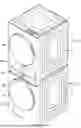

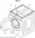
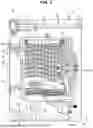

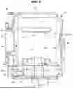
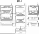
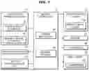


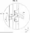


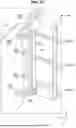
Sources:
- United States Patent and Trademark Office - verify current appl. status at the USPTO↗
Similar patent applications:
- » 20230183906
CLOTHING TREATMENT SYSTEM AND CLOTHING TREATMENT DEVICE - » 20230052184
CONTROL METHOD FOR SMART CLOTHES TREATMENT SYSTEM - » 20210054554
Operation control method and system for clothing treatment device, clothing treatment device, and storage medium - » 20250109897
COMPRESSION SYSTEM AND CLOTHING TREATMENT DEVICE INCLUDING SAME - » 20220042231
Clothing treatment apparatus and online system
Recent applications in this class:
- » 20250223751 2025-07-10
DRYER - » 20250198077 2025-06-19
DEVICE AND METHOD FOR RADIO FREQUENCY DRYING - » 20250188671 2025-06-12
CLOTHING DRYER INCLUDING HEATER - » 20250027264 2025-01-23
AIR HEATER FOR FRONT LOAD WASHING MACHINE - » 20240426044 2024-12-26
GARMENT PROCESSING DEVICE - » 20240141579 2024-05-02
INDUCTION HEATING SYSTEM FOR A DRYER APPLIANCE - » 20240026599 2024-01-25
LAUNDRY TREATING APPARATUS - » 20230407550 2023-12-21
CLOTHES DRYER - » 20230340716 2023-10-26
DRYER AND METHOD FOR OPERATING SAME - » 20230265600 2023-08-24
THERMAL STORAGE MECHANISM FOR A LAUNDRY APPLIANCE THAT UTILIZES RECOVERY HEAT AND RENEWABLE ENERGY SOURCES
Recent applications for this Assignee:
- » 20250261565 2025-08-14
MAGNETIC TUNNELING JUNCTION DEVICE AND MEMORY DEVICE INCLUDING THE SAME - » 20250261494 2025-08-14
DISPLAY APPARATUS AND ASSEMBLY METHOD THEREOF - » 20250261468 2025-08-14
IMAGE SENSOR - » 20250261453 2025-08-14
SEMICONDUCTOR DEVICE - » 20250261431 2025-08-14
METHOD OF MANUFACTURING INTEGRATED CIRCUIT DEVICES - » 20250261402 2025-08-14
POWER SEMICONDUCTOR DEVICES AND METHODS OF FABRICATING THE SAME - » 20250261371 2025-08-14
VERTICAL STRUCTURE MEMORY DEVICE - » 20250261360 2025-08-14
GROUND-CONNECTED SUPPORTS WITH INSULATING SPACERS FOR SEMICONDUCTOR MEMORY CAPACITORS AND METHOD OF FABRICATING THE SAME - » 20250261339 2025-08-14
HEAT DISSIPATING DEVICE - » 20250261094 2025-08-14
ELECTRONIC DEVICE FOR MERGING CLUSTERS OF NAN COMMUNICATION AND OPERATION METHOD THEREOF