TABLE WITH STORAGE FUNCTION
US20250351957A1
2025-11-20
19/200,144
2025-05-06
Smart Summary: A table is designed with a special feature that allows for extra storage. It has a top surface where you can place items and a storage rack that can be pulled out when needed. When not in use, the storage rack can be folded away to save space. The table can also have additional storage options like hanging frames or support racks on the other side. This makes the table more useful for keeping things organized. 🚀 TL;DR
Abstract:
The present subject matter is directed to a table with a storage function, comprising a tabletop and a table frame. The storage rack having an expanded state and a folded state. This table with a storage function allows the storage rack to extend outward in the expanded state to provide a storage function. When using the table, the user can place items not only on the tabletop, but also on the storage rack. Additionally, during storage, the storage rack can be folded and positioned against the table frame without occupying external space. Moreover, in addition to the installation of the storage rack, various other storage structures such as hanging frames and support racks can also be installed on the other side of the table frame, further expanding the table's utility.
Inventors:
- Yixiang Jiang 17 🇨🇳 Yuyao, China
- Jinglei JIANG 36 🇨🇳 Yuyao, China
- Shangxi JIANG 8 🇨🇳 Yuyao, China
Assignee:
- YIXIANG BLOW MOLDING FURNITURE CO., LTD. 16 🇨🇳 Yuyao, China
Applicant:
Interested in similar patents?
Get notified when new applications in this technology area are published.
Classification:
A47B83/04 » CPC main
Combinations comprising two or more pieces of furniture of different kinds Tables combined with other pieces of furniture
A47B3/087 » CPC further
Folding or stowable tables with legs pivoted to top or underframe with foldable top leaves with struts supporting the legs
A47B43/00 » CPC further
Cabinets; Racks; Shelf units; Similar furniture; Similar features of built-in cupboards
A47B43/00 » CPC further
Cabinets, racks or shelf units, characterised by features enabling folding of the cabinet or the like
Description
CROSS-REFERENCES TO RELATED APPLICATIONS
This application claims the priority of CN Patent Application No. 202421092357.2, entitled “Table with Storage Function,” filed May 20, 2024, which is incorporated herein by reference for all purposes.
TECHNICAL FIELD
The present subject matter is in the field of furniture design and manufacture. More particularly, embodiments of the present subject matter relate to a folding table with optional storage.
BACKGROUND
Tables are daily necessities that people frequently use in everyday life, commonly used for placing items, such as dining tables, office desks, etc. Tables generally include a tabletop and a support frame for supporting the tabletop. Under the support of the frame, the tabletop is maintained in a horizontal position so that items can be steadily placed on the tabletop. When a table is arranged for placing items, it occupies a certain amount of space indoors. For those tables that have only a tabletop and a frame, the space below the tabletop is difficult to utilize for placing items, thus resulting in a waste of indoor space. With the continuous improvement of people's quality of life, the functional requirements for tables are increasing. In order to save and fully utilize indoor space, some tables have accommodation devices, such as drawers, arranged in the space below the tabletop, which are used to place items and utilize the space under the tabletop.
However, existing accommodation devices for tables have many drawbacks. First, accommodation devices such as drawers are mostly installed directly or indirectly below the tabletop, making the whole table rather bulky. Moreover, to ensure the table can be used for a long time, the accommodation devices are generally sturdy and durable, which also makes the table relatively heavy. Second, the existing accommodation devices for tables are often fixed in a preset position. Once the accommodation device is removed, a hole will be left on the table, thus affecting the overall appearance of the table. Furthermore, after the accommodation device is disassembled from the table, the support of the tabletop is often affected. Finally, for foldable tables, when folded, the accommodation device is often sturdy and heavy with a fixed shape, so when it is used in conjunction with a foldable table, it can affect the folding of the foldable table. In summary, there is a need to further improve the existing tables with storage functions.
SUMMARY OF THE SUBJECT MATTER
The technical problem to be solved by the present subject matter is to provide a table with a storage function that has a novel structure and a storage rack that can be foldable, in view of the above-mentioned current state of the prior designs.
The technical solution adopted by the present subject matter to solve the above-mentioned problem is: a table with a storage function, comprising a tabletop and a table support provided at the bottom of the tabletop, wherein a storage rack is mounted on the outer side of the table support, the storage rack has an unfolded state and a folded state, and the storage rack unfolds outward from the table support in the unfolded state to provide a storage function, and in the folded state is disposed close to the outer side of the table support.
The storage rack may have various structures. According to one embodiment, the storage rack comprises a storage platform, a first connecting rod, and a second connecting rod, the inner side of the storage platform is rotatably connected to the table support, the first end of the first connecting rod is rotatably connected to the outer side of the storage platform, the first end of the second connecting rod is rotatably connected to the second end of the first connecting rod, and the second end of the second connecting rod is rotatably connected to the table support. Furthermore, the rotation connection point of the second connecting rod to the table support is located above or below the rotation connection point between the storage platform and the table support. With such a configuration, the storage rack can be easily opened and stowed via the rotational connection of the table support, first connecting rod, second connecting rod, and storage platform, which makes operation very convenient. Also, the storage rack can be configured for both upward and downward flipping structures.
According to one embodiment, in the unfolded state of the storage rack, the storage platform is in a horizontal position; in the folded state of the storage rack, the storage platform is in a vertical position and close to the table support.
In order to facilitate placing and retrieving items on the storage rack, in the unfolded state of the storage rack, the outer edge of the storage platform is located outside the corresponding edge of the tabletop.
To enable both the left and right sides of the table to have a storage function, the table support comprises a left table support and a right table support, and the storage rack is installed on both the left and right table supports. As a preferred solution, the table support comprises a left table support and a right table support, and the storage racks are installed on both the left and right table supports.
According to one embodiment, the table support comprises a left table support and a right table support, with the storage rack installed on one of the table supports and a hanging frame installed on the other table support. The hanging frame in the usage state unfolds to the outer side of the corresponding table support, and in the folded state is disposed close to the outer side of the corresponding table support. With such a configuration, the table has a storage rack on one side and a hanging frame on the other, further expanding its usage functionality.
The hanging frame can have various structures. According to one embodiment, the hanging frame includes a hanging frame body and two hanging components. The hanging frame body is rotatably connected to the corresponding table support. Two hanging holes are oppositely provided on the inner wall of the hanging rod of the hanging frame body. The hanging holes have a large opening end and a small opening end. The hanging components have hanging posts and hooks. The hanging posts are inserted from the large opening end into the corresponding hanging holes and are limited inside the small opening end. With this configuration, the hanging components are easy to install and remove. When in use, garbage bags can be hung on the two corresponding hanging components.
To facilitate hanging garbage bags, the hook is provided at the top of the hanging component. In the installed state of the hanging component, the hook protrudes above the hanging frame body.
As one embodiment of the hanging frame, the hanging frame includes a hanging frame body, two hanging components, and a sleeve. Two oppositely arranged hanging holes are opened on the inner wall of the hanging rods of the hanging frame body. The hanging holes have a large opening end and a small opening end. The hanging component has a hanging post protruding toward the corresponding hanging hole and also has a latch. Both ends of the sleeve are limited in the small opening ends of the corresponding hanging holes. The hanging post is limited in the large opening end of the corresponding hanging hole, and the latch snaps onto the wall of the sleeve. With this configuration, the hanging components are easy to install and remove. In use, cylindrical items such as towel rolls can be hung on the sleeve.
According to one embodiment, the top of the hanging component also extends upward to form a hook. With this configuration, the hanging component can be used with the sleeve or separately, expanding the functionality.
According to one embodiment, the table support comprises a left table support and a right table support, with the storage rack installed on one of the table supports, and a support rack installed on the outer part of the other table support. The support rack is detachably connected to the corresponding side of the table support and can be stored on the back of the tabletop in the stowed state. When in use, various items such as thermal containers or snack bags can be placed on the support rack.
To reduce packaging volume, the tabletop comprises a left tabletop and a right tabletop that can be folded with respect to each other. In the folded state of the left and right tabletops, the table support and storage rack are hidden between the left and right tabletops.
To enable the left and right table supports to fold smoothly to the back of the corresponding tabletop, a support crossbar is installed below the joint part of the left and right tabletops. The table support comprises a left table support and a right table support. The left table support is located under the left tabletop and is connected to the support crossbar via a left diagonal rod. The right table support is located under the right tabletop and is connected to the support crossbar via a right diagonal rod.
Compared with the prior designs, the advantages of the present subject matter are: the table with a storage function is provided with a storage rack on the outer side of the table support. In the unfolded state, the storage rack unfolds outward from the table support to provide a storage function. In the folded state, it is positioned close to the outer side of the table support. After the storage rack is installed, the functional use of the table is expanded. When using the table, users can place items not only on the tabletop but also on the storage rack. Moreover, during storage, the storage rack can be folded and placed against the table support without occupying external space or affecting the overall appearance of the table. In addition to installing the storage rack, other types of storage structures such as hanging frames and support racks can also be installed on the other side of the table support, further expanding the table's usage functions.
DESCRIPTION OF DRAWINGS
The present subject matter is illustrated by way of example, and not by way of limitation, in the figures of the accompanying drawings and in which:
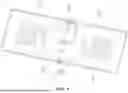
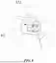
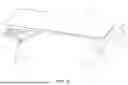
FIG. 1 is a structural schematic diagram of the table according to a first embodiment of the present subject matter (in the state of using the storage rack);
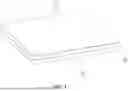
FIG. 2 is a structural schematic diagram of the table according to the first embodiment of the present subject matter (in the folded state of the storage rack);
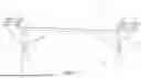
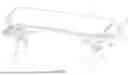
FIG. 3 is a structural schematic diagram of the table shown in FIG. 2 from another angle;
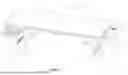
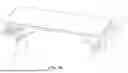
FIG. 4 is a structural schematic diagram of the table according to the first embodiment of the present subject matter (in the folded state of the table support);
FIG. 5 is a structural schematic diagram of the table according to the first embodiment of the present subject matter in the folded state;
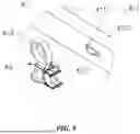
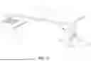
FIG. 6 is a structural schematic diagram of the table according to a second embodiment of the present subject matter;
FIG. 7 is a structural schematic diagram of the table according to a third embodiment of the present subject matter;
FIG. 8 is an enlarged schematic diagram of part A in FIG. 7;
FIG. 9 is a schematic diagram of the installation structure of the hanging component according to the third embodiment of the present subject matter;
FIG. 10 is a structural schematic diagram of the table to a fourth embodiment of the present subject matter;
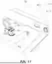
FIG. 11 is a structural schematic diagram of the table to a fifth embodiment of the present subject matter;
FIG. 12 is a partial structural schematic diagram of FIG. 11 with the towel tube removed;
FIG. 13 is a partial assembly schematic diagram of the hanging frame the fifth embodiment of the present subject matter;
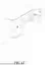
FIG. 14 is a structural schematic diagram of the table to a sixth embodiment of the present subject matter;
FIG. 15 is a structural schematic diagram of the table to a seventh embodiment of the present subject matter; and
FIG. 16 is a structural schematic diagram of the table shown in FIG. 15 from another angle.
DETAILED DESCRIPTION
The present subject matter pertains to improved approaches for a foldable table with optional storages. Embodiments of the present subject matter are discussed below with reference to FIGS. 1-16.
In the following description, for purposes of explanation, numerous specific details are set forth in order to provide a thorough understanding of the present subject matter. It will be apparent, however, to one skilled in the art that the present subject matter may be practiced without some of these specific details. In addition, the following description provides examples, and the accompanying drawings show various examples for the purposes of illustration. Moreover, these examples should not be construed in a limiting sense as they are merely intended to provide examples of embodiments of the subject matter rather than to provide an exhaustive list of all possible implementations. In other instances, well-known structures and devices are shown in block diagram form in order to avoid obscuring the details of the disclosed features of various described embodiments.
Embodiment I
As shown in FIGS. 1 to 5, the table with storage functionality of the present embodiment includes a tabletop 1 and a table support 2 provided at the bottom of the tabletop 1. A storage rack 3 is mounted on the outer side of the table support 2. The tabletop 1 comprises a left tabletop 11 and a right tabletop 12 which can be folded relative to each other. The table support 2 comprises a left table support 21 and a right table support 22. The left table support 21 is mounted at the bottom of the left tabletop 11, and the right table support 22 is mounted at the bottom of the right tabletop 12. There are two storage racks 3 respectively mounted on the left table support 21 and the right table support 22. The storage racks 3 have an unfolded state and a folded state.
In the unfolded state, the storage racks 3 extend outward from the table support 2 to provide a storage function. In the folded state, the storage racks 3 are positioned close to the outer side of the table support 2.
The storage rack 3 of this embodiment comprises a storage platform 30, a first link 31, and a second link 32. The storage platform 30 is configured as a shelf. The inner side of the storage platform 30 is rotatably connected to the table support 2. The first link 31 is located below the second link 32. The first end of the first link 31 is rotatably connected to the outer side of the storage platform 30. The second end of the first link 31 is rotatably connected to the first end of the second link 32. The second end of the second link 32 is rotatably connected to the table support 2. In this embodiment, the rotational connection point of the second link 32 and the table support 2 is located above the rotational connection point of the storage platform 30 and the table support 2. When the storage rack 3 is folded, the storage platform 30 rotates upward.
As shown in FIG. 1, in the unfolded state of the storage rack 3, the first link 31 and the second link 32 lie on the same straight line and are both inclined relative to the horizontal plane. The storage platform 30 is in a horizontal position, and the outer edge of the storage platform 30 is located outside the corresponding edge of the tabletop 1, making it convenient for the user to access items placed on the storage platform 30.
As shown in FIGS. 2 and 3, in the folded state of the storage rack 3, the first link 31 and the second link 32 are both rotated to a vertical position and overlap each other. The storage platform 30 is in a vertical position and close to the table support 2, with the storage platform 30 located outside the first link 31 and the second link 32. At this time, the storage rack 3 does not occupy external space of the table and does not affect the overall appearance of the table, nor does it have any adverse effect on the support of the tabletop 1. Additionally, the front and rear edges of the storage platform 30 have upwardly turned flanges 301. In the folded state of the storage rack 3, the flanges 301 are disposed on the outer side of the table support 2. After providing the flanges 301, items on the storage platform 30 can be prevented from falling off the front and rear sides of the platform.
The table of this embodiment is a folding table. A crossbar 6 is installed below the joint area of the left tabletop 11 and the right tabletop 12. The table support 2 includes the left table support 21 and the right table support 22. The left table support 21 is located under the left tabletop 11, and the right table support 22 is located under the right tabletop 12. The left table support 21 is connected to the crossbar 6 via a left diagonal rod 71, and the right table support 22 is connected to the crossbar 6 via a right diagonal rod 72.
As shown in FIG. 4, the left table support 21 is flipped to the back side of the left tabletop 11, and the right table support 22 is flipped to the back side of the right tabletop 12. This folding structure may refer to existing folding tables and is not elaborated here. As shown in FIG. 5, when the left tabletop 11 and the right tabletop 12 are folded together, the table support 2 and the storage rack 3 are hidden between the left tabletop 11 and the right tabletop 12, making the folding structure of the table very compact.
Embodiment II
As shown in FIG. 6, the difference from Embodiment One lies in that in the present embodiment, the first link 31 is located above the second link 32, and the rotational connection point between the second link 32 and the table support 2 is located below the rotational connection point between the storage platform 30 and the table support 2. When folded, the storage platform 30 rotates downward. The remaining structure of the present embodiment is the same as that of Embodiment One and will not be further described here.
Embodiment III
As shown in FIGS. 7 to 9, with the direction indicated by arrow B as right, in the present embodiment, a storage rack 3 is mounted on the left table support 21. The storage rack 3 can adopt the mounting structure of either Embodiment One or Embodiment Two, and will not be further elaborated here. A hanging frame 4 is mounted on the right table support 22. The hanging frame 4 is rotatably connected to the right table support 22. In the usage state, the hanging frame 4 unfolds to the outside of the right table support 22. In the folded state, it is positioned close to the outer side of the right table support 22.
The hanging frame 4 of the present embodiment includes a hanging frame body 41 and two hanging elements 42. The hanging frame body 41 is rotatably connected to the right table support 22. The rotational connection structure may refer to the rotational connection structure of the storage rack 3, and is not further elaborated here.
Two oppositely arranged hanging holes 411 are provided on the inner walls of the front and rear hanging rods of the hanging frame body 41. The hanging holes 411 each have a large opening end 4111 and a small opening end 4112. The hanging element 42 has a hanging post 421 and a hook 422. The hanging post 421 is inserted into the corresponding hanging hole 411 from the large opening end 4111 and is limited within the small opening end 4112. The hook 422 is provided at the top of the hanging element 42, and in the mounted state of the hanging element 42, the hook 422 protrudes above the hanging frame body 41. As shown in FIG. 7, both ends of the garbage bag 8 are hung on the hooks 422.
Embodiment IV
As shown in FIG. 10, the difference from Embodiment Three is that in the present embodiment, the detachable hanging elements are omitted, and instead, welded hooks 44 are fixedly attached to the hanging frame body. Both ends of the garbage bag 8 are hung on the welded hooks 44.
Embodiment V
As shown in FIGS. 11 to 13, the hanging frame 4 of the present embodiment adds a sleeve 43 on the basis of Embodiment Three. That is, the hanging frame 4 includes a hanging frame body 41, two hanging elements 42, and a sleeve 43. Two oppositely arranged hanging holes 411 are provided on the inner wall of the front and rear hanging rods of the hanging frame body 41. Each hanging hole 411 has a large opening end 4111 and a small opening end 4112. The hanging element 42 protrudes a hanging post 421 toward the corresponding hanging hole 411, and is also equipped with a latch 423. During installation, the two ends of the sleeve 43 are respectively limited within the small opening ends 4112 of the corresponding hanging holes 411, the hanging post 421 is limited within the large opening end 4111 of the corresponding hanging hole 411, and the latch 423 clips onto the wall of the sleeve 43. As shown in FIG. 11, a towel tube 9 is hung on the sleeve 43. In addition, the top of the hanging element 42 in this embodiment also extends upward with a hook 422.
Embodiment VI
As shown in FIG. 14, the present embodiment removes the hanging elements and sleeves, and instead places a support rod 45 across the front and rear hanging rods of the hanging frame body 41. The towel tube 9 is hung on the support rod 45. A limiting structure may be provided between the two ends of the support rod 45 and the front and rear hanging rods to prevent the support rod 45 from falling off.
Embodiment VII
As shown in FIGS. 15 and 16, the present embodiment removes the hanging frame and instead installs a support rack 5 on the right table support 22. The support rack 5 is detachably connected to the right table support 22 and, in the stowed state, can be stored on the back of the tabletop 1. Specifically, the support rack 5 includes a support rack body 51, a lever 52, and a knob 53. The head of the lever 52 has a limiting bar 521, which is positioned on the inner side of the right table support 22. The tail end of the lever 52 is connected to the knob 53. A socket is provided on the table leg of the right table support 22. During installation, first place the support rack 5 horizontally, insert the support rack body 51 into the socket, then rotate the knob 53 so that the limiting bar 521 at the head of the lever 52 rotates to a vertical position and abuts the inner side of the right table support 22. At this point, the limiting bar 521 can further prevent the support rack body 51 from rotating downward, making the limiting structure more reliable.
In the description and claims of the present subject matter, terms indicating directions such as “front”, “rear”, “top”, “bottom”, “left”, “right”, “side”, “top”, and “bottom” are used to describe various exemplary structural parts and elements of the subject matter. However, these terms are used merely for the convenience of illustration, and are defined based on the orientation shown in the accompanying drawings. Since the disclosed embodiments of the present subject matter can be arranged in different directions, these directional terms are for explanatory purposes only and should not be construed as limitations. For example, “top” and “bottom” are not necessarily limited to the directions opposite or consistent with the direction of gravity.
Having disclosed exemplary embodiments and the best mode, modifications and variations may be made to the disclosed embodiments while remaining within the scope of the embodiments of the subject matter as defined by the following claims.
Claims
What is claimed is:1. A table with a storage function, comprising:
a tabletop (1) and a table frame (2) provided at the bottom of the tabletop (1), and
a storage rack (3) mounted on the outer side of the table frame (2), wherein the storage rack (3) has an expanded state and a folded state, and in the expanded state, the storage rack (3) extends outward from the table frame (2) to provide a storage function, and in the folded state, the storage rack (3) is positioned against the outer side of the table frame (2).
2. The table with a storage function of claim 1, wherein the storage rack (3) comprises a storage platform (30), a first link rod (31), and a second link rod (32), the inner side of the storage platform (30) is rotatably connected to the table frame (2), the first end of the first link rod (31) is rotatably connected to the outer side of the storage platform (30), the first end of the second link rod (32) is rotatably connected to the second end of the first link rod (31), the second end of the second link rod (32) is rotatably connected to the table frame (2), and the rotational connection point between the second link rod (32) and the table frame (2) is located above or below the rotational connection point between the storage platform (30) and the table frame (2).
3. The table with a storage function of claim 2, wherein in the expanded state of the storage rack (3), the storage platform (30) is in a horizontal position, and wherein in the folded state of the storage rack (3), the storage platform (30) is in a vertical position and close to the table frame (2).
4. The table with a storage function of claim 3, wherein in the expanded state of the storage rack (3), the outer edge of the storage platform (30) is located outside the corresponding edge of the tabletop (1).
5. The table with a storage function of claim 1, wherein the table frame (2) comprises a left table frame (21) and a right table frame (22), and the storage rack (3) is mounted on both the left table frame (21) and the right table frame (22).
6. The table with a storage function of claim 1, wherein the table frame (2) comprises a left table frame (21) and a right table frame (22), and the storage rack (3) is mounted on one of the left table frame (21) or right table frame (22), and a hanging frame (4) is mounted on the other table frame; the hanging frame (4), in its usage state, extends outward from the corresponding side table frame, and in its folded state, is positioned against the outer side of the corresponding side table frame.
7. The table with a storage function of claim 6, wherein the hanging frame (4) comprises a hanging frame body (41) and two hanging elements (42), the hanging frame body (41) is rotatably connected to the corresponding table frame, two oppositely arranged hanging holes (411) are provided on the inner wall of the hanging rods of the hanging frame body (41), each hanging hole (411) has a large opening end (4111) and a small opening end (4112), and the hanging element (42) comprises a hanging post (421) and a hook (422); the hanging post (421) is inserted from the large opening end (4111) into the corresponding hanging hole (411) and limited within the small opening end (4112).
8. The table with a storage function of claim 7, wherein the hook (422) is provided at the top of the hanging element (42), and in the installed state of the hanging element (42), the hook (422) protrudes above the hanging frame body (41).
9. The table with a storage function of claim 6, wherein the hanging frame (4) comprises a hanging frame body (41), two hanging elements (42), and a sleeve (43), two oppositely arranged hanging holes (411) are provided on the inner wall of the hanging rods of the hanging frame body (41), each hanging hole (411) has a large opening end (4111) and a small opening end (4112), the hanging element (42) protrudes a hanging post (421) toward the corresponding hanging hole (411), the hanging element (42) also has a latch (423), both ends of the sleeve (43) are respectively limited within the small opening ends (4112) of the corresponding hanging holes (411), the hanging post (421) is limited within the large opening end (4111) of the corresponding hanging hole (411), and the latch (423) clips onto the wall of the sleeve (43).
10. The table with a storage function of claim 1, wherein the table frame (2) comprises a left table frame (21) and a right table frame (22), and the storage rack (3) is mounted on one of the left table frame (21) or right table frame (22), and a support frame (5) is mounted on the outer part of the other table frame; the support frame (5) is detachably connected to the corresponding side table frame, and in its storage state, the support frame (5) can be stored on the back of the tabletop (1).
11. A table with a storage function, comprising:
a tabletop;
a table frame disposed beneath the tabletop; and
a storage rack mounted on an outer side of the table frame,
wherein the storage rack is configured to transition between an expanded state and a folded state;
wherein in the expanded state, the storage rack extends outward from the table frame to provide storage functionality; and
wherein in the folded state, the storage rack is positioned adjacent to the outer side of the table frame.
12. The table of claim 11, wherein the storage rack comprises:
a storage platform;
a first link rod; and
a second link rod;
wherein an inner side of the storage platform is rotatably connected to the table frame;
wherein a first end of the first link rod is rotatably connected to an outer side of the storage platform;
wherein a first end of the second link rod is rotatably connected to a second end of the first link rod;
wherein a second end of the second link rod is rotatably connected to the table frame; and
wherein the rotational connection point between the second link rod and the table frame is located above or below the rotational connection point between the storage platform and the table frame.
13. The table of claim 12, wherein:
in the expanded state of the storage rack, the storage platform is disposed in a horizontal position; and
in the folded state of the storage rack, the storage platform is disposed in a vertical position and adjacent to the table frame.
14. The table of claim 13, wherein in the expanded state of the storage rack, an outer edge of the storage platform extends beyond a corresponding edge of the tabletop.
15. The table of claim 11, wherein the table frame comprises a left table frame and a right table frame, and wherein the storage rack is mounted on both the left table frame and the right table frame.
16. The table of claim 11, wherein the table frame comprises a left table frame and a right table frame;
wherein the storage rack is mounted on one of the left table frame or the right table frame; and
wherein a hanging frame is mounted on the other of the left table frame or the right table frame;
wherein the hanging frame is configured to extend outward from the corresponding side table frame in a usage state, and to be positioned against the outer side of the corresponding side table frame in a folded state.
17. The table of claim 16, wherein the hanging frame comprises:
a hanging frame body rotatably connected to the corresponding table frame; and
two hanging elements,
wherein two oppositely arranged hanging holes are formed on an inner wall of hanging rods of the hanging frame body, each of the hanging holes comprising a large opening end and a small opening end;
and wherein each hanging element comprises a hanging post and a hook;
wherein the hanging post is configured to be inserted through the large opening end into the corresponding hanging hole and retained within the small opening end.
18. The table of claim 17, wherein the hook is provided at a top end of each hanging element and is configured to protrude above the hanging frame body in an installed state.
19. The table of claim 16, wherein the hanging frame comprises:
a hanging frame body,
two hanging elements, and
a sleeve,
wherein two oppositely arranged hanging holes are formed on an inner wall of hanging rods of the hanging frame body, each of the hanging holes comprising a large opening end and a small opening end;
wherein each hanging element includes a hanging post configured to extend toward the corresponding hanging hole and a latch;
wherein opposite ends of the sleeve are retained within the small opening ends of the corresponding hanging holes;
wherein the hanging post is retained within the large opening end of the corresponding hanging hole; and
wherein the latch is configured to clip onto a wall of the sleeve.
20. The table of claim 11, wherein the table frame comprises a left table frame and a right table frame;
wherein the storage rack is mounted on one of the left table frame or the right table frame; and
wherein a support frame is mounted on an outer portion of the other of the left table frame or right table frame,
the support frame being detachably connected to the corresponding side table frame and configured to be stored on a rear side of the tabletop in a storage state.
Images & Drawings included:
Sources:
- United States Patent and Trademark Office - verify current appl. status at the USPTO↗
Similar patent applications:
- » 20210085075
Five-device-in-one multi-function multi-configurable hitch-mountable rollable rotatable collapsable tea table, capable of functioning as a pet-kennel, a storage locker, a table, a cooler, and an umbrella base - » 20130054252
Audio processing method and apparatus by utilizing a partition domain spreading function table stored in three linear arrays for reducing storage - » 11511611
Reduction of memory usage for prime number storage by using a table of differences between a closed form numerical function and prime numbers which bounds a prime numeral between two index values - » 20060155845
Method and system for initializing an internal storage table containing access information used by multiple implementations of protocol access functions to extract information from networked devices - » 20210054646
Ten-device-in-one reconfigurable adjustable carport, capable of functioning as privacy screen, wind screen, cabana, dog run, retail-tradeshow booth, attic, storage, picnic table, kennel, and carport
Recent applications in this class:
- » 20240057769 2024-02-22
MULTI-FUNCTION TABLE - » 20230248143 2023-08-10
Artificial Intelligence-Enabled Furniture System with Air Purifier - » 20230090125 2023-03-23
Multi-function table - » 20220378201 2022-12-01
Viral Transmission Barrier for Group Settings - » 20200367647 2020-11-26
MULTI-SURFACE COMFORT TABLE - » 20200275776 2020-09-03
Wishing well table - » 20200054130 2020-02-20
Multi-function table - » 20190183244 2019-06-20
COMBINATION COLLAPSIBLE TABLE PICTURE FRAME - » 20180295986 2018-10-18
Multi-function table - » 20170295930 2017-10-19
Modular laboratory furniture assembly
Recent applications for this Assignee:
- » 20250351958 2025-11-20
COUPLING STRUCTURE FOR TABLES - » 20250351954 2025-11-20
Asymmetrical Multifunctional Folding Table - » 20250333988 2025-10-30
INTEGRATED DOOR ASSEMBLY OF A PREFAB MODULAR SHED - » 20250034891 2025-01-30
PREFAB MODULAR SHED - » 20240352957 2024-10-24
COUPLING STRUCTURE FOR BOARD ASSEMBLY - » 20240268550 2024-08-15
EXPANDABLE FOLDING TABLE WITH REMOVABLE INSERT PANEL ASSEMBLY - » 20230255345 2023-08-17
Expandable folding table with removable insert panel assembly - » 20230157444 2023-05-25
MULTI-FUNCTIONALEXPANDABLE FOLDING TABLE ASSEMBLY - » 20230157443 2023-05-25
EXPANDABLE FOLDING TABLE ASSEMBLY WITH PANELS - » 20230147736 2023-05-11
Expandable folding table with removable insert panel assembly