COUPLING STRUCTURE FOR TABLES
US20250351958A1
2025-11-20
19/200,179
2025-05-06
Smart Summary: A new table design allows two tables to be easily connected. Each tabletop has a groove on the side that faces the other table. To join the tables, a special piece is inserted into both grooves, creating a strong and stable connection. When it's time to separate the tables, you simply pull out the piece, making it quick and easy. This design also lets you connect multiple tables together in different ways as needed. 🚀 TL;DR
Abstract:
The present subject matter is directed to a table coupling structure, comprising a first table and a second table coupled to each other, wherein a respective coupling groove is formed on the coupling side of each tabletop. A coupling member is inserted into the first coupling groove and the second coupling groove to couple the first tabletop and the second tabletop. When coupling the table structure, it is only necessary to insert the coupling member into the first coupling groove and the second coupling groove, thereby enabling the first tabletop and the second tabletop to be coupled together. The connection is firm and stable during use. For disassembly, it only needs to pull out the coupling member, making both coupling and disassembly of the coupling structure convenient. In addition, multiple tables can be connected together as needed, and different coupling methods can be flexibly combined.
Inventors:
- Yixiang Jiang 17 🇨🇳 Yuyao, China
- Jinglei JIANG 36 🇨🇳 Yuyao, China
- Shangxi JIANG 8 🇨🇳 Yuyao, China
Assignee:
- YIXIANG BLOW MOLDING FURNITURE CO., LTD. 16 🇨🇳 Yuyao, China
Applicant:
Interested in similar patents?
Get notified when new applications in this technology area are published.
Classification:
A47B87/002 » CPC main
Sectional furniture, i.e. combinations of complete furniture units, e.g. assemblies of furniture units of the same kind such as linkable cabinets, tables, racks or shelf units Combination of tables; Linking or assembling means therefor
A47B13/083 » CPC further
Details of tables or desks; Table tops; Rims therefor Rims for table tops
A47B13/16 » CPC further
Details of tables or desks; Table tops; Rims therefor Holders for glasses, ashtrays, lamps, candles or the like forming part of tables
A47B87/00 IPC
Sectional furniture, i.e. combinations of complete furniture units, e.g. assemblies of furniture units of the same kind such as linkable cabinets, tables, racks or shelf units
A47B13/08 IPC
Details of tables or desks Table tops; Rims therefor
Description
CROSS-REFERENCES TO RELATED APPLICATIONS
This application claims the priority of CN patent application No. 202421093757.5, entitled “Coupling Structure for Tables,” filed May 20, 2024, which is incorporated herein by reference for all purposes.
TECHNICAL FIELD
The present subject matter is in the field of furniture design and manufacture. More particularly, embodiments of the present subject matter relate to coupling structure for tables or other furniture.
BACKGROUND
Tables are essential furniture in daily life, study, and work. Currently, tables mainly come in two types: fixed and folding. Fixed tables have a shape and size that cannot be changed once the table is manufactured, whereas folding tables can fold their legs or part of the tabletop. When not in use, the table can be folded to save space, and when in use, the table can be unfolded.
However, regardless of whether the table is fixed or foldable, its shape and size are predetermined once manufactured, and cannot be expanded according to different usage needs, resulting in limited flexibility. To solve the problem of table expansion, two tables are sometimes coupled together, but this often leads to relative sliding between the two connected tables, causing inconvenience during use. Moreover, the existing table coupling method is singular and cannot be flexibly adjusted according to the space or position.
In summary, there is a need for connecting tables to provide expanded table surface.
SUMMARY OF THE SUBJECT MATTER
The technical problem to be solved by the present subject matter is to provide a table coupling structure with high connection strength and convenient assembly, addressing the deficiencies of the prior designs.
The technical solution to solve the above problem is as follows: a table coupling structure including a first table and a second table coupled together, where the first table has a first tabletop and the second table has a second tabletop. The coupling side of the first tabletop is provided with a first coupling groove, and the coupling side of the second tabletop is provided with a second coupling groove. A coupling member is inserted into the first and second coupling grooves to connect the first and second tabletops together.
To ensure the coupling member can reliably join the first and second tabletops, both the first and second coupling grooves are strip-shaped grooves. Correspondingly, the coupling member has a rod-shaped inserting portion and a limiting portion provided at the tail of the inserting portion. The rod-shaped inserting portion is inserted into the first and second coupling grooves, forming a coupling gap between the first and second tabletops. The limiting portion is confined within the coupling gap.
To effectively limit the movement between the first and second tabletops, both are provided with arc-shaped corner surfaces. The coupling gap is formed between the arc-shaped corner surfaces of the two tabletops, and the side of the limiting portion has a first arc surface that matches the arc-shaped corner surfaces of the first and second tabletops.
To further enhance the reliability of the connection between the tabletops, the limiting portion is provided with a longitudinal insertion hole. The structure also includes a connecting base, which has a vertically upwardly extending insertion post. The connecting base abuts the lower edge of the arc-shaped corner surfaces of the first and second tabletops, and the insertion post is inserted upward into the longitudinal insertion hole.
Preferably, the side of the connecting base has a second arc surface matching the arc-shaped corner surfaces of the first and second tabletops. This setup allows for better mutual restriction between the first and second tabletops.
The coupling grooves may have various structures. According to one embodiment, both the first and second coupling grooves are T-shaped grooves. Correspondingly, when the grooves are docked, they form an I-shaped structure, and the cross-section of the rod-shaped inserting portion is I-shaped accordingly.
To allow various coupling mechanisms between the first and second tables, the first coupling groove can be provided on the front and rear sidewalls or left and right sidewalls of the first tabletop, and the second coupling groove can be on the front and rear sidewalls or left and right sidewalls of the second tabletop.
Preferably, both the first and second tabletops are rectangular. The short sides of the two tabletops may be joined together, or the short side of one may be connected with the long side of the other, or both long sides may be coupled together.
The present subject matter provides at least the following advantages over the prior designs: The coupling side of the first tabletop is provided with a first coupling groove, and the coupling side of the second tabletop is provided with a second coupling groove. During assembly, the coupling member only needs to be inserted into the first and second coupling grooves to connect the tabletops. The connection is highly secure, and the coupled tabletops are not prone to separation during use. For disassembly, the coupling member can be simply pulled out. Both assembly and disassembly are quick and convenient. Additionally, multiple tables can be connected together as needed, and different coupling methods can be freely combined.
DESCRIPTION OF DRAWINGS
The present subject matter is illustrated by way of example, and not by way of limitation, in the figures of the accompanying drawings and in which:
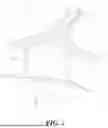
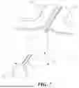
FIG. 1 is a schematic diagram of the table coupling according to a first embodiment of the present subject matter;
FIG. 2 is an enlarged schematic view of part A in FIG. 1;
FIG. 3 is an exploded schematic view of the structure shown in FIG. 2;
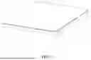
FIG. 4 is a structural schematic diagram of the first tabletop of the first embodiment of the present subject matter;
FIG. 5 is a structural schematic diagram of the second tabletop of the first embodiment of the present subject matter;
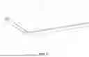
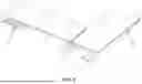
FIG. 6 is a schematic diagram of the table coupling of a second embodiment of the present subject matter;
FIG. 7 is a partial exploded schematic view of the structure shown in FIG. 6;
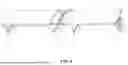
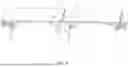
FIG. 8 is a structural schematic diagram of a third embodiment of the present subject matter; and
FIG. 9 is a structural schematic diagram of a fourth embodiment of the present subject matter.
DETAILED DESCRIPTION
The present subject matter pertains to improved approaches for connecting tables or similar furniture. Embodiments of the present subject matter are discussed below with reference to FIGS. 1-9.
In the following description, for purposes of explanation, numerous specific details are set forth in order to provide a thorough understanding of the present subject matter. It will be apparent, however, to one skilled in the art that the present subject matter may be practiced without some of these specific details. In addition, the following description provides examples, and the accompanying drawings show various examples for the purposes of illustration. Moreover, these examples should not be construed in a limiting sense as they are merely intended to provide examples of embodiments of the subject matter rather than to provide an exhaustive list of all possible implementations. In other instances, well-known structures and devices are shown in block diagram form in order to avoid obscuring the details of the disclosed features of various described embodiments.
Embodiment I
As shown in FIGS. 1 to 5, the table coupling structure of this embodiment includes a first table 1 and a second table 2 coupled to each other. The first table 1 has a first tabletop 11, and the second table 2 has a second tabletop 21. A first coupling groove 111 is formed on the coupling side of the first tabletop 11, and a second coupling groove 211 is formed on the coupling side of the second tabletop 21. A coupling member 3 is inserted into the first coupling groove 111 and the second coupling groove 211 to couple the first tabletop 11 with the second tabletop 21.
In this embodiment, both the first coupling groove 111 and the second coupling groove 211 are strip-shaped grooves. Correspondingly, the coupling member 3 has a rod-shaped insertion portion 31 and a limiting portion 32 provided at the rear end of the rod-shaped insertion portion 31. The rod-shaped insertion portion 31 is inserted into the first coupling groove 111 and the second coupling groove 211. In this embodiment, the first coupling groove 111 and the second coupling groove 211 are both T-shaped grooves. Correspondingly, the first coupling groove 111 and the second coupling groove 211 align to form an I-beam-shaped structure, and correspondingly, the cross-section of the rod-shaped insertion portion 31 is I-shaped.
A coupling gap 4 is formed between the first tabletop 11 and the second tabletop 21, and the limiting portion 32 is limited within the coupling gap 4. Specifically, the first tabletop 11 has an arc-shaped corner surface 5, and the second tabletop 21 also has an arc-shaped corner surface 5. A coupling gap 4 is formed between the arc-shaped corner surfaces 5 of the first tabletop 11 and the second tabletop 21. The side surface of the limiting portion 32 has a first arc-shaped surface 321 that matches the arc-shaped corner surfaces 5 of the first tabletop 11 and the second tabletop 21.
The coupling structure of this embodiment further includes a connecting base 6. A vertical insertion hole 322 is formed on the limiting portion 32. The connecting base 6 has an upwardly extending insertion post 61. The connecting base 6 abuts against the lower edges of the arc-shaped corner surfaces 5 of the first tabletop 11 and the second tabletop 21. The insertion post 61 is inserted upward into the vertical insertion hole 322. In addition, the side surface of the connecting base 6 has a second arc-shaped surface 62 that matches the arc-shaped corner surfaces 5 of the first tabletop 11 and the second tabletop 21. In this way, after installation, both the first arc-shaped surface 321 of the limiting portion 32 and the second arc-shaped surface 62 of the connecting base 6 are in contact with the arc-shaped transition surfaces 5 at the coupling gap 4, allowing the coupling member 3 to effectively limit the first tabletop 11 and the second tabletop 21.
In this embodiment, both the first tabletop 11 and the second tabletop 21 are rectangular. The first coupling groove 111 is provided on the short edge of the first tabletop 11, and the second coupling groove 211 is provided on the short edge of the second tabletop 21. The short edge of the first tabletop 11 is coupled to the short edge of the second tabletop 21. Taking the direction indicated by arrow B in FIG. 2 as the right direction, the first coupling groove 111 is formed on the left and right side walls of the first tabletop 11, and the second coupling groove 211 is formed on the left and right side walls of the second tabletop 21. After the first tabletop 11 and the second tabletop 21 are coupled to each other, the length of the tabletop becomes longer, forming a transverse coupling structure.
In this embodiment, a storage slot 7 is formed on the left side of the first tabletop 11 and on the right side of the second tabletop 21. The storage slot 7 can be used to place various items, thereby expanding the functionality of the table. It can also serve as a storage groove to hold items from the tabletop, making the tabletop tidier.
Embodiment II
As shown in FIGS. 6 and 7, the structure of the first table 1 and the second table 2 in this embodiment is the same as that in Embodiment 1. The difference from Embodiment 1 is that after the first table 1 and the second table 2 are coupled in this embodiment, the two storage slots 7 are positioned adjacent to each other.
In addition, the coupling member 3 in this embodiment does not have a connecting base, and the limiting portion 32 also does not have a vertical insertion hole. The rest of the structure is the same as in Embodiment I and will not be described again.
Embodiment III
As shown in FIG. 8, in this embodiment, the first coupling groove 111 is provided on the short edge of the first tabletop 11, and the second coupling groove 211 is provided on the long edge of the second tabletop 21. The short edge of the first tabletop 11 is coupled with the long edge of the second tabletop 21, forming a corner-type coupling structure. The coupling member 3 in this embodiment may be the same as the coupling member in Embodiments I and II.
Embodiment IV
As shown in FIG. 9, in this embodiment, the first coupling groove 111 is provided on the short edge of the first tabletop 11, and the second coupling groove 211 is provided on the short edge of the second tabletop 21. The short edge of the first tabletop 11 is coupled with the short edge of the second tabletop 21, and after coupling, a table with extended length is formed. The coupling member 3 in this embodiment may be the same as the coupling member in Embodiments I and II. The difference from Embodiment I is that in this embodiment, no storage slots are provided on the first tabletop 11 or the second tabletop 21. Instead, additional built-in storage shelfs are provided under both tabletops.
In addition, the long edge of the first tabletop 11 may be coupled with the short edge of the second tabletop 21, or the long edge of the first tabletop 11 may be coupled with the long edge of the second tabletop 21.
In the specification and claims of the present subject matter, directional terms such as “front,” “back,” “upper,” “lower,” “left,” “right,” “side,” “top,” and “bottom” are used to describe various structural parts and elements of the exemplary embodiments of the present subject matter. These terms are used merely for convenience of description and are defined based on the orientations shown in the drawings. Since the embodiments disclosed in the present subject matter may be arranged in different directions, these directional terms are for illustrative purposes only and should not be construed as limiting. For example, “upper” and “lower” are not necessarily limited to directions opposite or aligned with the direction of gravity.
Having disclosed exemplary embodiments and the best mode, modifications and variations may be made to the disclosed embodiments while remaining within the scope of the embodiments of the subject matter as defined by the following claims.
Claims
What is claimed is:1. A table coupling structure, comprising:
a first table having a first tabletop;
a second table having a second tabletop;
wherein a first coupling groove is formed along a coupling side of the first tabletop;
a second coupling groove is formed along a coupling side of the second tabletop; and
a coupling member is configured to be inserted into the first coupling groove and the second coupling groove so as to couple the first tabletop with the second tabletop.
2. The table coupling structure of claim 1, wherein:
the first coupling groove and the second coupling groove are each a strip-shaped groove;
the coupling member comprises a rod-shaped insertion portion and a limiting portion disposed at a rear end of the rod-shaped insertion portion; and
the rod-shaped insertion portion is inserted into the first coupling groove and the second coupling groove.
3. The table coupling structure of claim 2, further comprising:
a coupling gap is formed between the first tabletop and the second tabletop; and
the limiting portion is confined within the coupling gap.
4. The table coupling structure of claim 3, wherein:
the first tabletop includes a first arc-shaped corner surface;
the second tabletop includes a second arc-shaped corner surface;
the coupling gap is formed between the first arc-shaped corner surface and the second arc-shaped corner surface; and
a side surface of the limiting portion comprises a first arc-shaped surface that matches the first and second arc-shaped corner surfaces.
5. The table coupling structure of claim 4, further comprising:
a connecting base, wherein the limiting portion defines a vertical insertion hole;
the connecting base includes an upwardly extending insertion post;
the connecting base abuts against lower edges of the arc-shaped corner surfaces of the first and second tabletops; and
the insertion post is inserted upward into the vertical insertion hole.
6. The table coupling structure of claim 5, wherein:
a side surface of the connecting base comprises a second arc-shaped surface that matches the arc-shaped corner surfaces of the first and second tabletops.
7. The table coupling structure of claim 3, wherein:
the first coupling groove and the second coupling groove are each T-shaped grooves;
the first and second coupling grooves are aligned to form an I-beam-shaped channel; and
a cross-sectional profile of the rod-shaped insertion portion is I-shaped.
8. The table coupling structure of claim 1, wherein:
the first coupling groove is formed on a front, rear, left, or right side wall of the first tabletop; and
the second coupling groove is formed on a front, rear, left, or right side wall of the second tabletop.
9. The table coupling structure of claim 8, wherein:
the first tabletop and the second tabletop are each rectangular;
and wherein the coupling occurs between one or more of:
(a) a short edge of the first tabletop and a short edge of the second tabletop;
(b) a short edge of the first tabletop and a long edge of the second tabletop;
(c) a long edge of the first tabletop and a short edge of the second tabletop; or
(d) a long edge of the first tabletop and a long edge of the second tabletop.
10. A table, comprising:
a first tabletop having a first coupling groove formed along a coupling side of the first tabletop, wherein the first coupling groove is configured to be coupled to a second coupling groove formed on a coupling side of a second tabletop via a coupling member comprising a rod-shaped insertion portion,
wherein the coupling member is configured to be inserted into the first coupling groove and the second coupling groove so as to couple the first tabletop with the second tabletop.
11. The table of claim 10, wherein:
the first coupling groove and the second coupling groove are each a strip-shaped groove;
the coupling member comprises a rod-shaped insertion portion and a limiting portion disposed at a rear end of the rod-shaped insertion portion; and
the rod-shaped insertion portion is inserted into the first coupling groove and the second coupling groove.
12. The table of claim 10, wherein:
the first coupling groove and the second coupling groove are each T-shaped grooves;
the first and second coupling grooves are aligned to form an I-beam-shaped channel; and
a cross-sectional profile of the rod-shaped insertion portion is I-shaped.
13. The table of claim 11, further comprising:
a coupling gap is formed between the first tabletop and the second tabletop; and
the limiting portion is confined within the coupling gap.
14. The table of claim 13, wherein:
the first tabletop includes a first arc-shaped corner surface;
the second tabletop includes a second arc-shaped corner surface;
the coupling gap is formed between the first arc-shaped corner surface and the second arc-shaped corner surface; and
a side surface of the limiting portion comprises a first arc-shaped surface that matches the first and second arc-shaped corner surfaces.
15. The table of claim 14, further comprising:
a connecting base, wherein the limiting portion defines a vertical insertion hole;
the connecting base includes an upwardly extending insertion post;
the connecting base abuts against lower edges of the arc-shaped corner surfaces of the first and second tabletops; and
the insertion post is inserted upward into the vertical insertion hole.
16. The table of claim 15, wherein:
a side surface of the connecting base comprises a second arc-shaped surface that matches the arc-shaped corner surfaces of the first and second tabletops.
17. The table of claim 10, wherein:
the first coupling groove is formed on a front, rear, left, or right side wall of the first tabletop; and
the second coupling groove is formed on a front, rear, left, or right side wall of the second tabletop.
Images & Drawings included:


Sources:
- United States Patent and Trademark Office - verify current appl. status at the USPTO↗
Similar patent applications:
- » 20120104193
Quick coupling structure of leg for table or chair - » 11151892
Programmable logic block with dedicated and selectable lookup table outputs coupled to general interconnect structure - » 20120185704
Data table structure for self-organized management of communication with functional modules coupled via backplane assembly based on received module description including control logic - » 20090293781
Table, Shelf Unit or Modular Structure with Box Hollow Profile Sections, Assembled by Using Safety Coupling Retainers
Recent applications in this class:
- » 20250009126 2025-01-09
WORKSTATION - » 20230017385 2023-01-19
Collapsible platform assembly - » 20200390240 2020-12-17
Snap lock system, method and use for connecting construction elements - » 20200345137 2020-11-05
Concentric circular rotating table(s) - » 20190357677 2019-11-28
Table connection mechanism and method of using the same - » 20190328136 2019-10-31
MODULAR DESK SYSTEMS AND METHODS - » 20190261772 2019-08-29
Adjustable desk with combinative work surface assemblies - » 20190142157 2019-05-16
Extendable table system - » 20190045923 2019-02-14
Table connection mechanism and method of using the same - » 20180049547 2018-02-22
Modular multi-use surface set
Recent applications for this Assignee:
- » 20250351957 2025-11-20
TABLE WITH STORAGE FUNCTION - » 20250351954 2025-11-20
Asymmetrical Multifunctional Folding Table - » 20250333988 2025-10-30
INTEGRATED DOOR ASSEMBLY OF A PREFAB MODULAR SHED - » 20250034891 2025-01-30
PREFAB MODULAR SHED - » 20240352957 2024-10-24
COUPLING STRUCTURE FOR BOARD ASSEMBLY - » 20240268550 2024-08-15
EXPANDABLE FOLDING TABLE WITH REMOVABLE INSERT PANEL ASSEMBLY - » 20230255345 2023-08-17
Expandable folding table with removable insert panel assembly - » 20230157444 2023-05-25
MULTI-FUNCTIONALEXPANDABLE FOLDING TABLE ASSEMBLY - » 20230157443 2023-05-25
EXPANDABLE FOLDING TABLE ASSEMBLY WITH PANELS - » 20230147736 2023-05-11
Expandable folding table with removable insert panel assembly