Autonomous Construction Machine System
US20250376830A1
2025-12-11
19/222,319
2025-05-29
Smart Summary: An autonomous construction machine system is designed to perform various construction tasks. It has a hydraulic arm that can hold different tools, like diggers and augers, which can also use vacuum suction to handle materials. These tools can be easily swapped out, allowing the machine to dig, till, or level ground as needed. A digital tablet allows users to control and set up the machine remotely, while a display screen and control pad are available for on-site adjustments. The machine uses an AI chip to operate the hydraulic arm and tools automatically based on the tasks set through the tablet or screen. 🚀 TL;DR
Abstract:
An autonomous construction machine system is disclosed. The system includes a construction machine equipped with a hydraulic arm that supports modular tool attachments, such as diggers and augers, each featuring vacuum suction for material handling. The tools are interchangeably attached to the hydraulic arm, enabling for a wide range of construction activities, including digging, tilling, and leveling. A digital tablet for facilitating remote operation and configuration of the machine via a wireless communication network is included in the system. The machine also includes a display screen and a control pad, enabling on-site configuration and visualization of tasks. The machine uses AI chip for autonomous operation of the hydraulic arm and the other attachments based on the construction tasks configuration received through the tablet or the screen.
Applicant:
Interested in similar patents?
Get notified when new applications in this technology area are published.
Classification:
E02F9/205 » CPC main
Component parts of dredgers or soil-shifting machines, not restricted to one of the kinds covered by groups - ; Drives; Control devices; Particular purposes of control systems not otherwise provided for Remotely operated machines, e.g. unmanned vehicles
E02F3/88 » CPC further
Dredgers; Soil-shifting machines mechanically-driven with arrangements acting by a sucking or forcing effect, e.g. suction dredgers
E02F9/2045 » CPC further
Component parts of dredgers or soil-shifting machines, not restricted to one of the kinds covered by groups - ; Drives; Control devices; Particular purposes of control systems not otherwise provided for Guiding machines along a predetermined path
E02F9/20 IPC
Component parts of dredgers or soil-shifting machines, not restricted to one of the kinds covered by groups - Drives; Control devices
Description
CROSS-REFERENCE TO RELATED APPLICATION
The present application claims priority to, and the benefit of, U.S. Provisional Application No. 63/656,538, which was filed on Jun. 5, 2024, and is incorporated herein by reference in its entirety.
FIELD OF THE INVENTION
The present invention generally relates to the field of industrial construction machines. More specifically, the present invention relates to a novel industrial machine with a hydraulic arm controlled by an artificial intelligence (AI) chip. The machine can be used for construction tasks. The machine can be configured for construction work using either a digital tablet or using an on-board display screen. The machine is a self-operating machine and is designed to perform a multitude of construction tasks, including but not limited to digging, tilling, and leveling the ground. Accordingly, the present disclosure makes specific reference thereto. Nonetheless, it is to be appreciated that aspects of the present invention are also equally applicable to other like applications, devices, and methods of manufacture.
BACKGROUND
By way of background, traditional landscaping and construction methods rely heavily on manual operation of machinery. Manual operation of equipment inherently places workers in close proximity to moving parts and potential hazards. The proximity can lead to serious injuries such as lacerations, crushing, and even fatalities. Also, different landscaping machinery requires specialized training and skillsets. Projects involving diverse equipment types necessitate a workforce with a broader range of expertise. Unavailability of adequately trained personnel for specific machinery can cause delays. Any operational issue with machinery due to manual use can significantly disrupt project timelines. Landscaping projects often have tight deadlines, and equipment downtime can translate into delays and increased costs.
Even with proper training, human error is a factor in construction projects. Mistakes in measurement and dimensioning can lead to rework, wasted materials, and project delays. Skilled labor is a significant cost factor in landscaping projects. The need for a large workforce can inflate project budgets and limit profit margins. Construction companies desire improved construction machines that reduces dependency on human resources for operating different construction machines.
Conventional construction machines support only limited types of attachments and tools. Construction sites require multiple machines supporting different attachments which is expensive and difficult to manage. Individuals desire an improved construction machine that can support multiple tools to accommodate requirements of different users.
Therefore, there exists a long felt need in the art for an autonomous construction machine. There is also a long felt need in the art for an improved construction machine that utilizes artificial intelligence for autonomous digging, tilling, leveling the ground, and more. Additionally, there is a long felt need in the art for a novel construction machine that reduces physical proximity of operators with the machine by enabling operators to provide specific instructions to the machine through a smart device like a tablet. Moreover, there is a long felt need in the art for an improved construction machine that can support different detachable tools and attachments. Further, there is a long felt need in the art of a specially designed autonomous construction machine system that enables users to operate the machine easily and safely, ensuring the job is completed efficiently and as quickly as possible. Furthermore, there is a long felt need in the art a construction machine that promotes worker safety, improves operational efficiency, and reduces reliance on manual labor in landscaping tasks. Finally, there is a long felt need in the art for an industrial machine that saves considerable time and manpower on any type of construction site that requires industrial machinery.
The subject matter disclosed and claimed herein, in one embodiment thereof, comprises an autonomous construction machine system. The system further comprises an artificial intelligence (AI) controlled machine capable of performing tasks including digging, tilling, and leveling ground. A display screen is disposed on the machine for displaying areas scanned by a sensor and for receiving configuration of construction tasks by a user. A hydraulic arm is equipped with a modular attachment system for various tools, including a vacuum suction mechanism for material transfer to an onboard storage chamber. A digital tablet is wirelessly coupled with the machine for providing remote configuration and operation of the machine. The hydraulic arm features a hinge and a hydraulic cylinder for different movements and is equipped with a modular hook at the distal end thereof for attaching various tools. Each tool integrates vacuum suction capabilities that connect to an onboard vacuum storage chamber for efficient material handling.
In this manner, the autonomous construction machine system of the present invention accomplishes all of the forgoing objectives and provides users with a construction machine that is AI based and decreases the need for a large labor force, reduces labor costs and mitigates issues related to labor shortages in the construction industry. The system automates the potentially hazardous tasks, thereby minimizes human exposure to dangerous conditions, such as operating heavy machinery or working in unstable terrain. The digital tablet interface enables for remote operation and configuration of the machine, offering convenience and flexibility in managing construction tasks without needing to be physically present on-site. The vacuum suction feature for material handling and the onboard storage chamber streamlines the process of collecting, storing, and disposing of materials, making site clean-up more efficient and less disruptive.
SUMMARY OF THE INVENTION
The following presents a simplified summary in order to provide a basic understanding of some aspects of the disclosed innovation. This summary is not an extensive overview, and it is not intended to identify key/critical elements or to delineate the scope thereof. Its sole purpose is to present some general concepts in a simplified form as a prelude to the more detailed description that is presented later.
The subject matter disclosed and claimed herein, in one embodiment thereof, comprises an autonomous construction machine system. The system further comprises an artificial intelligence (AI) controlled machine capable of performing tasks including digging, tilling, and leveling ground. A display screen is disposed on the machine for displaying areas scanned by a sensor and for receiving configuration of construction tasks by a user. A hydraulic arm is equipped with a modular attachment system for various tools, including a vacuum suction mechanism for material transfer to an onboard storage chamber. A digital tablet is wirelessly coupled with the machine for providing remote configuration and operation of the machine.
In another aspect, an AI enabled modular construction machine system is disclosed. The machine system includes a construction machine equipped with AI and sensor technology for autonomous operation across various terrains. A set of detachable tools such as a tiller, rake, and various digging and grading attachments, each with integrated vacuum suction capabilities are attached to the machine. The machine includes integrated sensors and 3D stie scanning using LiDAR, GPS, and stereo camera technology for environmental mapping and obstacle detection, enhancing autonomous operation safety and efficiency. A hydraulic arm with a modular attachment point for tool interchangeability is included, enabling customization of the machine's functionality for specific construction tasks.
In yet another embodiment, an autonomous construction machine system, designed to improve efficiency and accuracy in construction and landscaping tasks through the integration of artificial intelligence (AI) and advanced sensor technology is disclosed. The machine system includes a self-operating machine equipped with a hydraulic arm, designed to perform a multitude of construction tasks, including but not limited to digging, tilling, and leveling the ground. The hydraulic arm features a hinge and a hydraulic cylinder for different movements and is equipped with a modular hook at the distal end thereof for attaching various tools. Each tool integrates vacuum suction capabilities that connect to an onboard vacuum storage chamber for efficient material handling. The system includes a digital tablet equipped with a mobile application for remote operation and configuration of the machine. Communication between the machine and the tablet is facilitated through a wireless network.
In a further embodiment, the machine includes an AI chip which is adapted to facilitate automatic movements of different tools and attachments of the machine. The machine is equipped with sensors and 3D stie scanning using LiDAR, GPS, and stereo camera technology for environmental scanning, obstacle detection, and precise measurement of work areas.
In another aspect, a method for operating an autonomous construction machine system is described. The method includes the steps of pairing the construction machine with a digital tablet through a wireless communication network, configuring construction tasks on the tablet, including specifying task locations and types using a dedicated application, transmitting the configured tasks to the machine, where an AI chip processes the information and autonomously directs the machine to execute the tasks using its hydraulic arm and attached tools.
In yet another aspect, a method for configuring a construction operation using an autonomous machine system is described. The method includes the steps of displaying the scanned area around the machine on the integrated display screen, using data from onboard sensors and cameras, configuring operational parameters directly on the display screen, including start and end points, types of construction work, and specific tool requirements, and activating the machine, wherein the AI module directs the execution of configured tasks, adjusting machine movements and tool operations based on real-time environmental data.
Numerous benefits and advantages of this invention will become apparent to those skilled in the art to which it pertains upon reading and understanding of the following detailed specification.
To the accomplishment of the foregoing and related ends, certain illustrative aspects of the disclosed innovation are described herein in connection with the following description and the annexed drawings. These aspects are indicative, however, of but a few of the various ways in which the principles disclosed herein can be employed and are intended to include all such aspects and their equivalents. Other advantages and novel features will become apparent from the following detailed description when considered in conjunction with the drawings.
BRIEF DESCRIPTION OF THE DRAWINGS
The description refers to provided drawings in which similar reference characters refer to similar parts throughout the different views, and in which:
FIG. 1 illustrates a schematic view of the autonomous construction machine system of the present invention in accordance with the disclosed structure;
FIG. 2 illustrates a rear perspective view of the autonomous construction machine of the present invention in accordance with the disclosed structure;
FIG. 3 illustrates a side perspective view of the autonomous construction machine of the present invention in accordance with the disclosed structure;
FIG. 4 illustrates a side perspective view of another embodiment of the autonomous construction machine in accordance with one embodiment of the present invention;
FIG. 5 illustrates a functional block diagram depicting working of the autonomous operation of the autonomous construction machine in accordance with one embodiment of the present invention;
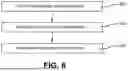
FIG. 6 illustrates a flow chart depicting a process of using the digital tablet for operating the electrical machine in accordance with one embodiment of the present invention; and
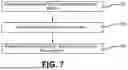
FIG. 7 illustrates a flow chart depicting a process of using the display screen for configuration a construction operation of the machine in accordance with one embodiment of the present invention.
DETAILED DESCRIPTION OF THE PRESENT INVENTION
The innovation is now described with reference to the drawings, wherein like reference numerals are used to refer to like elements throughout. In the following description, for purposes of explanation, numerous specific details are set forth in order to provide a thorough understanding thereof. It may be evident, however, that the innovation can be practiced without these specific details. In other instances, well-known structures and devices are shown in block diagram form in order to facilitate a description thereof. Various embodiments are discussed hereinafter. It should be noted that the figures are described only to facilitate the description of the embodiments. They are not intended as an exhaustive description of the invention and do not limit the scope of the invention. Additionally, an illustrated embodiment need not have all the aspects or advantages shown. Thus, in other embodiments, any of the features described herein from different embodiments may be combined.
As noted above, there is a long felt need in the art for an autonomous construction machine. There is also a long felt need in the art for an improved construction machine that utilizes artificial intelligence for autonomous digging, tilling, leveling the ground, and more. Additionally, there is a long felt need in the art for a novel construction machine that reduces physical proximity of operators with the machine by enabling operators to provide specific instructions to the machine through a smart device like a tablet. Moreover, there is a long felt need in the art for an improved construction machine that can support different detachable tools and attachments. Further, there is a long felt need in the art of a specially designed autonomous construction machine system that enables users to operate the machine easily and safely, ensuring the job is completed efficiently and as quickly as possible. Furthermore, there is a long felt need in the art a construction machine that promotes worker safety, improves operational efficiency, and reduces reliance on manual labor in landscaping tasks. Finally, there is a long felt need in the art for an industrial machine that saves considerable time and manpower on any type of construction site that requires industrial machinery.
The present invention, in one exemplary embodiment, is a method for configuring a construction operation using an autonomous machine system. The method includes the steps of displaying the scanned area around the machine on the integrated display screen, using data from onboard sensors and cameras, configuring operational parameters directly on the display screen, including start and end points, types of construction work, and specific tool requirements, and activating the machine, wherein the AI module directs the execution of configured tasks, adjusting machine movements and tool operations based on real-time environmental data. The system is designed that should the machine fail, it may be driven back to the station manually.
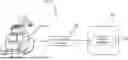
Referring initially to the drawings, FIG. 1 illustrates a schematic view of the autonomous construction machine system of the present invention in accordance with the disclosed structure. The autonomous construction machine system 100 of the present invention is configured to utilize artificial intelligence for digging, tilling, leveling the ground, and more. The autonomous construction system 100 is designed for construction tasks, integrating robotics, artificial intelligence (AI), and various mechanical tools. More specifically, the system 100 includes an autonomous construction machine 102 which can be made in different sizes to accommodate requirements of different users. The construction machine 102 can be powered by a diesel engine 103 (i.e., tier 4 final diesel engine). The other auxiliary systems, for example AI processing unit, sensors/cameras 143, tool switching motors 145, vacuum turbine and hose actuators, et. al., can be powered by a lithium-ion battery pack 105 (i.e., high capacity 60-100 kWh battery pack).
The construction machine 102 is coupled to a digital tablet 108 via a communication network 104. The digital tablet 108 includes a mobile application or software application 106 for configuring and operating the construction machine 102. The digital tablet 108 is preferably a specially designed tablet for controlling the machine 102 and can also be a conventional handheld electronic device with the installed mobile application 106. The mobile application 106 is preferably adapted to pair and control a specific machine 102 and is tagged using the unique identifier of the machine 102.
The communication network 104 can be one or more types of wireless communication signals and/or systems, for example, radio frequency (RF), infrared (IR), frequency-division multiplexing (FDM), orthogonal FDM (OFDM), time-division multiplexing (TDM), time-division multiple access (TDMA), extended TDMA (E-TDMA), wideband CDMA (WCDMA), CDMA 2000, discrete multi-tone (DMT), Bluetooth (®), global positioning system (GPS), Wi-Fi, ZigBee (™), global system for mobile communication (GSM), 2G, 2.5G, 3G, 3.5G, 4G, 5G, 6G or the like.
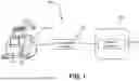
FIG. 2 illustrates a rear perspective view of the autonomous construction machine 102 of the present invention in accordance with the disclosed structure. The rear side (as indicated by the arrow A) of the machine 102 includes a display screen 110 which is adapted to be used for displaying a scanned area 111 and measurements 113 of the scanned area. The scanned area 111 is displayed for planning and executing construction projects by providing precise measurements of the work area. The display screen 110 can display the size of the land enabling a construction foreperson to visually plan the project, marking start and end points for tasks directly on the screen. The display screen 110 enables for manual control or programming of the path and operations of the machine 102.
Along with the display screen 110, a control pad 112 is provided which has a keypad 114 for providing input to the display screen 110 for configuration of a construction location. The machine 102 is designed to be used on all types of terrains and includes a left tread or track 116 and a right tread or track 118. The left tread or track 116 is protected by a left guard 120 and the right tread or track 118 is protected by a right guard 122. It is to be appreciated that the tracks 116, 118 move independently (i.e., via independent hydraulic motors) and comprise rubber or composite steel reinforced tracks. The excavating machine 102 includes a vacuum storage chamber 124 for storing the materials suctioned by different tools and attachments of the machine 102. The storage chamber 124 provides easy and safe storage of the suctioned items/materials, minimizing mess and increasing efficiency. The machine 102 has configurable tread patterns 116, 118 and can operate efficiently on a wide range of terrains, from soft soil to rocky ground.
The vacuum storage chamber 124 includes a first door 126 for removing the stored items. The first door 126 provides easy accessibility of the vacuum storage chamber 124 and is used for cleaning the chamber 124. A hydraulic arm 128 is operatively connected to an AI chamber 130 of the machine 102. The hydraulic arm 128 is adapted to automatically or autonomously move based on a preconfigured construction plan for excavation, digging, and other tasks. The hydraulic arm 128 can support different types of tools and attachments for performing different tasks. It is to be appreciated that hydraulic arm 128 can include an arm-mounted flexible hose or track 1282 routed along the hydraulic arm 128. The hose or track 1282 connects to the active tool and the chamber 124 when vacuum mode is actuated. Debris is sucked or vacuumed through the hose or track 1282 and transferred to a nearby dump truck 1300 via an adjustable outlet or rear-mounted metal discharge pipe 1284.
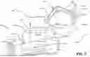
FIG. 3 illustrates a side perspective view of the autonomous construction machine 102 of the present invention in accordance with the disclosed structure. Referring now to FIGS. 2 and 3, the machine 102 on the front side (as indicated by the arrow B) includes a sensor 132 for monitoring the objects around the machine 102 in order to stop the automatic operation of the machine 102. The sensor 132 is also adapted to record and display the land area around the machine 102 on the display screen 110. A second door 134 is disposed in the front portion of the machine 102 and is designed to provide access to the vacuum storage chamber 124 of the machine 102.
The hydraulic arm 128 includes a hydraulic cylinder 140 which includes a hinge 141. The hydraulic cylinder 140 provides the linear movement and the hinge 141 provides the pivotal movement to the hydraulic arm 128. A hook 136 is disposed at the distal end 137 of the hydraulic arm 128 and the hook 136 is designed to detachably accommodate different tools and attachments such as a digging apparatus 138. The hydraulic arm 128 can autonomously switch between different tools using motorized locking pins 141, alignment sensors 143 (i.e., cameras), and a hydraulic or electric actuator 145 to attach/detach tools. Before operating, the system prompts the user to visually confirm, through camera displays on the digital tablet 108, that the tool(s) is properly locked. A selected variety of tools can be stored or docked onboard a tool bay 147 of the autonomous construction machine 102 to be used for a predetermined project.
In one exemplary arrangement, at the rear end of the machine 102, a tiller attachment 142 is detachably attached using the attachment point 144. Different attachments or tools can be attached to the attachment point 144 for enhancing the functionality of the machine 102 for doing all types of construction tasks.
FIG. 4 illustrates a side perspective view of another embodiment of the autonomous construction machine 102 in accordance with one embodiment of the present invention. In the present embodiment, the hook 136 of the hydraulic arm 128 has the detachably attached auger tool 146. The auger tool 146 includes a central suction track 148 for suctioning the material from the land/site and automatically or autonomously transfer to the vacuum storage chamber 124. The hydraulic arm 128 also includes the suction hose or track 1282 for facilitating movement of the materials from the attached tool 146 to the vacuum storage chamber 124. A rake attachment 150 is detachably attached to the machine 102 using the attachment point 144.
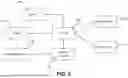
FIG. 5 illustrates a functional block diagram depicting working of the autonomous operation of the autonomous construction machine 102 in accordance with one embodiment of the present invention. The AI module 130 (as shown in FIGS. 3 and 4) includes an AI chip 502 which is a specially designed chip for controlling movements of different tools and attachments attached to the machine 102. The AI chip 502 is adapted to receive input from the sensor 132 for the identified area, land type, and different positions for functioning of the construction work. The AI chip 502 also receives input from integrated LiDAR 506 for identifying underground utilities, potential obstacles, and material types. It is to be appreciated that input can be received from other sources including GPS and stereo cameras. The data received by the AI chip 502 is data is used for precise planning and execution of construction tasks.
The remote signals from the digital tablet 108 as illustrated in FIG. 1 are received by the wireless transceiver 504 of the machine 102. The wireless transceiver 504 establishes the communication network between the machine 102 and the electronic device 108. Based on the inputs received from the sensor 132, electronic device 108, and the LiDAR 506, the AI chip 502 automatically or autonomously moves the hydraulic arm 128 and the other attachment (142, 150) on the rear side of the machine 102.
It will be apparent to a person skilled in the art that the machine 102 does not require manual operation and monitoring for a construction task. The AI chip 502 integration streamlines operations and potentially reduces the need for manual labor for tasks, increasing safety and efficiency on construction sites. The AI chip 502 is capable of handling various tasks from ground preparation (tilling, leveling) to material handling (suctioning and storing materials). The AI chip 502 automatically or autonomously detects and configures the attached tools, adjusting the operational parameters for optimal performance. The AI chip 502 can be adapted to tools for excavation, material handling, grading, and compacting. Exemplary attachments or tools comprise a bucket (shovel), a trenching bucket, a grading bucket, a tilt bucket, an auger, a hydraulic breaker, a ripper, a rake, a grapple, a thumb attachment, a plate compactor, a brush cutter, a vacuum excavation nozzle, a hydraulic shear, pallet forks, a clamshell bucket, a screening bucket, a crusher bucket, a tiller, and a leveler.
FIG. 6 illustrates a flow chart depicting a process of using the digital tablet for operating the electrical machine in accordance with one embodiment of the present invention. Initially, the digital tablet 108 is paired with the machine 102 using the wireless communication channel 104 (Step 602). The digital tablet 108 is preferably paired with a single machine 102 wherein the digital tablet 108 and/or corresponding application 106 provides customized input options for working of the tools and attachments of the machine 102.
Then, using the digital tablet, different construction parameters of a site (i.e., defined task area, type of job, and vacuum preference) are configured (Step 604). The parameters can include but are not limited to dig points, dig depths, dig areas, vacuum actuation, tool selection, starting position, track/path, end position, drilling position, tilling position, and more. The digital tablet can also display a map of the construction site for inputting different configuration parameters. Finally, using the AI chip 502 of the machine 102, based on the received configuration parameters, the autonomous operation of the machine 102 using the movement of the attachments and tools is performed (Step 606).
FIG. 7 illustrates a flow chart depicting a process of using the display screen for configuration a construction operation of the machine in accordance with one embodiment of the present invention. Initially, the area of the land around the machine is displayed on the display screen 110 (Step 702). The area can be displayed using the sensor 132 and one or more cameras (not shown) embedded in the machine 102. Then, different points of work such as starting point, end point, type of construction work, and more are configured on the display screen 110 (Step 704). Finally, the AI chip 502 facilitates the autonomous operation of the machine 102 according to the points/input received by the machine 102 on the display screen 110 (Step 706).
Certain terms are used throughout the following description and claims to refer to particular features or components. As one skilled in the art will appreciate, different persons may refer to the same feature or component by different names. This document does not intend to distinguish between components or features that differ in name but not structure or function. As used herein “autonomous construction machine system”, “autonomous construction system”, and “system” are interchangeable and refer to the autonomous construction machine system 100 of the present invention. Similarly, as used herein, “autonomous construction machine”, “construction machine”, “electric machine”, and “machine” are interchangeable and refer to the autonomous construction machine 102 of the present invention.
Notwithstanding the forgoing, the autonomous construction machine system 100 and the autonomous construction machine 102 of the present invention can be of any suitable size and configuration as is known in the art without affecting the overall concept of the invention, provided that they accomplish the above stated objectives. One of ordinary skill in the art will appreciate that the autonomous construction machine system 100 and the autonomous construction machine 102 as shown in the FIGS. are for illustrative purposes only, and that many other sizes and shapes of the autonomous construction machine system 100 and the autonomous construction machine 102 are well within the scope of the present disclosure. Although the dimensions of the autonomous construction machine system 100 and the autonomous construction machine 102 are important design parameters for user convenience, the autonomous construction machine system 100 and the autonomous construction machine 102 may be of any size that ensures optimal performance during use and/or that suits the user's needs and/or preferences.
Various modifications and additions can be made to the exemplary embodiments discussed without departing from the scope of the present invention. While the embodiments described above refer to particular features, the scope of this invention also includes embodiments having different combinations of features and embodiments that do not include all of the described features. Accordingly, the scope of the present invention is intended to embrace all such alternatives, modifications, and variations as fall within the scope of the claims, together with all equivalents thereof.
What has been described above includes examples of the claimed subject matter. It is, of course, not possible to describe every conceivable combination of components or methodologies for purposes of describing the claimed subject matter, but one of ordinary skill in the art may recognize that many further combinations and permutations of the claimed subject matter are possible. Accordingly, the claimed subject matter is intended to embrace all such alterations, modifications and variations that fall within the spirit and scope of the appended claims. Furthermore, to the extent that the term “includes” is used in either the detailed description or the claims, such term is intended to be inclusive in a manner similar to the term “comprising” as “comprising” is interpreted when employed as a transitional word in a claim.
Claims
What is claimed is:1. An autonomous construction machine system comprising:
a construction machine;
a digital tablet;
a communication network; and
a mobile application;
wherein said mobile application and said digital table autonomously control said construction machine;
wherein said digital tablet is a handheld electronic device;
wherein said construction machine having a unique identifier for pairing with said mobile application;
wherein said mobile application is operated by said digital tablet to control said construction machine;
wherein said construction machine having a rear side including a display screen for displaying a scanned area;
wherein said scanned area having scanned measurements;
wherein said scanned measurements having project planning measurements of a work area;
wherein said display screen displaying said work area;
wherein said project planning measurements and said display screen for an operator to program an autonomous project plan; and
further wherein said autonomous project plan having at least a start point, an end point, and a path for operation of said construction machine.
2. The autonomous construction machine system of claim 1, wherein said construction machine having a control pad including a keypad for inputting commands to said display screen and said construction machine.
3. The autonomous construction machine system of claim 1, wherein said construction machine having a left tread, a left guard, a right tread, and a right guard, and further wherein said left guard protects said left tread and said right guard protects said right tread.
4. The autonomous construction machine system of claim 3, wherein said construction machine having a vacuum storage chamber for storing materials suctioned by said construction machine.
5. The autonomous construction machine system of claim 4, wherein said construction machine having a hydraulic arm operable by said autonomous project plan.
6. The autonomous construction machine system of claim 5, wherein said hydraulic arm having a plurality of attachable tools selected from the group consisting of a bucket, a trenching bucket, a grading bucket, a tilt bucket, an auger, a hydraulic breaker, a ripper, a rake, a grapple, a thumb attachment, a plate compactor, a brush cutter, a vacuum excavation nozzle, a hydraulic shear, pallet forks, a clamshell bucket, a screening bucket, a crusher bucket, a tiller, and a leveler.
7. The autonomous construction machine system of claim 6, wherein said communication network is a wireless communication system selected from the group consisting of one or more of a radio frequency (RF), an infrared (IR), a frequency-division multiplexing (FDM), an orthogonal FDM (OFDM), a time-division multiplexing (TDM), a time-division multiple access (TDMA), an extended TDMA (E-TDMA), a wideband CDMA (WCDMA), a CDMA 2000, a discrete multi-tone (DMT), a Bluetooth (®), a global positioning system (GPS), a Wi-Fi, ZigBee (™), a global system for mobile communication (GSM), a 2G, a 2.5G, a 3G, a 3.5G, a 4G, a 5G, and a 6G.
8. An autonomous construction machine system comprising:
a construction machine;
a digital tablet;
a communication network;
a mobile application; and
a sensor;
wherein said mobile application and said digital table autonomously control said construction machine;
wherein said digital tablet is a handheld electronic device;
wherein said construction machine having a unique identifier for pairing with said mobile application;
wherein said mobile application is operated by said digital tablet to control said construction machine;
wherein said construction machine having a rear side including a display screen for displaying a scanned area;
wherein said scanned area having scanned measurements;
wherein said scanned measurements having project planning measurements of a work area;
wherein said display screen displaying said work area;
wherein said project planning measurements and said display screen for an operator to program an autonomous project plan;
wherein said autonomous project plan having at least a start point, an end point, and a path for operation of said construction machine;
wherein said sensor monitors objects around said construction machine; and
further wherein said sensor records said work area and displays said work area around said construction machine on said display screen.
9. The autonomous construction machine system of claim 8, wherein said construction machine having a control pad including a keypad for inputting commands to said display screen and said construction machine.
10. The autonomous construction machine system of claim 8, wherein said construction machine having a left tread, a left guard, a right tread, and a right guard, and further wherein said left guard protects said left tread and said right guard protects said right tread.
11. The autonomous construction machine system of claim 8, wherein said construction machine having a vacuum storage chamber for storing materials suctioned by said construction machine.
12. The autonomous construction machine system of claim 8, wherein said construction machine having a hydraulic arm operable by said autonomous project plan.
13. The autonomous construction machine system of claim 12, wherein said hydraulic arm having a plurality of attachable tools selected from the group consisting of a bucket, a trenching bucket, a grading bucket, a tilt bucket, an auger, a hydraulic breaker, a ripper, a rake, a grapple, a thumb attachment, a plate compactor, a brush cutter, a vacuum excavation nozzle, a hydraulic shear, pallet forks, a clamshell bucket, a screening bucket, a crusher bucket, a tiller, and a leveler.
14. An autonomous construction machine system comprising:
a construction machine having a hydraulic arm;
a digital tablet;
a communication network;
a mobile application;
a sensor; and
a selectable tool;
wherein said mobile application and said digital table autonomously control said construction machine;
wherein said digital tablet is a handheld electronic device;
wherein said construction machine having a unique identifier for pairing with said mobile application;
wherein said mobile application is operated by said digital tablet to control said construction machine;
wherein said construction machine having a rear side including a display screen for displaying a scanned area;
wherein said scanned area having scanned measurements;
wherein said scanned measurements having project planning measurements of a work area;
wherein said display screen displaying said work area;
wherein said project planning measurements and said display screen for an operator to program an autonomous project plan;
wherein said autonomous project plan having at least a start point, an end point, and a path for operation of said construction machine;
wherein said sensor records said work area and displays said work area around said construction machine on said display screen; and
further wherein said hydraulic arm having a central suction track for suctioning material from said work area and autonomous transfer to a vacuum storage chamber.
15. The autonomous construction machine system of claim 14, wherein said construction machine having a control pad including a keypad for inputting commands to said display screen and said construction machine.
16. The autonomous construction machine system of claim 15, wherein said construction machine having a left tread, a left guard, a right tread, and a right guard, and further wherein said left guard protects said left tread and said right guard protects said right tread.
17. The autonomous construction machine system of claim 14, wherein said construction machine having said vacuum storage chamber for storing materials suctioned by said central suction track.
18. The autonomous construction machine system of claim 14, wherein said construction machine having a hydraulic arm operable by said autonomous project plan.
19. The autonomous construction machine system of claim 14, wherein said sensor monitors objects around said construction machine.
20. The autonomous construction machine system of claim 18, wherein said selectable tool mounted to said hydraulic arm, and further wherein said selectable tool selected from the group consisting of a bucket, a trenching bucket, a grading bucket, a tilt bucket, an auger, a hydraulic breaker, a ripper, a rake, a grapple, a thumb attachment, a plate compactor, a brush cutter, a vacuum excavation nozzle, a hydraulic shear, pallet forks, a clamshell bucket, a screening bucket, a crusher bucket, a tiller, and a leveler.
Images & Drawings included:


Sources:
- United States Patent and Trademark Office - verify current appl. status at the USPTO↗
Recent applications in this class:
- » 20250347088 2025-11-13
WORK MACHINE REMOTE CONTROL SYSTEM - » 20250333932 2025-10-30
WORK VEHICLE WITH DETACHABLE CONTROL THAT CHANGES OPERATION BASED ON SIGNAL FROM PLATFORM SENSOR - » 20250290285 2025-09-18
REMOTE CONTROLLED CONSTRUCTION EQUIPMENT WITH A POWER SUPPLY DIAGNOSTICS FUNCTION - » 20250277352 2025-09-04
AUTONOMOUS OPERATION BY EARTH-MOVING VEHICLE BASED ON TRIGGERING CONDITIONS - » 20250270790 2025-08-28
REMOTE OPERATION SUPPORT SYSTEM AND REMOTE OPERATION SUPPORT METHOD - » 20250263906 2025-08-21
CONTROL OF MULTIPLE POWER MACHINES - » 20250257549 2025-08-14
AUTOMATIC DRIVING SYSTEM FOR WORK MACHINE - » 20250230632 2025-07-17
SYSTEM AND METHOD FOR CONTROLLING WORK MACHINE - » 20250207360 2025-06-26
WORKING MACHINE, AND REMOTE-CONTROL SYSTEM FOR WORKING MACHINE - » 20250188707 2025-06-12
WORK MACHINE AND REMOTE OPERATION SYSTEM OF WORK