FOUR-FOLD ELECTRIC BED
US20260013645A1
2026-01-15
19/331,084
2025-09-17
Smart Summary: A four-fold electric bed is designed to fold easily for storage and convenience. It has different parts, including a headboard, footboard, and several bed plates that can be folded in various ways. The front and rear sections can fold onto each other, making the bed compact. The headboard can also fold down on top of the backrest, while the footboard folds under the leg section. This design allows for a space-saving solution that is easy to use. 🚀 TL;DR
Abstract:
A four-fold electric bed is provided, and belongs to the technical field of folding beds. The four-fold electric bed includes a rear supporting frame, a front supporting frame, a front hip bed plate, a rear hip bed plate, a leg bed plate, a footboard, a backrest bed plate, a headboard, a first driving member, and a second driving member. The front hip bed plate and the leg bed plate form a first folding unit, and the rear hip bed plate and the backrest bed plate form a second folding unit. The second folding unit can be folded to a bottom of the first folding unit. The headboard can be folded to a top of the backrest bed plate. The footboard can be folded to a bottom of the leg bed plate.
Applicant:
Interested in similar patents?
Get notified when new applications in this technology area are published.
Classification:
A47C19/122 » CPC main
Bedsteads; Folding bedsteads foldable head to foot only
A47C20/041 » CPC further
Head -, foot -, or like rests for beds, sofas or the like with adjustable inclination by electric motors
A47C19/12 IPC
Bedsteads Folding bedsteads
A47C20/04 IPC
Head -, foot -, or like rests for beds, sofas or the like with adjustable inclination
Description
TECHNICAL FIELD
The present disclosure relates to the technical field of folding beds, and in particular, to a four-fold electric bed.
BACKGROUND
Chinese utility model patent No. CN223008781U discloses a double-motor folding bed, which includes a first bearing frame, a second bearing frame, a front hip bearing plate, a first lifting assembly, a back bearing plate, a rear hip bearing plate, a second lifting assembly, leg bearing plates, and a foot bearing plate. One side of the second bearing frame is connected to one side of the first bearing frame. The front hip bearing plate is arranged on the first bearing frame and is located on one side close to the second bearing frame. The first lifting assembly is arranged inside the first bearing frame. The back bearing plate is arranged on a first lifting frame. The rear hip bearing plate is arranged on the second bearing frame and is located on one side close to the first bearing frame. The second lifting assembly is arranged inside the second bearing frame. The foot bearing plate is arranged on a second lifting frame. The foot bearing plate is arranged on a third lifting frame.
However, the above double-motor folding bed can only implement two-layer folding during folding, and a volume after folding is still large, which will occupy a large storage space. Therefore, a four-fold electric bed is provided.
SUMMARY
The present disclosure aims to provide a four-fold electric bed, to solve or at least relieve one or more of the above problems in the existing art and problems in other aspects.
To achieve the above objectives, main technical solutions used by the present disclosure are as follows:
A four-fold electric includes a rear supporting frame and a front supporting frame.
A top of one end of the rear supporting frame is fixedly connected with a rear hip bed plate. A top of one end of the front supporting frame is fixedly connected with a front hip bed plate. The front hip bed plate is hinged with the rear hip bed plate through a first hinge member.
One side of the front hip bed plate that is away from the rear hip bed plate is hinged with a leg bed plate. One side of the leg bed plate that is away from the front hip bed plate is hinged with a footboard through a second hinge member.
One side of the rear hip bed plate that is away from the front hip bed plate is hinged with a backrest bed plate. One side of the backrest bed plate that is away from the rear hip bed plate is hinged with a headboard through a third hinge member.
A first driving member for driving the backrest bed plate to rotate upwards is arranged at a bottom of the rear hip bed plate.
A second driving member for driving the leg bed plate to rotate upwards is arranged at a bottom of the front hip bed plate.
The front hip bed plate and the leg bed plate form a first folding unit, and the rear hip bed plate and the backrest bed plate form a second folding unit. The second folding unit can be folded to a bottom of the first folding unit. The headboard can be folded to a top of the backrest bed plate. The footboard can be folded to a bottom of the leg bed plate.
In the four-fold electric bed according to the present disclosure, the rear supporting frame includes two rear supporting rods. The two rear supporting rods are respectively fixed at two ends of the bottom of the rear hip bed plate. A first mounting slot is provided in one end of each rear supporting rod that is away from the rear hip bed plate. Rear expansion rods are fixedly mounted in the first mounting slots through two groups of first locking bolts. First supporting legs are mounted at bottoms of the rear expansion rods through screws.
In the four-fold electric bed according to the present disclosure, the first driving member includes a first linear actuator. A cylinder of the first linear actuator is fixed at the bottom of the rear hip bed plate. A first cross bar is rotatably connected between the two rear supporting rods. Two ends of the first cross bar are fixedly connected with first push rods. Upper ends of the first push rods are rotatably connected with first rollers. The first rollers are in rolling contact with a bottom of the backrest bed plate. A bottom of one end of the first cross bar is fixedly connected with a first connection base. An end portion of a piston rod of the first linear actuator is hinged with a lower end of the first connection base.
In the four-fold electric bed according to the present disclosure, the front supporting frame includes two front supporting rods. The two front supporting rods are respectively fixed at two ends of the bottom of the front hip bed plate. A second mounting slot is provided in one end of each front supporting rod that is away from the front hip bed plate. Front expansion rods are fixedly mounted in the second mounting slots through two groups of second locking bolts. Second supporting legs are mounted at bottoms of the front expansion rods through screws.
In the four-fold electric bed according to the present disclosure, the second driving member includes a second linear actuator. A cylinder of the second linear actuator is fixed at the bottom of the front hip bed plate. A second cross bar is rotatably connected between the two front supporting rods. Two ends of the second cross bar are fixedly connected with second push rods. Upper ends of the second push rods are rotatably connected with second rollers. The second rollers are in rolling contact with a bottom of the leg bed plate. A bottom of one end of the second cross bar is fixedly connected with a second connection base. An end portion of a piston rod of the second linear actuator is hinged with a lower end of the second connection base.
In the four-fold electric bed according to the present disclosure, the front expansion rods are hinged with the footboard through first connection plates.
In the four-fold electric bed according to the present disclosure, the rear supporting frame and the front supporting frame are both arranged in a splayed manner.
In the four-fold electric bed according to the present disclosure, the rear supporting frame and the front supporting frame are staggered.
In the four-fold electric bed according to the present disclosure, a first motor slot for accommodating a motor of the first linear actuator is reserved in the bottom of the rear hip bed plate; and a second motor slot for accommodating a motor of the second linear actuator is reserved in the bottom of the front hip bed plate.
The present disclosure at least has the following beneficial effects:
By a four-fold design, a storage volume of a bed body can be greatly reduced, so that a storage space is saved, and it is convenient for transportation and handling.
By using he first linear actuator and the second linear actuator as driving members to cooperate with a roller transmission structure, electric angle adjustment on the backrest bed plate and the leg bed plate is implemented, to meet different user needs such as lying down and leaning. The operation is labor-saving, and adjustment precision is high.
The splayed design of the rear supporting frame and the front supporting frame increases a supporting span, lowers a center of gravity, and improves an anti-tilting ability of the bed body in an unfolded state. The staggered arrangement avoids structural interference during folding, thus ensuring a smooth and stable folding process. The cooperation between the hinge members and the locking bolts enhances connection strength of the overall structure.
BRIEF DESCRIPTION OF THE DRAWINGS
The accompanying drawings described herein are used to provide a further understanding of the present disclosure, and form part of the present disclosure. Exemplary embodiments of the present disclosure and descriptions thereof are used to explain the present disclosure, and do not constitute any inappropriate limitation to the present disclosure. In the accompanying drawings:
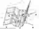
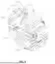
FIG. 1 is a schematic structural diagram of the present disclosure.
FIG. 2 is a schematic structural diagram in another view of the present disclosure.
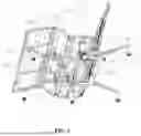
FIG. 3 is a schematic structural diagram I of the present disclosure in a supporting state.
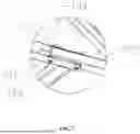
FIG. 4 is an enlarged structural diagram of part A in FIG. 3.
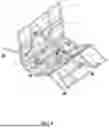
FIG. 5 is a schematic structural diagram II of the present disclosure in a supporting state.
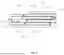
FIG. 6 is an enlarged structural diagram of part B in FIG. 5.
FIG. 7 is an enlarged structural diagram of part C in FIG. 5.
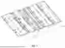
FIG. 8 is a schematic structural diagram of the present disclosure in a folded state.
DESCRIPTION OF REFERENCE NUMERALS
-
- 100: front hip bed plate; 101: rear hip bed plate; 102: first hinge member;
- 200: leg bed plate; 201: second hinge member;
- 300: footboard; 301: first connection plate;
- 400: backrest bed plate;
- 500: headboard; 501: third hinge member;
- 600: rear supporting frame; 601: rear supporting rod; 602: rear expansion rod; 603: first mounting slot; 604: first locking bolt;
- 700: front supporting frame; 701: front supporting rod; 702: front expansion rod; 703: second mounting slot; 704: second locking bolt;
- 800: first linear actuator; 801: first cross bar; 802: first connection base; 803: first push rod; 804: first roller;
- 900: second linear actuator; 901: second cross bar; 902: second connection base; 903: second push rod; and 904: second roller.
DETAILED DESCRIPTION OF THE EMBODIMENTS
The implementations of the present disclosure will be explained in detail below in conjunction with the accompanying drawings and embodiments, so that an implementation process of how to solve the technical problems using the technical means and achieve the technical effects in the present disclosure can be fully understood and implemented.
Referring to FIG. 1 to FIG. 8, an embodiment of the present disclosure provides a four-fold electric bed, including a rear supporting frame 600 and a front supporting frame 700.
A top of one end of the rear supporting frame 600 is fixedly connected with a rear hip bed plate 101. A top of one end of the front supporting frame 700 is fixedly connected with a front hip bed plate 100. The front hip bed plate 100 is hinged with the rear hip bed plate 101 through a first hinge member 102.
One side of the front hip bed plate 100 that is away from the rear hip bed plate 101 is hinged with a leg bed plate 200. One side of the leg bed plate 200 that is away from the front hip bed plate 100 is hinged with a footboard 300 through a second hinge member 201.
One side of the rear hip bed plate 101 that is away from the front hip bed plate 100 is hinged with a backrest bed plate 400. One side of the backrest bed plate 400 that is away from the rear hip bed plate 101 is hinged with a headboard 500 through a third hinge member 501.
A first driving member for driving the backrest bed plate 400 to rotate upwards is arranged at a bottom of the rear hip bed plate 101.
A second driving member for driving the leg bed plate 200 to rotate upwards is arranged at a bottom of the front hip bed plate 100.
The front hip bed plate 100 and the leg bed plate 200 form a first folding unit, and the rear hip bed plate 101 and the backrest bed plate 400 form a second folding unit. The second folding unit can be folded to a bottom of the first folding unit. The headboard 500 can be folded to a top of the backrest bed plate 400. The footboard 300 can be folded to a bottom of the leg bed plate 200.
Relative rotation between the front hip bed plate 100 and the rear hip bed plate 101 is implemented through the first hinge member 102, so that during folding, the front hip bed plate 100 can be folded against the rear hip bed plate 101. The first driving member drives the backrest bed plate 400 to rotate around the rear hip bed plate 101, and the second driving member drives the leg bed plate 200 to rotate around the front hip bed plate 100, to implement angle adjustment on a bed body. During folding, the second folding unit is folded to the bottom of the first folding unit. The headboard 500 is folded and fitted to the top of the backrest bed plate 400 through the third hinge member 501. The footboard 300 is folded and fitted to the bottom of the leg bed plate 200 through the second hinge member 201, thus completing four-fold storage.
In this embodiment, the rear supporting frame 600 includes two rear supporting rods 601. The two rear supporting rods 601 are respectively fixed at two ends of the bottom of the rear hip bed plate 101. A first mounting slot 603 is provided in one end of each rear supporting rod 601 that is away from the rear hip bed plate 101. Rear expansion rods 602 are fixedly mounted in the first mounting slots 603 through two groups of first locking bolts 604. First supporting legs are mounted at bottoms of the rear expansion rods 602 through screws.
The two rear supporting rods 601 provide bottom support for the rear hip bed plate 101. The rear expansion rods 602 are fixed with the rear supporting rods 601 through the first mounting slots 603 and the first locking bolts 604. The first supporting legs at the bottom are in direct contact with the ground to improve stability of the rear supporting frame 600. During folding, one first locking bolt 604 is removed, and the other first locking bolt 604 is loosened. Then, the rear expansion rods 602 are rotatably folded towards the rear supporting rods 601 by using the first locking bolts 604 as axes.
In this embodiment, the first driving member includes a first linear actuator 800. A cylinder of the first linear actuator 800 is fixed at the bottom of the rear hip bed plate 101. A first cross bar 801 is rotatably connected between the two rear supporting rods 601. Two ends of the first cross bar 801 are fixedly connected with first push rods 803. Upper ends of the first push rods 803 are rotatably connected with first rollers 804. The first rollers 804 are in rolling contact with a bottom of the backrest bed plate 400. A bottom of one end of the first cross bar 801 is fixedly connected with a first connection base 802. An end portion of a piston rod of the first linear actuator 800 is hinged with a lower end of the first connection base 802.
When the piston rod of the first linear actuator 800 extends and retracts, the first cross bar 801 is driven to rotate by the first connection base 802. When the first cross bar 801 rotates. The first push rods 803 at the two ends are synchronously lifted up, and the first rollers 804 at the tops of the first push rods 803 roll along the bottom of the backrest bed plate 400 and push the backrest bed plate 400 to rotate upwards, thus implementing backrest angle adjustment. Roller contact reduces frictional resistance in a driving process.
In this embodiment, the front supporting frame 700 includes two front supporting rods 701. The two front supporting rods 701 are respectively fixed at two ends of the bottom of the front hip bed plate 100. A second mounting slot 703 is provided in one end of each front supporting rod 701 that is away from the front hip bed plate 100. Front expansion rods 702 are fixedly mounted in the second mounting slots 703 through two groups of second locking bolts 704. Second supporting legs are mounted at bottoms of the front expansion rods 702 through screws.
The two front supporting rods 701 support the front hip bed plate 100 and form a basic supporting structure of the bed body together with the rear supporting frame 600. The front expansion rods 702 are fixed through the second mounting slots 703 and the second locking bolts 704, and the second supporting legs are in contact with the ground and cooperate with the first supporting legs to ensure overall steadiness of the bed body. During folding, one second locking bolt 704 is removed, and the other second locking bolt 704 is loosened. Then, the front expansion rods 702 are rotatably folded towards the front supporting rods 701 by using the second locking bolts 704 as axes.
In this embodiment, the second driving member includes a second linear actuator 900. A cylinder of the second linear actuator 900 is fixed at the bottom of the front hip bed plate 100. A second cross bar 901 is rotatably connected between the two front supporting rods 701. Two ends of the second cross bar 901 are fixedly connected with second push rods 903. Upper ends of the second push rods 903 are rotatably connected with second rollers 904. The second rollers 904 are in rolling contact with a bottom of the leg bed plate 200. A bottom of one end of the second cross bar 901 is fixedly connected with a second connection base 902. An end portion of a piston rod of the second linear actuator 900 is hinged with a lower end of the second connection base 902.
When the piston rod of the second linear actuator 900 extends and retracts, the second cross bar 901 is driven to rotate by the second connection base 902. The rotation of the second cross bar 901 causes the second push rods 903 to be lifted up, and the second rollers 904 roll along the bottom of the leg bed plate 200 and push the leg bed plate 200 to rotate upwards, thus implementing leg angle adjustment.
In this embodiment, the front expansion rods 702 are hinged with the footboard 300 through first connection plates 301.
The first connection plates 301 form a motion linkage relationship between the front expansion rods 702 and the footboard 300. When the leg bed plate 200 rotates upwards, the footboard 300 flips downwards through the second hinge member 201.
In this embodiment, both the rear supporting frame 600 and the front supporting frame 700 are arranged in a splayed manner.
A splayed structure can increase a transverse span of a supporting bottom surface, lower a center of gravity of the bed body, improve an anti-tilting ability of the bed body in an unfolded state, and reserve an enough space for rotation of the folding units.
In this embodiment, the rear supporting frame 600 and the front supporting frame 700 are staggered.
The staggered layout of the rear supporting frame 600 and the front supporting frame 700 can avoid mechanical interference between the front supporting structure and the rear supporting structure when the second folding unit is downwards folded to the bottom of the first folding unit during folding, thus ensuring a smooth folding process and reducing an overall volume after folding.
In this embodiment, in order to smoothly store a motor of the first linear actuator 800 and a motor of the second linear actuator 900 during folding, a first motor slot for accommodating the motor of the first linear actuator 800 is reserved in the bottom of the rear hip bed plate 101; and meanwhile, a second motor slot for accommodating the motor of the second linear actuator 900 is reserved in the bottom of the front hip bed plate 100.
Working principle: During folding, the first supporting legs and the second supporting legs are first removed, and the first connection plates 301 and the front expansion rods 702 are then separated.
One second locking bolt 704 is removed, and the other second locking bolt 704 is loosened. Then, the front expansion rods 702 are rotatably folded towards the front supporting rods 701 by using the second locking bolts 704 as the axes.
One first locking bolt 604 is removed, and the other first locking bolt 604 is loosened. Then, the rear expansion rods 602 are rotatably folded towards the rear supporting rods 601 by using the first locking bolts 604 as the axes.
Then, the bottom of the front hip bed plate 100 is folded to the bottom of the rear hip bed plate 101. In this case, the rear supporting frame 600, the front supporting frame 700, the first linear actuator 800, and the second linear actuator 900 are sandwiched between the front hip bed plate 100 and the rear hip bed plate 101. Then, the footboard 300 is downwards folded to the bottom of the leg bed plate 200, and the headboard 500 is folded to the top of the backrest bed plate 400.
The above shows and describes several preferred embodiments of the present disclosure, but as mentioned earlier, it should be understood that the present disclosure is not limited to the form disclosed herein and should not be regarded as an exclusion of other embodiments. It can be used in various other combinations, modifications, and environments, and can be changed within the scope of the concept of the present disclosure concept through the above teachings or technologies or knowledge in the related art. All modifications and changes made by a person skilled in the art without departing from the spirit and scope of the present disclosure shall fall within the scope of protection of the claims of the present disclosure.
Claims
What is claimed is:1. A four-fold electric bed, comprising a rear supporting frame and a front supporting frame,
wherein a top of one end of the rear supporting frame is fixedly connected with a rear hip bed plate; a top of one end of the front supporting frame is fixedly connected with a front hip bed plate; the front hip bed plate is hinged with the rear hip bed plate through a first hinge member;
one side of the front hip bed plate that is away from the rear hip bed plate is hinged with a leg bed plate; one side of the leg bed plate that is away from the front hip bed plate is hinged with a footboard through a second hinge member; one side of the rear hip bed plate that is away from the front hip bed plate is hinged with a backrest bed plate; one side of the backrest bed plate that is away from the rear hip bed plate is hinged with a headboard through a third hinge member; a first driving member for driving the backrest bed plate to rotate upwards is arranged at a bottom of the rear hip bed plate; and a second driving member for driving the leg bed plate to rotate upwards is arranged at a bottom of the front hip bed plate.
2. The four-fold electric bed according to claim 1, wherein the front hip bed plate and the leg bed plate form a first folding unit, and the rear hip bed plate and the backrest bed plate form a second folding unit; the second folding unit is folded to a bottom of the first folding unit; the headboard is folded to a top of the backrest bed plate; and the footboard is folded to a bottom of the leg bed plate.
3. The four-fold electric bed according to claim 2, wherein the rear supporting frame comprises two rear supporting rods; the two rear supporting rods are respectively fixed at two ends of the bottom of the rear hip bed plate; a first mounting slot is provided in one end of each rear supporting rod that is away from the rear hip bed plate; rear expansion rods are fixedly mounted in the first mounting slots through two groups of first locking bolts; and first supporting legs are mounted at bottoms of the rear expansion rods through screws.
4. The four-fold electric bed according to claim 3, wherein the first driving member comprises a first linear actuator; a cylinder of the first linear actuator is fixed at the bottom of the rear hip bed plate; a first cross bar is rotatably connected between the two rear supporting rods; two ends of the first cross bar are fixedly connected with first push rods; upper ends of the first push rods are rotatably connected with first rollers; the first rollers are in rolling contact with a bottom of the backrest bed plate; a bottom of one end of the first cross bar is fixedly connected with a first connection base; and an end portion of a piston rod of the first linear actuator is hinged with a lower end of the first connection base.
5. The four-fold electric bed according to claim 1, wherein the front supporting frame comprises two front supporting rods; the two front supporting rods are respectively fixed at two ends of the bottom of the front hip bed plate; a second mounting slot is provided in one end of each front supporting rod that is away from the front hip bed plate; front expansion rods are fixedly mounted in the second mounting slots through two groups of second locking bolts; and second supporting legs are mounted at bottoms of the front expansion rods through screws.
6. The four-fold electric bed according to claim 5, wherein the second driving member comprises a second linear actuator; a cylinder of the second linear actuator is fixed at the bottom of the front hip bed plate; a second cross bar is rotatably connected between the two front supporting rods; two ends of the second cross bar are fixedly connected with second push rods; upper ends of the second push rods are rotatably connected with second rollers; the second rollers are in rolling contact with a bottom of the leg bed plate; a bottom of one end of the second cross bar is fixedly connected with a second connection base; and an end portion of a piston rod of the second linear actuator is hinged with a lower end of the second connection base.
7. The four-fold electric bed according to claim 6, wherein the front expansion rods are hinged with the footboard through first connection plates.
8. The four-fold electric bed according to claim 1, wherein the rear supporting frame and the front supporting frame are both arranged in a splayed manner.
9. The four-fold electric bed according to claim 1, wherein the rear supporting frame and the front supporting frame are staggered.
10. The four-fold electric bed according to claim 6, wherein a first motor slot for accommodating a motor of the first linear actuator is reserved in the bottom of the rear hip bed plate; and a second motor slot for accommodating a motor of the second linear actuator is reserved in the bottom of the front hip bed plate.
Images & Drawings included:


Sources:
- United States Patent and Trademark Office - verify current appl. status at the USPTO↗
Similar patent applications:
- » 20260013644
ULTRA-THIN FOUR-FOLD ELECTRIC BED
Recent applications in this class:
- » 20260013644 2026-01-15
ULTRA-THIN FOUR-FOLD ELECTRIC BED - » 20250375042 2025-12-11
FOLDABLE BEDS - » 20250331649 2025-10-30
Folding Bed - » 20250295242 2025-09-25
FOLDABLE BED - » 20250255416 2025-08-14
BED FRAME FOLDING AND SUPPORTING DEVICE, BED FRAME, AND BED - » 20250248527 2025-08-07
FOLDABLE CONNECTING STRUCTURE FOR BED FRAME - » 20250134267 2025-05-01
FOLDABLE BED - » 20250120512 2025-04-17
REINFORCING STRUCTURE FOR SUPPORTING MIDDLE FOLDING POSITION OF BED FRAME AND BED FRAME - » 20250113921 2025-04-10
Mattress Frame - » 20240382007 2024-11-21
FOLDABLE UNIT AND STACKABLE FRAME HAVING SAME