ACCESSORY HOLDER AND MAINTENANCE STATION SYSTEM
US20260053327A1
2026-02-26
19/376,381
2025-10-31
Smart Summary: An accessory holder and maintenance station helps organize tools for cleaning devices. It has a tray where you can place cleaning accessories. There is also a rod on the side that holds a brush head with an extension rod. This rod has three different positions to hold the brush head in two ways. This design makes it easier to store and access cleaning tools. 🚀 TL;DR
Abstract:
An accessory holder and a maintenance station system. The accessory holder includes: an accommodating tray configured to accommodate an accessory of a surface cleaning device; and an accommodating rod located on one side of the accommodating tray and configured to accommodate a brush head provided with an extension rod, where the accommodating rod includes a first accommodating position, a second accommodating position, and a third accommodating position, the first accommodating position and the second accommodating position implement a first accommodating posture of the brush head, and the first accommodating position and the third accommodating position implement a second accommodating posture of the brush head.
Inventors:
- Qi Wu 3 🇨🇳 Shenzhen, China
- Li'an WANG 3 🇨🇳 Shenzhen, China
- Yongfei ZHOU 3 🇨🇳 Shenzhen, China
- Binxiong LIANG 2 🇨🇳 Shenzhen, China
- Tenglong JIN 1 🇨🇳 Shenzhen, China
- Bingbing JIN 1 🇨🇳 Shenzhen, China
- Lingxing ZENG 1 🇨🇳 Shenzhen, China
Applicant:
Interested in similar patents?
Get notified when new applications in this technology area are published.
Classification:
A47L11/4091 » CPC main
Machines for cleaning floors, carpets, furniture, walls, or wall coverings; Parts or details of machines not groups - , , e.g. handles, arrangements of switches, skirts, buffers, levers Storing or parking devices, arrangements therefor; Means allowing transport of the machine when it is not being used
A47L11/40 IPC
Machines for cleaning floors, carpets, furniture, walls, or wall coverings Parts or details of machines not groups - , , e.g. handles, arrangements of switches, skirts, buffers, levers
Description
CROSS-REFERENCE TO RELATED APPLICATIONS
The present application is a Continuation Application of International Application No. PCT/CN2023/130806, filed on Nov. 9, 2023, which claims priorities to Chinese Patent Application Nos. 202321074111.8 and 202321082695.3, filed on May 6, 2023, both of which are herein incorporated by reference in their entireties for all purposes.
TECHNICAL FIELD
The present application relates to the technical field of surface cleaning devices, in particular to an accessory holder and a maintenance station system, and relates to a holder and a maintenance station system.
BACKGROUND ART
In recent years, with the development of science and technology, a variety of cleaning products have emerged continuously, which have reduced the burden on people in cleaning and sweeping tasks, met their needs and brought great convenience to their lives.
SUMMARY OF THE INVENTION
Embodiments of the present application provide an accessory holder. The accessory holder includes: a storage tray configured to store accessories for a surface cleaning device; and a storage rod located on a side of the storage tray and configured to store a brush head with an extension rod, the storage rod including a first storage position, a second storage position and a third storage position, wherein the first storage position and the second storage position enable a first storage posture of the brush head, and the first storage position and the third storage position enable a second storage posture of the brush head.
In some embodiments, the first storage position is located on a side of the second storage position away from the storage tray; and the third storage position is located on a side of the second storage position close to the storage tray.
In some embodiments, the first storage position, the second storage position and the third storage position are all located on a side of the storage rod facing away from the storage tray.
In some embodiments, the first storage position extends in a direction substantially perpendicular to the storage rod, a first curved storage structure is arranged at a tail end of the first storage position, and the first curved storage structure is configured to store the extension rod of the brush head.
In some embodiments, the second storage position extends in a direction substantially perpendicular to the storage rod, a second curved storage structure is arranged at a tail end of the second storage position, and the second curved storage structure is configured to store an adapter portion of the brush head, wherein the adapter portion has a diameter larger than a diameter of the extension rod.
In some embodiments, the third storage position extends in a direction substantially perpendicular to the storage rod, and a plane where a tail end of the third storage position lies is non-parallel to an axis of the storage rod.
In some embodiments, the plane where the tail end of the third storage position lies is tilted upward relative to the axis of the storage rod.
In some embodiments, the third storage position includes: a support cavity formed by sidewalls that are substantially perpendicular to the storage rod in a surrounding manner; and reinforcing ribs connecting opposing sidewalls of the cavity.
In some embodiments, the first storage posture is such that the brush head is perpendicular to the extension rod, and the second storage position is such that the brush head and the extension rod are substantially coplanar.
In some embodiments, in the first storage posture, the first storage position engages the extension rod, and the second storage position abuts against the adapter portion of the brush head; and in the second storage position, the first storage position engages the extension rod, and the third storage position abuts against a bottom surface of the brush head.
The embodiments of the present application provide a maintenance station system. The maintenance station system includes the accessory holder in any one of the above items.
The embodiments of the present application provide a maintenance station system for a surface cleaning device. The maintenance station system includes: a main holder and an accessory holder. The main holder is configured to support the surface cleaning device, and includes: a tray portion having a first snap-fit structure; and a support portion located on a side of the tray portion, wherein the first snap-fit structure is located on a side of the tray portion facing away from the support portion. The accessory holder is configured to store accessories for the surface cleaning device, and includes: a second snap-fit structure disposed on a side of the accessory holder, and the second snap-fit structure is configured to be in snap-fit connection with the first snap-fit structure, such that the accessory holder is connected to a side of the main holder.
In some embodiments, the first snap-fit structure is located on a side of the tray portion adjacent to the support portion and/or the side of the tray portion where the support portion lies.
In some embodiments, there are three first snap-fit structures, which are located on both sides of the tray portion adjacent to the support portion and the side of the tray portion where the support portion is located, respectively.
In some embodiments, the first snap-fit structure includes: a recessed portion formed along a side edge of the tray portion towards a center direction of the tray portion; and a first snap-fit pattern formed in a preset shape within the recessed portion.
In some embodiments, the recessed portion is of a semi-enclosed structure defined by a first sidewall extending in a vertical direction.
In some embodiments, the first snap-fit pattern is formed by a plurality of second sidewalls extending in a vertical direction.
In some embodiments, the second snap-fit structure is protrudingly formed along a side edge of the accessory holder, and the second snap-fit structure has a second snap-fit pattern, which is mated with the first snap-fit patterning pattern to achieve snap-fit connection.
In some embodiments, after the second snap-fit structure is in snap-fit connection with the first snap-fit structure, the second snap-fit structure is accommodated in the first snap-fit structure.
In some embodiments, the accessory holder includes: a storage tray configured to store accessories for the surface cleaning device; and a storage rod located on a side of the storage tray and configured to store a brush head with an extension rod, wherein the second snap-fit structure is located on a side of the storage tray opposite to the storage rod.
In some embodiments, after the second snap-fit structure is in snap-fit connection with the first snap-fit structure, a side edge of the storage tray substantially abuts a side edge of the tray portion.
Embodiments of the present application provides a holder configured to support a surface cleaning device. The holder includes: a housing including an air inlet and an air outlet; a fan disposed in the housing, the fan including an air intake and an air vent; and a component to be cooled, which is disposed in an airflow passage between the air inlet of the housing and the air intake of the fan, such that heat is taken away from the component to be cooled with the flowing of an airflow.
In some embodiments, the component to be cooled includes: a first component to be cooled and a second component to be cooled, and the airflow passage includes a first gap between the first component to be cooled and the second component to be cooled.
In some embodiments, a geometric center of the air intake is lower than a lower edge of the first gap.
In some embodiments, the air intake is disposed on a back surface of the housing.
In some embodiments, the airflow passage includes a second gap between a surface of the component to be cooled and the back surface of the housing.
In some embodiments, the airflow passage includes two side gaps and/or a bottom gap of the first component to be cooled.
In some embodiments, the holder further includes: a heating component disposed on a side of the air vent of the fan, wherein after exiting the air vent of the fan, an airflow in the airflow passage is heated by the heating component and then exits via the air outlet of the housing.
In some embodiments, the holder further includes: a hot air passage, via which hot air blown from the air outlet of the housing is blown towards a rolling brush.
In some embodiments, the component to be cooled is a circuit board.
BRIEF DESCRIPTION OF THE DRAWINGS
The accompanying drawings here, which are incorporated in and constitute a part of the Description, illustrate embodiments consistent with the present application and, together with the Description, serve to explain the principles of the present application. Apparently, the accompanying drawings in the following description show merely some embodiments of the present application, and a person of ordinary skill in the art may still derive other drawings from these accompanying drawings without creative efforts. In these drawings:
FIG. 1 is a schematic diagram of an overall structure of a maintenance station system according to some embodiments of the present application;
FIG. 2 is a schematic diagram of an overall structure of a main holder according to some embodiments of the present application;
FIG. 3 is a schematic diagram of a bottom structure of the main holder according to some embodiments of the present application;
FIG. 4 is a schematic diagram of an enlarged structure of part A of the main holder according to some embodiments of the present application;
FIG. 5 is a schematic diagram of an overall structure of an accessory holder according to some embodiments of the present application;
FIG. 6 is a schematic diagram of an enlarged structure of part B of the accessory holder according to some embodiments of the present application;
FIG. 7 is a schematic structural diagram of a first storage posture of the accessory holder according to some embodiments of the present application;
FIG. 8 is a schematic structural diagram of a second storage posture of the accessory holder according to some embodiments of the present application;
FIG. 9 is a schematic structural diagram of various storage positions of the accessory holder according to some embodiments of the present application;
FIG. 10 is a schematic diagram of a cross-sectional structure of the main holder according to some embodiments of the present application;
FIG. 11 is a schematic diagram of a partially enlarged cross-sectional structure of the main holder according to some embodiments of the present application;
FIG. 12 is a schematic diagram of a partial back surface structure of the main holder according to some embodiments of the present application; and
FIG. 13 is a schematic diagram of a partial three-dimensional structure of the main holder according to some embodiments of the present application.
DESCRIPTION OF REFERENCE SIGNS
-
- main holder (holder) 100, tray portion 110, first snap-fit structure 111, support portion 120, accessory holder 200, second snap-fit structure 211, recessed portion 1111, first snap-fit pattern 1112, storage tray 210, storage rod 220, edge sidewall 2111, central sidewall 2112, transverse sidewall 2113, first storage position 221, second storage position 222, third storage position 223, brush head 300, storage arm 2211, first curved storage structure 2212, extension rod 310, adapter portion 320, storage plate 2221, support plate 2222, sidewall 2231, reinforcing rib 2232, support cavity 2233, housing 121, air inlet 1211, air outlet 1212, fan 122, air intake 1221, air vent 1222, component to be cooled 123, first component to be cooled 1231, second component to be cooled 1232, first gap 1233, second gap 1234, bottom gap 1235, heating component 124, and hot air passage 125.
DETAILED DESCRIPTION
For clearer descriptions of the objects, technical solutions and advantages in the present application, the present application is further described in detail hereinafter in combination with the accompanying drawings. Obviously, the described embodiments are merely some embodiments, rather than all embodiments, of the present application. Based on the embodiments in the present application, all other embodiments derived by a person of ordinary skill in the art without creative efforts shall fall within the protection scope of the present application.
The terms used in the embodiments of the present application are only for the purpose of describing specific embodiments, but are not intended to limit the present application. The singular forms “a”, “the” and “said” used in the embodiments and the appended claims of the present application are intended to include the plural forms as well, unless otherwise clearly specified in the context. “A plurality of”generally includes at least two.
It should be understood that the term “and/or” as used herein only describes an associated relationship of associated objects, indicating three kinds of relationships. For example, A and/or B can represent that A exists alone, A and B exist concurrently, and B exists alone. In addition, the character “/”herein generally indicates that the associated objects are in an “or”relationship.
It should be understood that although the terms first, second, third, etc. may be used in the embodiments of the present application to describe certain objects, these objects should not be limited by these terms. These terms are only used for a distinguishing purpose. For example, a first object may also be referred to as a second object, and similarly, a second object may also be referred to as a first object, without departing from the scope of the embodiments of the present application.
It should also be noted that the terms “comprise”, “include” or any other variants thereof are intended to cover the nonexclusive inclusion, such that the commodities or apparatuses including a series of elements not only include those elements, but also include other unclearly listed elements, or also include the inherent elements of such commodities or apparatuses. Without more limitations, the element defined by the phrase “including a.” does not exclude the existence of other identical elements in the commodity or apparatus that includes such an element.
The optional embodiments of the present application will be described in detail below with reference to the accompanying drawings.
A maintenance station enables charging, self-cleaning and the like for a surface cleaning device. A maintenance station system of the surface cleaning device includes a main holder (also referred to as a holder subsequently) and an accessory holder. The main holder serves to support the surface cleaning device, and the accessory holder serves to support accessories for the surface cleaning device. The main holder and the accessory holder are of a separable structure. A key factor in user experience is how to set a positional relationship reasonably and conveniently between the main holder and the accessory holder by a user according to the spatial position during use. In addition, how to rationalize the storage structure of the accessory holder has also become the key to the user experience. Furthermore, there are circuit boards and other heat generating component in the holder, and how to dissipate the heat from the circuit board is a technical problem that needs to be solved urgently.
An embodiment of the present application provides a maintenance station system for a surface cleaning device. The maintenance station system includes: a main holder and an accessory holder. The main holder is configured to support the surface cleaning device, and includes: a tray portion having a first snap-fit structure; and a support portion located on a side of the tray portion. The first snap-fit structure is located on a side of the tray portion facing away from the support portion. The accessory holder is configured to store accessories for the surface cleaning device, and includes: a second snap-fit structure disposed on a side of the accessory holder, and the second snap-fit structure is configured to be in snap-fit connection with the first snap-fit structure, such that the accessory holder is connected to a side of the main holder.
According to the maintenance station system of the surface cleaning device provided by the embodiment of the present application, three sides of the main holder are each provided with the first snap-fit structure, such that the accessory holder can be arranged on any side of the main holder through the first snap-fit structure. The accessory holder may be mounted in any of the three positions according to actual use needs, such that a user can place the main holder and the accessory holder as flexibly as possible according to his/her own use needs and space environment, thereby improving space utilization and user experience.
Specifically, an embodiment of the present application provides a maintenance station system for a surface cleaning device. As an example, FIG. 1 is a schematic diagram of an overall structure of a maintenance station system according to some embodiments of the present application; FIG. 2 is a schematic diagram of an overall structure of a main holder according to some embodiments of the present application; FIG. 3 is a schematic diagram of a bottom structure of the main holder according to some embodiments of the present application; and FIG. 4 is a schematic diagram of an enlarged structure of part A of the main holder according to some embodiments of the present application; FIG. 5 is a schematic diagram of an overall structure of an accessory holder according to some embodiments of the present application; and FIG. 6 is a schematic diagram of an enlarged structure of part B of the accessory holder according to some embodiments of the present application.
For clearer description of the behaviors of a self-cleaning maintenance station, as shown in FIG. 2, directions are defined as follows: the main holder can be calibrated by the following three mutually perpendicular axes as defined: a transverse axis Y, a front-rear axis X, and a central vertical axis Z. The direction opposite to the arrow along the front-rear axis X is labeled “rearward”, and the direction of the arrow along the front-rear axis X is labeled “forward”. The transverse axis Y is essentially along the direction of the width of the main holder, the direction of the arrow along the transverse axis Y is the “left side” of the main holder, and the opposite direction of the arrow along the transverse axis Y is the “right side” of the main holder. The vertical axis Z is the direction extending upward along the bottom surface of the main holder, the direction of the arrow along the vertical axis Z is the “upper side” of the main holder, and the direction opposite to the arrow along the vertical axis Z is the “lower side”of the main holder.
Specifically, as shown in FIGS. 1, 2 and 5, an embodiment of the present application provides a maintenance station system for a surface cleaning device. The maintenance station system includes a main holder 100 configured to support the surface cleaning device, and the surface cleaning device includes, for example a handheld floor scrubber, a floor mop, a vacuum cleaner, etc. The main holder 100 includes a tray portion 110 having a first snap-fit structure 111, and further includes a support portion 120 located on a side of the tray portion 110. The first snap-fit structure 111 is located on a side of the tray portion 110 facing away from the support portion 120. The maintenance station system further includes an accessory holder 200 configured to support accessories for the surface cleaning device. The accessory holder 200 includes a second snap-fit structure 211 disposed on a side of the accessory holder 200, and the second snap-fit structure 211 is configured to be in snap-fit connection with the first snap-fit structure 111, such that the accessory holder 200 is connected to a side of the main holder 100.
In some embodiments, the tray portion 110 may be of a structure whose projection on the ground is generally circular, elliptical, rectangular, square, polygonal, or the like, without limitation. This embodiment is described with a rectangle as an example. As shown in FIG. 2, when the projection of the tray portion 110 on the ground is substantially rectangular, the first snap-fit structure 111 is located on any side of the tray portion 110 adjacent to the support portion 120. As an example, when there is one first snap-fit structure 111, the first snap-fit structure 111 is located on the left or right side of the tray portion 110 or the side where the support portion 120 is located; when there are two first snap-fit structures 111, the two first snap-fit structures 111 are located on any two sides of the left and right sides of the tray portion 110 and the side of the tray portion 110 where the support portion 120 is located; and when three first snap-fit structures 111 are included, the three first snap-fit structures 111 are located on the left and right sides of the tray portion 110 and the side of the tray portion 110 where the support portion 120 is located. That is, the first snap-fit structures 111 may be located on any one, two or three sides of the other three sides of the tray portion 110, as long as the first snap-fit structure 111 is not located on the side opposite to the side where the support portion 120 is located. The surface cleaning device needs to be placed on or removed from the side of the tray portion 110 opposite to the side where the support portion 120 is located, and if the accessory holder is arranged on this side after the arrangement of the first snap-fit structure, the placement and removal of the surface cleaning device will be adversely affected. In addition, a drying airflow will be blown out from this side, and the arrangement of the accessory holder on this side will adversely affect the arrangement of an air passage of the tray portion.
In some embodiments, as shown in FIG. 3, there are three first snap-fit structures 111, which are located on both sides of the tray portion 110 adjacent to the support portion 120 and the side of the tray portion 110 where the support portion 120 is located, respectively. The first snap-fit structures are arranged in three positions of the tray portion, such that the accessory holder can be arranged on any side of the main holder via the first snap-fit structures. The accessory holder may be mounted in any one of the three positions according to actual use needs, such that a user can place the main holder and the accessory holder as flexibly as possible according to his/her own use needs and space environment, thereby improving space utilization and user experience.
In some embodiments, as shown in FIGS. 3 and 4, the first snap-fit structure 111 includes a recessed portion 1111, which is formed along one side edge of the tray portion 110 towards the center direction of the tray portion 110. The first snap-fit structure 111 further includes a first snap-fit pattern 1112, which is formed in a preset shape in the recessed portion 1111. The specific shape of the first snap-fit pattern 1112 is not limited, which is, for example, a spiral structure, an elongated strip structure, a short strip structure, etc., and the first snap-fit pattern 1112 has at least one hollowed-out position to facilitate mating and snap-fit connection with the second snap-fit structure.
In some embodiments, as shown in FIG. 4, the recessed portion 1111 is a semi-enclosed structure defined by a first sidewall extending in a vertical direction. The first snap-fit pattern 1112 is formed by a plurality of second sidewalls extending in the vertical direction. The recessed portion 1111 and the sidewalls of the first snap-fit pattern 1112 extend in the vertical direction to facilitate mating and snap-fit connection with the second snap-fit structure.
In some embodiments, as shown in FIG. 5, the second snap-fit structure 211 is protrudingly formed along a side edge of the accessory holder 200, and the second snap-fit structure 211 has a second snap-fit pattern, which is mated with the first snap-fit pattern 1112 to achieve snap-fit connection. As an example, the second snap-fit pattern and the first snap-fit pattern 1112 are in a male-female snap-fit connection. That is, the sidewalls of the second snap-fit pattern extending in the vertical direction are exactly located at the hollowed-out position of the first snap-fit pattern, such that after the second snap-fit structure is snap-fitted in the first snap-fit structure, the second snap-fit structure is accommodated in the first snap-fit structure. For example, the second snap-fit structure may be filled in all the hollowed-out positions of the first snap-fit structure, or partially filled in the hollow-out positions of the first snap-fit structure. The second snap-fit pattern and the first snap-fit pattern are in a male-female snap-fit connection, such that the main holder 100 and the accessory holder 200 are connected more firmly and are less prone to detachment and tipping over. During use, the tray portion 110 is slightly lifted, the second snap-fit structure 211 of the accessory holder 200 extends into the position of the first snap-fit structure 111 under the tray portion 110, and the tray portion 110 is pressed downward, such that the second snap-fit pattern is snap-fitted into the first snap-fit pattern, thereby connecting the accessory holder 200 to one side of the main holder 100. The user may connect the accessory holder 200 to any side of the main holder 100 according to the spatial orientation of the main holder 100.
In some embodiments, as shown in FIG. 5, the accessory holder 200 further includes a storage tray 210 configured to store accessories for the surface cleaning device, and the accessories for the surface cleaning device include, for example, a dust collection cylinder, a roller brush, a brush head, etc. The accessory holder 200 further includes a storage rod 220 located on a side of the storage tray 210 and configured to store a brush head with an extension rod. The second snap-fit structure 211 is located on a side of the storage tray 210 opposite to the storage rod 220. The external form of the second snap-fit structure 211 corresponds to the shape of the recessed portion 1111 of the first snap-fit structure 111, such that after the second snap-fit structure 211 is snap-fitted into the first snap-fit structure 111, the second snap-fit structure 211 is completely accommodated in the recessed portion 1111 of the first snap-fit structure 111, thereby enabling a side edge of the storage tray 210 to substantially abut a side edge of the tray portion 110. This guarantees the stability of the accessory holder 200 after being connected to the main holder 100 in one aspect, and in another aspect, also guarantees the neatness of the accessory holder 200 and the main holder 100.
In some embodiments, as shown in FIG. 6, the second snap-fit structure 211 has a second snap-fit pattern, and the second snap-fit pattern includes two edge sidewalls 2111 extending outward along the sidewalls of the storage tray 210, two central sidewalls 2112 located between the two edge sidewalls 2111, and a transverse sidewall 2113 connected to the tail ends of the two central sidewalls 2112. By means of the edge sidewalls 2111, the central sidewalls 2112 and the transverse sidewall 2113, the stiffness of the second snap-fit pattern can be enhanced, and the connection firmness of the accessory holder 200 and the main holder 100 can also be enhanced.
The maintenance station system for the surface cleaning device provided by the embodiment of the present application includes the main holder with the first snap-fit structure and the accessory holder with the second snap-fit structure. Three sides of the main holder are each provided with the first snap-fit structure, such that the accessory holder can be mounted on any side of the main holder through the first snap-fit structure. The accessory holder may be mounted in any of the three positions according to actual use needs, such that a user can place the main holder and the accessory holder as flexibly as possible according to his/her own use needs and space environment, thereby improving space utilization and user experience.
The accessory holder can store a plurality of accessories for the surface cleaning device, and the storage structures in the accessory holder generally have fixed storage manners. That is, a storage structure can only store an accessory in one posture, and cannot allow a user to change the storage posture of the accessory through a fixed storage structure according to space needs, compromising user experience.
This embodiment provides an accessory holder, including: a storage tray configured to store accessories for a surface cleaning device; a storage rod located on a side of the storage tray and configured to store a brush head with an extension rod. The storage rod includes a first storage position, a second storage position and a third storage position. The first storage position and the second storage position enable a first storage posture of the brush head, and the first storage position and the third storage position enable a second storage posture of the brush head.
The accessory holder provided in this embodiment has three storage positions, by means of which the user can store the brush head with the extension rod in two manners as needed. In a first storage combination manner, the brush head and the extension rod remain basically perpendicular to each other, and the brush head is placed flat on the ground. In a second storage combination manner, the brush head and the extension rod are substantially coplanar, and the bottom surface of the brush head is substantially perpendicular to the ground. Compared with the first storage combination manner, the second storage combination manner occupies less space and achieves more flexible storage. The present application enables the user to use the two storage manners according to his/her own needs and space environment, thereby improving space utilization and user experience.
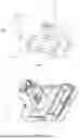
Specifically, the present application is described in detail through the following embodiments. Referring to FIGS. 7 to 9, FIG. 7 is a schematic structural diagram of the first storage posture of the accessory holder; FIG. 8 is a schematic structural diagram of the second storage posture of the accessory holder; and FIG. 9 is a schematic structural diagram showing the details of each storage position of the accessory holder according to some embodiments of the present application.
As shown in FIG. 7, an embodiment of the present application provides an accessory holder 200. The accessory holder 200 includes a storage tray 210 configured to store accessories for a surface cleaning device. The accessories for the surface cleaning device include, for example, a dust collection cylinder, a roller brush, a brush head, etc. The accessory holder 200 further includes a storage rod 220. The storage rod 220 is located on a side of the storage tray 210, extends in a direction substantially perpendicular to the storage tray 210, is configured to store a brush head 300 with an extension rod, and includes a first storage position 221, a second storage position 222 and a third storage position 223. The first storage position 221 and the second storage position 222 cooperate to achieve the first storage posture of the brush head 300, and the first storage position 221 and the third storage position 223 cooperate to achieve the second storage posture of the brush head 300. In the first storage posture, the first storage position 221 engages the extension rod 310, and the second storage position 222 abuts against the adapter portion 320 of the brush head. In the second storage position, the first storage position 221 engages the extension rod 310, and the third storage position 223 abuts against the bottom surface 330 of the brush head. As shown in FIG. 7, the first storage posture is such that the brush head 300 and the extension rod 310 remain perpendicular to each other, and the brush head is placed flat on the ground. As shown in FIG. 8, the second storage posture is such that the brush head 300 and the extension rod 310 are substantially coplanar, and the bottom surface of the brush head is basically perpendicular to the ground. For example, the angle between the brush head 300 and the extension rod 310 may range from 150 degrees to 180 degrees Compared with the first storage combination manner, the second storage combination manner occupies less space and achieves more flexible storage.
In some embodiments, as shown in FIG. 7, the first storage position 221 is located on a side of the second storage position 222 away from the storage tray 210; and the third storage position 223 is located on a side of the second storage position 222 close to the storage tray 210. That is, the first storage position 221, the second storage position 222 and the third storage position 223 are spaced apart in sequence from top to bottom along the storage rod 220, facilitating pairwise cooperation to achieve the two types of storage postures of a roller brush.
In some embodiments, as shown in FIG. 7, the first storage position 221, the second storage position 222 and the third storage position 223 are all located on a side of the storage rod 220 facing away from the storage tray, thereby facilitating the placement of the stored brush head 300 with the extension rod.
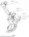
In some embodiments, as shown in FIG. 9, the first storage position 221 extends in a direction substantially perpendicular to the storage rod 220 towards a direction facing away from the storage tray 210, and includes a storage arm 2211 extending in a direction substantially perpendicular to the storage rod 220 towards a direction away from the storage tray 210. A first curved storage structure 2212 is arranged at the tail end of the storage arm 2211, and is configured to store the extension rod 310 of the brush head. The storage arm 2211 is made of a plastic or metal material and has a slightly elastic end, such that the extension rod 310 can be easily snap-fitted into the first curved storage structure 2212. Optionally, an anti-slip structure is arranged on the edge of the inner side of the first curved storage structure 2212 to achieve a more stable snap-fit connection with the extension rod 310 of the brush head.
In some embodiments, as shown in FIG. 9, the second storage position 222 extends in a direction substantially perpendicular to the storage rod 220 towards a direction facing away from the storage tray 210. A second curved storage structure is arranged at the tail end of the second storage position 222, and is configured to store an adapter portion of the brush head. The adapter portion 320 serves to connect the extension rod 310 and the brush head 300, and has a diameter larger than that of the extension rod. When storage is performed by means of the first storage position 221 and the second storage position 222, the first storage position 221 is in snap-fit connection with the extension rod 310, and the second storage position 222 abuts against the adapter portion 320 via the second curved storage structure, enabling the storage of the brush head 300 in the first storage posture. Optionally, the second storage position 222 is composed of a horizontally extending storage plate 2221 and a support plate 2222 supported below the storage plate 2221. A second curved storage structure is arranged at the end of the storage plate 2221.
In some embodiments, as shown in FIG. 9, the third storage position 223 extends in a direction substantially perpendicular to the storage rod 220 towards a direction facing away from the storage tray 210, and a plane where a tail end of the third storage position 223 lies is non-parallel to an axis of the storage rod 220. For example, the plane where the tail end of the third storage position 223 lies is slightly tilted upward to support the bottom surface of the brush head more conveniently, thereby keeping the brush head vertical. For another example, the tail end of the third storage position 223 has a tilted plane that is non-parallel to the axis of the storage rod 220. Optionally, the tilted plane is provided with an anti-slip structure.
In some embodiments, as shown in FIG. 9, the third storage position 223 includes a support cavity 2233 formed by sidewalls 2231 that are substantially perpendicular to the storage rod in a surrounding manner; and reinforcing ribs 2232 are arranged in the support cavity 2233 and serve to connect opposing sidewalls of the cavity. The end surfaces of the sidewalls 2231 form the aforementioned tilted plane, which is non-parallel to the axis of the storage rod 220. This allows the third storage position 223 to support the bottom surface of the brush head at a slightly upwardly tilted angle. Optionally, the end surfaces of the sidewalls 2231 each have an anti-slip structure. The reinforcing ribs 2232 are configured to reinforce the load-carrying capability of the third storage position 223, and the end surfaces of the reinforcing ribs do not extend beyond the plane formed by the end surfaces of the sidewalls 2231. When storage is performed by means of the first storage position 221 and the third storage position 223, the first storage position 221 is in snap-fit connection with the extension rod 310, and the third storage position 223, with its tilted end surface, abuts against the bottom surface 330 that supports the brush head to prevent the bottom surface 330 of the brush head from sliding downward, such that the brush head 300 is stored in the second storage position.
An embodiment of the present application provides a maintenance station system. The maintenance station system includes the main holder as described in the above embodiments and the accessory holder as described in any one of the above embodiments.
The accessory holder provided in the embodiment of the present application has three storage positions, by means of which the user can store the brush head with the extension rod in two manners as needed. In a first storage combination manner, the brush head and the extension rod remain basically perpendicular to each other, and the brush head is placed flat on the ground. In a second storage combination manner, the brush head and the extension rod are substantially coplanar, and the bottom surface of the brush head is substantially perpendicular to the ground. Compared with the first storage combination manner, the second storage combination manner occupies less space and achieves more flexible storage. The present application enables the user to use the two storage manners according to his/her own needs and space environment, thereby improving space utilization and user experience.
A holder (i.e., the main holder as described in the above embodiments) typically includes a plurality of circuit boards or other heat generating components. If a specialized heat dissipation structure is used to dissipate heat for them, both the cost and the overall structure of the holder are increased, adversely affecting the layout of the internal components. Therefore, it is necessary to rationally arrange the holder's internal structure to enhance its heat dissipation performance.
An embodiment of the present application provides a holder (i.e., the main holder as described in the above embodiments) configured to support a surface cleaning device. The holder includes: a housing including an air inlet and an air outlet; a fan disposed in the housing, the fan including an air intake and an air vent; and a component to be cooled, which is disposed in an airflow passage between the air inlet of the housing and the air intake of the fan, such that heat is taken away from the component to be cooled with the flowing of an airflow.
Due to the fan disposed in the holder provided in the embodiment of the present application, an airflow enters via the air intake of the fan and, on its way to the air vent, passes through gaps within the housing. In particular, when flowing through a gap between two main boards, the airflow can conveniently take away heat generated by the two main boards during operation, ensuring an excellent operating environment for the main boards.
Specifically, the present application is described in detail through the following embodiments. Referring to FIGS. 10 to 13, FIG. 10 is a schematic diagram of a cross-sectional structure of the holder according to some embodiments of the present application; FIG. 11 is a schematic diagram of a partially enlarged cross-sectional structure of the holder according to some embodiments of the present application; FIG. 12 is a schematic diagram of a partial back surface structure of the holder according to some embodiments of the present application; and FIG. 13 is a schematic diagram of a partial three-dimensional structure of the holder according to some embodiments of the present application.
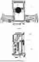
As shown in FIG. 10, an embodiment of the present application provides a holder 100 configured to support and maintain a surface cleaning device, which includes, for example, a handheld floor scrubber, a floor mop, or a vacuum cleaner, etc. The holder 100 includes a tray portion 110, and a support portion 120 that is located on a side of the tray portion 110. The support portion 120 includes a housing 121; the housing 121 includes an air inlet 1211 and an air outlet 1212; the air inlet 1211 is disposed on the back surface of the housing 121; and the air outlet 1212 is disposed on the lower side of the housing 121. The support portion 120 further includes a fan 122 disposed in the housing 121; the fan 122 includes an air intake 1221 and an air vent 1222; and the fan 122 rotates to drive the airflow to flow, allowing the airflow to enter from the air intake 1221 and exit from the air vent 1222. The support portion 120 further includes a component to be cooled 123, which includes a first component to be cooled 1231 (e.g., a first circuit board) and a second component to be cooled 1232 (e.g., a second circuit board). The first component to be cooled 1231 and the second component to be cooled 1232 are provided with a casing to prevent dust or moisture from entering the casing. The component to be cooled 123 is disposed in the airflow passage between the air inlet 1211 of the housing 121 and the air intake 1221 of the fan 122. As the airflow flows, the heat generated by the component to be cooled 123 is taken away from its surface. The airflow passage is shown by the arrows in FIG. 10. In this structure, no additional heat dissipation structure is needed, and the heat is taken away from the component to be cooled 123 directly using the airflow (called the cold airflow before entering the fan) entering the fan, such that the dual purposes of air intake and heat dissipation are achieved.
In some embodiments, as shown in FIG. 11, the airflow passage includes a first gap 1233 between the first component to be cooled 1231 and the second component to be cooled 1232. In some embodiments, the airflow passage includes a second gap 1234 between the surface of the component to be cooled and a rear surface of the housing. In some embodiments, the airflow passage includes two side gaps and/or a bottom gap 1235 of the first component to be cooled. That is, the cold airflow entering from the air intake 1221 can flow through any one or several of the first gap 1233, the second gap 1234, and the two side gaps and bottom gap 1235 of the first component to be cooled 1231. Depending on the fan power, the number of gaps through which the airflow flows also varies. These gaps all surround the first component to be cooled 1231. Therefore, an optimal heat dissipation effect is achieved for the first component to be cooled 1231.
In some embodiments, as shown in FIG. 12, the geometric center of the air inlet 1211 is lower than the lower edge of the first gap 1233. In this embodiment, the air inlet 1211 is circular and thus has a circular geometric center, and if the air inlet is rectangular, its geometric center is the intersection point of its diagonals. Configuring the geometric center of the air inlet 1211 to be lower than the lower edge of the first gap 1233 can ensure that regardless of the size of the air inlet 1211, there is an airflow blowing directly onto the surface of the first component to be cooled 1231, and then the airflow spreads outward in all directions over the surface of the first component to be cooled 1231 and flows along the surface of the first component to be cooled 1231 to any one or more of the first gap 1233, the second gap 1234, and the two side gaps and bottom gap 1235 of the first component to be cooled, thereby ensuring the heat dissipation effect for the first component to be cooled 1231.
In some embodiments, as shown in FIG. 13, the holder 100 further includes a heating component 124, which is, for example, an electric heating wire. The heating component 124 is arranged on the air outlet side of the fan 122. The airflow in the airflow passage exits via the air vent of the fan 122, is then heated by the heating component 124, and subsequently the heated airflow flows out from the air outlet 1212 of the housing. The cold airflow passes through the fan and then enters the heating component 124; after being heated, the cold airflow turns into a hot airflow; and the hot airflow blows to the roller brush through a hot air passage 125 to complete the drying of the roller brush, as shown in FIG. 10. In this embodiment, the front part of the pre-heated airflow for drying in the holder 100 is used as a cooling airflow; the cooling airflow is used to dissipate heat from the component to be cooled before being heated, to fulfill the heat dissipation function; and after passing through the component to be cooled, the cooling airflow is initially heated, and then is heated into a drying airflow through the heating component 124. The airflow of the drying fan is reused for heat dissipation in the cooling process, such that there is no need to provide a heat dissipation fan separately, which is conducive to reducing the power consumption of the heating component 124. In some embodiments, an application scenario shows a higher tolerance for the required drying time and can adapt to a longer drying time. In this case, after the cooling airflow is initially heated by the component to be cooled, a heating component is no longer provided to further heat the cooling air, and the initially heated cooling air is used directly to dry the roller brush. Similarly, the air path of the fan used for other functions in the device can also be reused. For example, the working airflow of a wastewater recovery fan is reused to dissipate heat from the component to be cooled.
Due to the fan disposed in the holder provided in the embodiment of the present application, an airflow enters via the air intake of the fan and, on its way to the air vent, passes through gaps within the housing. In particular, when flowing through a gap between two main boards, the airflow can conveniently take away heat generated by the two main boards during operation, ensuring an excellent operating environment for the main boards.
Finally, it should be noted that the respective embodiments in the Description are described in a progressive manner, each embodiment focuses on the differences from other embodiments, and the same or similar parts between the respective embodiments may be referred to each other.
The above embodiments are only used to illustrate, instead of limiting, the technical solutions of the present application. Although the present application is described in detail with reference to the foregoing embodiments, it can be understood by those of ordinary skill in the art that they can still make modifications to the technical solutions disclosed in the above embodiments or carry out equivalent replacements on some of technical features, and these modifications or replacements do not depart the nature of the corresponding technical solutions from the spirit and scope of the technical solutions of the respective embodiments of the present application.
Claims
1. An accessory holder, comprising:
a storage tray configured to store accessories for a surface cleaning device; and
a storage rod located on a side of the storage tray and configured to store a brush head with an extension rod, the storage rod comprising a first storage position, a second storage position and a third storage position,
wherein the first storage position and the second storage position enable a first storage posture of the brush head, and the first storage position and the third storage position enable a second storage posture of the brush head.
2. The accessory holder according to claim 1, wherein
the first storage position is located on a side of the second storage position away from the storage tray; and the third storage position is located on a side of the second storage position close to the storage tray.
3. The accessory holder according to claim 1, wherein
the first storage position, the second storage position and the third storage position are all located on a side of the storage rod facing away from the storage tray.
4. The accessory holder according to claim 1, wherein
the first storage position extends in a direction substantially perpendicular to the storage rod, a tail end of the first storage position is provided with a first curved storage structure, and the first curved storage structure is configured to store the extension rod of the brush head.
5. The accessory holder according to claim 1, wherein
the second storage position extends in a direction substantially perpendicular to the storage rod, a second curved storage structure is arranged at a tail end of the second storage position, and the second curved storage structure is configured to store an adapter portion of the brush head, wherein the adapter portion has a diameter larger than a diameter of the extension rod.
6. The accessory holder according to claim 1, wherein
the third storage position extends in a direction substantially perpendicular to the storage rod, and a plane where a tail end of the third storage position lies is non-parallel to an axis of the storage rod.
7. The accessory holder according to claim 1, wherein
a plane where a tail end of the third storage position lies is tilted upward relative to an axis of the storage rod.
8. The accessory holder according to claim 1, wherein the third storage position comprises:
a support cavity, formed by sidewalls substantially perpendicular to the storage rod in a surrounding manner; and
reinforcing ribs connecting opposing sidewalls of the cavity.
9. The accessory holder according to claim 1, wherein the first storage posture is such that the brush head is substantially perpendicular to the extension rod, and the second storage posture is such that the brush head and the extension rod are substantially coplanar.
10. The accessory holder according to claim 1, wherein in the first storage posture, the first storage position engages the extension rod, and the second storage position abuts against an adapter portion of the brush head; and in the second storage posture, the first storage position engages the extension rod, and the third storage position abuts against a bottom surface of the brush head.
11. A maintenance station system, comprising an accessory holder, wherein the accessory holder comprises:
a storage tray configured to store accessories for a surface cleaning device; and
a storage rod located on a side of the storage tray and configured to store a brush head with an extension rod, the storage rod comprising a first storage position, a second storage position and a third storage position,
wherein the first storage position and the second storage position enable a first storage posture of the brush head, and the first storage position and the third storage position enable a second storage posture of the brush head.
12. The maintenance station system according to claim 11, wherein
the first storage position is located on a side of the second storage position away from the storage tray; and the third storage position is located on a side of the second storage position close to the storage tray.
13. The maintenance station system according to claim 11, wherein
the first storage position, the second storage position and the third storage position are all located on a side of the storage rod facing away from the storage tray.
14. The maintenance station system according to claim 11, wherein
the first storage position extends in a direction substantially perpendicular to the storage rod, a tail end of the first storage position is provided with a first curved storage structure, and the first curved storage structure is configured to store the extension rod of the brush head.
15. The maintenance station system according to claim 11, wherein
the second storage position extends in a direction substantially perpendicular to the storage rod, a second curved storage structure is arranged at a tail end of the second storage position, and the second curved storage structure is configured to store an adapter portion of the brush head, wherein the adapter portion has a diameter larger than a diameter of the extension rod.
16. The maintenance station system according to claim 11, wherein
the third storage position extends in a direction substantially perpendicular to the storage rod, and a plane where a tail end of the third storage position lies is non-parallel to an axis of the storage rod.
17. The maintenance station system according to claim 11, wherein
a plane where a tail end of the third storage position lies is tilted upward relative to an axis of the storage rod.
18. The maintenance station system according to claim 11, wherein the third storage position comprises:
a support cavity, formed by sidewalls substantially perpendicular to the storage rod in a surrounding manner; and
reinforcing ribs connecting opposing sidewalls of the cavity.
19. The maintenance station system according to claim 11, wherein the first storage posture is such that the brush head is substantially perpendicular to the extension rod, and the second storage posture is such that the brush head and the extension rod are substantially coplanar.
20. The maintenance station system according to claim 11, wherein in the first storage posture, the first storage position engages the extension rod, and the second storage position abuts against an adapter portion of the brush head; and in the second storage posture, the first storage position engages the extension rod, and the third storage position abuts against a bottom surface of the brush head.
Images & Drawings included:


Sources:
- United States Patent and Trademark Office - verify current appl. status at the USPTO↗
Recent applications in this class:
- » 20260053326 2026-02-26
SELF-CLEANING METHOD OF CLEANING SYSTEM - » 20260053325 2026-02-26
DOCKING STATION FOR A CLEANING ROBOT AND CLEANING SYSTEM - » 20260033696 2026-02-05
ROBOT CLEANING SYSTEM, BASE STATION, AND CONTROL METHOD - » 20250386997 2025-12-25
STATION AND CLEANING SYSTEM - » 20250380848 2025-12-18
PILE, CLEANING APPARATUS AND CLEANING SYSTEM - » 20250375083 2025-12-11
Self-Cleaning Method of Cleaning System - » 20250302268 2025-10-02
CLEANING SYSTEM AND METHOD FOR CONTROLLING THE SAME - » 20250302267 2025-10-02
CHARGING AND REFUELLING STATION FOR AUTONOMOUS CLEANING ROBOTS - » 20250295285 2025-09-25
STATION AND CLEANING DEVICE - » 20250275662 2025-09-04
BASE STATION AND CLEANING ROBOT SYSTEM