ATOMIZATION ASSEMBLY AND ELECTRONIC ATOMIZATION DEVICE
US20260076407A1
2026-03-19
19/332,503
2025-09-18
Smart Summary: An atomization assembly is designed to hold a liquid that can be turned into a mist. It has a liquid storage area with an opening at the bottom for the liquid to flow out. There are also vent channels that connect the liquid storage to the outside air, helping with the atomization process. A special blocking piece is placed in the storage area to prevent air bubbles from moving back into the liquid opening. This design helps ensure a smooth and effective atomization of the liquid. 🚀 TL;DR
Abstract:
An atomization assembly and an electronic atomization device are provided. The atomization assembly includes a liquid storage cavity is configured to store an atomizing medium. A liquid opening is communicated with a bottom portion of the liquid storage cavity. At least one vent channel includes a first port and a second port. The first port is in communication with the liquid storage cavity, and the second port is in communication with an outside atmosphere. A blocking member is arranged in the liquid storage cavity and located on a side of the second port facing the liquid feeding opening. The blocking member minimizing air bubbles flowing from the second port to the liquid opening.
Inventors:
- Ju XIE 15 🇨🇳 Shenzhen, China
- Haiyan QU 3 🇨🇳 Shenzhen, China
- Qike LAN 3 🇨🇳 Shenzhen, China
- Xiaojun ZHONG 6 🇨🇳 Shenzhen, China
- Zhixiao LUO 3 🇨🇳 Shenzhen, China
Assignee:
- Verdewell International Holdings Limited 2 Grand Cayman, Cayman Islands
Applicant:
Interested in similar patents?
Get notified when new applications in this technology area are published.
Classification:
A24F40/10 » CPC main
Electrically operated smoking devices; Component parts thereof; Manufacture thereof; Maintenance or testing thereof; Charging means specially adapted therefor Devices using liquid inhalable precursors
A24F40/48 » CPC further
Electrically operated smoking devices; Component parts thereof; Manufacture thereof; Maintenance or testing thereof; Charging means specially adapted therefor; Constructional details, e.g. connection of cartridges and battery parts Fluid transfer means, e.g. pumps
Description
RELATED APPLICATION
The present application claims priority of a Chinese Patent Application No. 202411312760.6, filed on Sep. 19, 2024. The entire disclosure of the prior application is hereby incorporated by reference.
TECHNICAL FIELD
This present disclosure relates to the field of aerosol generating technologies, including to an atomization assembly and an electronic atomization device.
BACKGROUND
An electronic atomization device is a device that can heat and atomize an atomizing medium to form an aerosol after being powered on. The electronic atomization device generally includes a suction nozzle, an atomization assembly, and a power supply component. The power supply component is configured to supply power to the atomization assembly. The atomization assembly is configured to heat and atomize the atomizing medium to form an aerosol after being powered on. The suction nozzle is in communication with the atomization assembly and is configured to discharge the aerosol. To prevent liquid feeding difficulty in the atomizing medium of a liquid storage cavity and prevent liquid leakage caused by imbalance of pressures in the liquid storage cavity, a vent channel is generally arranged. The vent channel is configured to enable the liquid storage cavity to be in communication with an outside atmosphere. However, during ventilation, the air entering the liquid storage cavity through the vent channel may form bubble in the atomizing medium, and the bubble may block a liquid feeding opening of the liquid storage cavity, causing the liquid feeding difficulty, and finally causing a case of dry heating of the atomization assembly.
SUMMARY
This disclosure is to provide an atomization assembly and an electronic atomization device, to solve a technical problem of liquid feeding difficulty in an atomizing medium of a liquid storage cavity in the prior art.
To achieve the foregoing objective, this disclosure adopts the following technical solutions. An atomization assembly is provided. The atomization assembly includes:
-
- a liquid storage cavity, configured to store an atomizing medium; a liquid opening, in communication with a bottom portion of the liquid storage cavity;
- at least one vent channel, having a first port and a second port, where the first port is in communication with the liquid storage cavity, and the second port is in communication with an outside atmosphere; and
- a blocking member, arranged in the liquid storage cavity and located on a side of the second port facing the liquid feeding opening, to minimize air bubbles flowing from the second port to the liquid opening.
In an aspect, the second port, the blocking member, and the liquid feeding opening are distributed in sequence along a first direction; and
-
- a first projection of the blocking member covers a second projection of the second port along the first direction. In an aspect, two opposite ends of the blocking member along a second direction respectively extend at least 0.5 mm relative to two opposite ends of the second port along the second direction; and
- every two of the second direction, the first direction, and a longitudinal direction of the atomization assembly are perpendicular to each other.
In an aspect, the blocking member is at least 0.5 mm higher than the second port along a longitudinal direction of the atomization assembly.
In an aspect, the blocking member is integrally formed on an inner wall of the liquid storage cavity; or
-
- the blocking member is fixedly connected to the inner wall of the liquid storage cavity.
In an aspect, one or more vent channels are provided; and when a plurality of vent channels is provided, the second ports of the vent channels are evenly distributed around the liquid feeding opening.
In an aspect, the atomization assembly includes: a liquid storage tank, having the liquid storage cavity and the liquid feeding opening;
-
- an atomization base, connected to the liquid storage tank to jointly form an atomization cavity;
- a heating element, in liquid communication with the liquid storage cavity and in gas communication with the atomization cavity; and
- a seal gasket, abutting between the heating element and the liquid storage tank/the atomization base, where
- the vent channel is formed in the liquid storage tank; or the vent channel is formed through the liquid storage tank and the seal gasket.
In an aspect, the atomization assembly further includes an atomization cavity, where the second port of the vent channel is in communication with the atomization cavity. A capillary channel is provided in the atomization cavity, the capillary channel is in communication with a bottom portion of the atomization cavity, and a top end of the capillary channel is in direct communication or in communication with the second port of the vent channel through a gap.
In an aspect, the atomization assembly further includes a heating element, where the top end of the capillary channel is arranged close to the heating element.
In an aspect, an electrode electrically connected to the heating element is arranged in the atomization cavity, and the electrode is mounted to one of side walls of the capillary channel.
In an aspect, the atomization assembly includes an atomization base, where the atomization base includes a bottom plate, a surrounding bone, and a supporting bone. The surrounding bone protrudes from a peripheral edge of the bottom plate, and the bottom plate and the surrounding bone define the atomization cavity. The supporting bone protrudes from the bottom plate, the supporting bone is spaced apart from the surrounding bone to form the capillary channel, and the electrode is supported by the supporting bone.
According to another aspect, this disclosure further provides an electronic atomization device, including a suction nozzle, a power supply component, and an atomization assembly. The suction nozzle is in communication with the atomization assembly. The power supply component is configured to supply power to the atomization assembly.
The beneficial effects of the atomization assembly and electronic atomization device provided in this disclosure are as follows. The blocking member is arranged in the liquid storage cavity, and the blocking member is arranged on a side of the second port facing the liquid feeding opening, to block the bubble flowing from the second port to the liquid feeding opening, so that the second port does not flow toward the liquid feeding opening on a front side. In other words, the air entering the liquid storage cavity from the second port does not flow toward the liquid feeding opening on a front side, but are blocked through the blocking member, and then slowly floats up to a liquid surface, or even disappears. Therefore, the bubble is prevented from flowing to the liquid feeding opening and blocking the liquid feeding opening, thereby ensuring smooth liquid feeding and preventing a case of dry heating of the atomization assembly.
BRIEF DESCRIPTION OF THE DRAWINGS
To describe technical solutions in this disclosure more clearly, drawings required for describing the examples are briefly described below. The drawings in the following description show only some aspects of this disclosure, and a person of ordinary skill in the art can derive other drawings from the drawings without creative efforts.
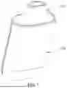
FIG. 1 is a schematic three-dimensional structural view of an electronic atomization device according to an aspect of this disclosure.
FIG. 2 is a schematic cross-sectional view of an electronic atomization device along a front-rear direction according to an aspect of this disclosure.
FIG. 3 is a partial enlarged schematic structural diagram of A in FIG. 2.
FIG. 4 is a schematic structural top view of a liquid storage tank in an electronic atomization device according to an aspect of this disclosure.
FIG. 5 is a partial schematic cross-sectional view of an atomization assembly corresponding to a vent channel according to an aspect of this disclosure.
FIG. 6 is a schematic structural diagram of a bottom side of an atomization assembly according to an aspect of this disclosure.
FIG. 7 is a schematic structural diagram of a top side of an atomization assembly according to an aspect of this disclosure.
FIG. 8 is a schematic cross-sectional view of an electronic atomization device corresponding to a heating element and two electrodes along a left-right direction according to an aspect of this disclosure.
FIG. 9 is a partial schematic diagram of an atomization base in an electronic atomization device according to an aspect of this disclosure.
FIG. 10 is a schematic structural diagram of two electrodes in an electronic atomization device according to an aspect of this disclosure.
FIG. 11 is a schematic cross-sectional view of an electronic atomization device corresponding to a heating element and two electrodes along a left-right direction according to another aspect of this disclosure.
FIG. 12 is a schematic cross-sectional view of an electronic atomization device corresponding to a start airway along a left-right direction according to an aspect of this disclosure.
REFERENCE NUMERALS IN THE DRAWINGS
100. Atomization assembly; 110. Liquid storage tank; 111. Liquid storage cavity; 112.
Liquid feeding opening; 113. Blocking member; 114. Mounting groove; 115. Main airway; 116. Start airway; 117. Arc-shaped guide surface; 119. Insertion portion; 120. Atomization base; 121. Bottom plate; 1211. Insertion hole; 1212. Insertion slot; 1213. Connection hole; 122. Surrounding bone; 1221. E-liquid storage groove; 1222. Capillary groove; 123. Supporting bone; 124. Capillary channel; 125. Connection rib; 126. Connection groove; 127. Air inlet post; 1271. Air inlet channel; 128. Air inlet hole; 130. Heating element; 140. Seal gasket; 150. Electrode; 150a. First electrode; 150b. Second electrode; 151. First fitting section; 152. Second fitting section; 153. Bent portion; 154. Insertion section; 160. Atomization cavity; 170. Vent channel; 171. First channel; 1711. First port; 1712. Third port; 172. Second channel; 1721. Second port; 1722. Fourth port; 1723. First longitudinal hole; 1724. Second longitudinal hole; 1725. Transverse hole; 200. Suction nozzle; 210. Air cavity; 220. Air outlet; 300. Power supply component; 310. Battery; 320. Control board; 340. Seal sleeve; 342. Negative pressure groove; 400. Main housing; 500. Bottom housing; 600. Suction nozzle seal member; X. First direction; Y. Second direction.
DETAILED DESCRIPTION
To make technical problems to be solved in this disclosure, technical solutions, and beneficial effects more comprehensible, this disclosure is described below in further detail with reference to drawings and aspects. It should be understood that specific aspects described herein are merely used for explaining this disclosure but are not intended to limit this disclosure.
It should be noted that when an element is referred to as “being fixed to” or “being arranged on” another element, the element may be directly located on another element or indirectly on another element. When an element is referred to as “being connected to” another element, the element may be directly connected to another element or indirectly connected to another element.
It should be understood that orientation or position relationships indicated by the terms such as “length”, “width”, “up”, “down”, “front”, “back”, “left”, “right”, “vertical”, “horizontal”, “top”, “bottom”, “inside”, and “outside” are based on orientation or position relationships shown in the drawings, and are used only for ease and brevity of illustration and description, rather than indicating or implying that the mentioned apparatus or element must have a particular orientation or must be constructed and operated in a particular orientation. Therefore, the terms should not be construed as a limitation on this disclosure.
In addition, terms “first” and “second” are merely used for description, and cannot be understood as indicating or implying relative importance or implying a quantity of indicated technical features. Therefore, a feature defined with “first” or “second” may explicitly or implicitly include one or more features. In the descriptions of this disclosure, “a plurality of” means two or more, unless otherwise definitely and specifically limited.
As stated in the background, to prevent liquid feeding difficulty in an atomizing medium of a liquid storage cavity of an atomization assembly and prevent liquid leakage caused by imbalance of pressures in the liquid storage cavity, a vent channel is generally arranged. The vent channel is configured to enable the liquid storage cavity to be in communication with an outside atmosphere. The vent channel allows air inside the liquid storage cavity to exchange with the external environment, to help maintain pressure balance between the pressure inside the liquid storage cavity and the external environment. However, during ventilation, the air entering the liquid storage cavity through the vent channel may form a bubble in the atomizing medium, and the bubble may block a liquid feeding opening of the liquid storage cavity, causing liquid feeding difficulty, and finally causing a case of dry heating of the atomization assembly.
To resolve the foregoing problem, this disclosure provides an atomization assembly 100 and an aerosol generating device. A blocking member 113 is arranged between a vent channel 170 and a liquid feeding opening 112, and the bubble flowing to the liquid storage cavity 111 through the vent channel 170 is blocked by using the blocking member 113, to block the bubble from entering the liquid feeding opening 112 and block the liquid feeding opening 112, to ensure smooth liquid feeding of the liquid storage cavity 111, thereby preventing a case of dry heating of the atomization assembly 100.
Referring to FIG. 1 and FIG. 2, an aspect of this disclosure provides an electronic atomization device, including an atomization assembly 100, a suction nozzle 200, and a power supply component 300. The power supply component 300 is configured to supply power to the atomization assembly 100. The atomization assembly 100 stores an atomizing medium, and the atomization assembly 100 can heat and atomize the atomizing medium to form an aerosol after being powered on. The suction nozzle 200 is in communication with the atomization assembly 100, and the suction nozzle 200 is configured to allow the aerosol generated by the atomization assembly 100 to flow out for a user to inhale.
Referring to FIG. 2 to FIG. 4, the atomization assembly 100 in the aspects of this disclosure is now be described.
The atomization assembly 100 has a liquid storage cavity 111, a liquid feeding opening 112, a vent channel 170, and a blocking member 113. The liquid storage cavity 111 is configured to store an atomizing medium. The liquid feeding opening 112 is in communication with a bottom portion of the liquid storage cavity 111. The vent channel 170 has a first port 1711 and a second port 1721, the first port 1711 is in communication with the liquid storage cavity 111, and the second port 1721 is in communication with an outside atmosphere. The blocking member 113 is arranged in the liquid storage cavity 111, and the blocking member 113 is located on a side of the second port 1721 facing the liquid feeding opening 112, to block a bubble flowing from the second port 1721 to the liquid feeding opening 112.
That the liquid feeding opening 112 is in communication with a bottom portion of the liquid storage cavity 111 means that the liquid feeding opening 112 extends outward from the bottom portion of the liquid storage cavity 111, and the liquid feeding opening 112 is in communication with the liquid storage cavity 111, so that the atomizing medium in the liquid storage cavity 111 can flow to the heating element 130 through the liquid feeding opening 112.
The first port 1711 of the vent channel 170 is in communication with the liquid storage cavity 111, the second port 1721 of the vent channel 170 is in communication with the outside atmosphere, and the vent channel 170 extends from the first port 1711 to the second port 1721.
The first port 1711 of the vent channel 170 may be located at a bottom side wall or a peripheral side wall of the liquid storage cavity 111. The second port 1721 of the vent channel 170 may be directly in communication with the outside atmosphere. The second port 1721 of the vent channel 170 may further be in communication with the outside atmosphere through the atomization cavity 160.
That the blocking member 113 is arranged on a side of the second port 1721 facing the liquid feeding opening 112 means that the blocking member 113 is arranged on a side of the second port 1721 facing the liquid feeding opening 112, and the blocking member 113 and the second port 1721 are arranged at intervals. The blocking member 113 blocks the second port 1721, so that the second port 1721 does not face toward the liquid feeding opening 112. In other words, a bubble generated when entering the liquid storage cavity 111 from the second port 1721 do not flow toward the liquid feeding opening 112 on a front side, but are blocked by the blocking member 113, and then slowly float up and disappear.
In the atomization assembly 100 in this aspect of this disclosure, the blocking member 113 is arranged in the liquid storage cavity 111, and the blocking member 113 is arranged on a side of the second port 1721 facing the liquid feeding opening 112, to block the bubble flowing from the second port 1721 to the liquid feeding opening 112, so that the second port 1721 does not flow toward the liquid feeding opening 112 on a front side. In other words, the bubble generated when entering the liquid storage cavity 111 from the second port 1721 does not flow toward the liquid feeding opening 112 on a front side, but is blocked by the blocking member 113, and then slowly floats up to a liquid surface, or even disappears. Therefore, the bubble is prevented from flowing to the liquid feeding opening 112 and blocking the liquid feeding opening 112, thereby ensuring smooth liquid feeding and preventing a case of dry heating of the atomization assembly 100.
In an aspect, referring to FIG. 4, the second port 1721, the blocking member 113, and the liquid feeding opening 112 are distributed in sequence along a first direction X; and a first projection of the blocking member 113 covers a second projection of the second port 1721 along the first direction X.
The first direction X may be a front-rear direction of the atomization assembly 100, a left-right direction of the atomization assembly 100, or even a direction forming an included angle with the front-rear direction of the atomization assembly 100. This aspect is described by using an example in which the first direction X is the left-right direction of the atomization assembly 100.
That the second port 1721, the blocking member 113, and the liquid feeding opening 112 are distributed in sequence along the first direction X means that the blocking member 113 is arranged at a position in which the second port 1721 and the liquid feeding opening 112 are distributed. In other words, the blocking member 113 is arranged at a side from the second port 1721 to the liquid feeding opening 112, to effectively block the bubble formed by the air entering the liquid storage cavity 111 through the second port 1721.
A shape of the second projection of the second port 1721 along the first direction X may vary based on a forming position of the second port 1721. For example, when a bottom surface of the liquid storage cavity 111 is a plane, the second projection of the second port 1721 in the first direction X is a line. For another example, when a bottom surface of the liquid storage cavity 111 is a surface inclined to a direction of the liquid feeding opening 112, the second projection of the second port 1721 along the first direction X is oval or oblate. However, no matter the bottom surface of the liquid storage cavity 111 is a plane or an inclined surface, the first projection of the blocking member 113 along the first direction X can cover the second projection of the second port 1721. In other words, the blocking member 113 can completely block the second port 1721, to effectively block the bubble formed by the air entering the liquid storage cavity 111 through the second port 1721.
In this disclosure, the bubble has certain fluidity. Therefore, to prevent the bubble from bypassing the blocking member 113 and flowing to the liquid feeding opening 112, in an aspect, referring to FIG. 4, two opposite ends of the blocking member 113 along a second direction Y respectively extend at least 0.5 mm relative to two opposite ends of the second port 1721 along the second direction Y; and every two of the second direction Y, the first direction X, and a longitudinal direction of the atomization assembly 100 are perpendicular to each other.
The longitudinal direction of the atomization assembly 100 refers to an extension direction of a main airway 115 of the atomization assembly 100, namely, a height direction of the atomization assembly 100 when the atomization assembly is vertically placed. The first direction X and the second direction Y are both perpendicular to the longitudinal direction of the atomization assembly 100. Therefore, the first direction X and the second direction Y are both a transverse direction of the atomization assembly 100. When the first direction X is the left-right direction, the second direction Y is the front-rear direction; and when the first direction X is the front-rear direction, the second direction Y is the left-right direction.
Referring to FIG. 4, it is assumed that a distance between one end of the blocking member 113 along the second direction Y and a corresponding end of the second port 1721 along the second direction Y is set to d1 and a distance between another end of the blocking member 113 along the second direction Y and a corresponding end of the second port 1721 along the second direction Y is set to d2, d1 is greater than or equal to 0.5 mm, and d2 is greater than or equal to 0.5 mm. Specifically, dimensions of d1 and d2 may be 0.5 mm, 0.6 mm, 0.7 mm, 0.8 mm, 0.9 mm, 1.0 mm, 1.1 mm, 1.2 mm, and 1.3 mm, or even more, provided that the design of the blocking member 113 does not affect the liquid fluidity. Through such setting, the blocking member 113 can shield the bubble entering from the second port 1721 within a specific range along the second direction Y, and prevent the bubble from bypassing the blocking member 113 along the second direction Y and flowing to the liquid feeding opening 112.
In this disclosure, a position relationship between the second port 1721 and the liquid feeding opening 112 may be set according to an actual situation. The second port 1721 may be located on any side of the liquid feeding opening 112. For example, the second port 1721 may be provided in front of, behind, on the left of, or on the right of the liquid feeding opening 112. In addition, the second port 1721 may be located at a central position of the liquid feeding opening 112 along the second direction Y, and the second port 1721 may further be located at a position close to an edge of the liquid feeding opening 112 along the second direction Y.
In an example, referring to FIG. 4, the second port 1721 is located at a position of the liquid feeding opening 112 close to the edge along the second direction Y, and a dimension of the liquid feeding opening 112 along the second direction Y is much greater than a dimension of the second port 1721 along the second direction Y. In this case, d2 may be set to be greater than d1, so that the blocking member 113 can effectively block the bubble. In addition, the dimension of d1 is set to be relatively small, to reduce the dimension of the entire blocking member 113 in the second direction Y, and reduce impact caused by the blocking member 113 on the liquid flow.
In another example, the second port 1721 is located at a position close to a center of the liquid feeding opening 112 along the second direction Y. In this case, a central plane of the blocking member 113 along the second direction Y may overlap a central plane of the second port 1721 along the second direction Y. In other words, dimensions of extending relative to two opposite ends of the blocking member 113 along the second direction Y relative to two opposite ends of the second port 1721 along the second direction Y are the same.
In an aspect, referring to FIG. 4, the liquid feeding opening 112 has a rectangular cross section, so that the atomizing medium in each orientation in the liquid storage cavity 111 can evenly flow to the liquid feeding opening 112 for liquid feeding. It may be understood that, in another aspect of this disclosure, the cross section of the liquid feeding opening 112 may alternatively be square, circular, oval, or another combined shape. The combined shape refers to a closed shape formed by sequentially connecting a straight line and/or a curve head to tail.
In an aspect, referring to FIG. 4, a cross section of the second port 1721 is circular, so that the air can enter the liquid storage cavity 111 at a constant velocity. It may be understood that, in another aspect of this disclosure, the cross section of the second port 1721 may alternatively be square, oval, or another combined shape. The combined shape refers to a closed shape formed by sequentially connecting a straight line and/or a curve head to tail.
In this disclosure, one or more vent channels 170 may be provided. When a plurality of vent channels 170 are provided, the second ports 1721 of the vent channels 170 are evenly distributed around the liquid feeding opening 112. In this way, vent effects of the vent channels 170 may be evenly distributed.
In an example, referring to FIG. 4, two vent channels 170 are provided, second ports 1721 of the two vent channels 170 are located at two diagonal positions of the liquid feeding opening 112, and the second ports 1721 of the two vent channels 170 are symmetrically arranged relative to a center line of the liquid feeding opening 112. In another aspect, three, four, or more vent channels 170 may be provided.
In an aspect, the blocking member 113 is at least 0.5 mm higher than the second port along a longitudinal direction of the atomization assembly 100. Specifically, the blocking member 113 may be higher than the second port by 0.5 mm, 0.6 mm, 0.7 mm, 0.8 mm, 0.9 mm, 1.0 mm, 1.1 mm, 1.2 mm, 1.3 mm, 1.4 mm, 1.5 mm, or 1.6 mm. Theoretically, a higher height of the blocking member 113 is better. Certainly, processing difficulty of the blocking member 113 also needs to be considered. Therefore, the height of the blocking member 113 preferably does not need to be higher than 3.0 mm.
In an aspect, referring to FIG. 3, the blocking member 113 is integrally formed on an inner wall of the liquid storage cavity 111. In other words, the blocking member 113 is integrally connected to the liquid storage tank 110 formed in the liquid storage cavity 111. The blocking member 113 is integrally formed with the liquid storage tank 110, which not only reduces a processing process of the blocking member 113, but also reduces an assembly process of the blocking member 113, thereby ensuring a blocking effect of the blocking member 113. It may be understood that, in another aspect of this disclosure, the blocking member 113 may also be fixedly connected to the inner wall of the liquid storage cavity 111. Specifically, the blocking member 113 is independently processed and arranged, and then the blocking member 113 is fixedly connected to the inner wall of the liquid storage cavity 111 in a manner such as interference fitting, adhesive bonding, screwing and locking, or secondary injection molding.
In an aspect, the blocking member 113 has a long flat shaped structure. The dimension of the blocking member 113 along the second direction Y is much greater than the dimension of the blocking member 113 along the first direction X. Through such setting, a blocking capability of the blocking member 113 along the second direction Y is sufficiently large, and a volume of the blocking member 113 in the liquid storage cavity 111 is as small as possible.
In an aspect, referring to FIG. 4, the atomization assembly 100 includes a liquid storage tank 110, an atomization base 120, a heating element 130, and a seal gasket 140. The liquid storage cavity 111 and the liquid feeding opening 112 are both formed in the liquid storage tank 110. The atomization base 120 is connected to the liquid storage tank 110 to jointly form an atomization cavity 160. The heating element 130 is in liquid communication with the liquid storage cavity 111, and the heating element 130 is in gas communication with the atomization cavity 160. The seal gasket 140 abuts between the heating element 130 and the liquid storage tank 110/the atomization base 120. The vent channel 170 is formed in the liquid storage tank 110; or the vent channel 170 is formed through the liquid storage tank 110 and the seal gasket 140.
That the vent channel 170 is formed in the liquid storage tank 110 and the seal gasket 140 means that the vent channel 170 respectively passes through the liquid storage tank 110 and the seal gasket 140, so as to form the liquid storage cavity 111 that is in communication with the outside atmosphere. The vent channel 170 may sequentially pass through the liquid storage tank 110 and the seal gasket 140 until being in communication with the atomization cavity 160, so as to form the liquid storage cavity 111 that is in communication with the outside atmosphere. Alternatively, the vent channel 170 may sequentially pass through the liquid storage tank 110, the seal gasket 140, and the liquid storage tank 110 until being in communication with the outside atmosphere, so as to form the liquid storage cavity 111 that is in communication with the outside atmosphere. The vent channel 170 passes through the seal gasket 140, and the seal gasket 140 is close to the heating element 130 herein. Therefore, heat generated by the heating element 130 can be conducted to the vent channel 170, to heat the air in the vent channel 170, thereby promoting ventilation.
That the vent channel 170 is formed in the liquid storage tank 110 means that the liquid storage cavity 111 that is in communication with the outside atmosphere may be formed by directly arranging the vent channel 170 on a side wall of the liquid storage tank 110.
In an aspect, referring to FIG. 3, the liquid storage tank 110 further has a mounting groove 114. The mounting groove 114 is located on a side of the liquid feeding opening 112 facing away from the liquid storage cavity 111. The mounting groove 114 is in communication with the liquid feeding opening 112. The heating element 130 is accommodated in the mounting groove 114. The seal gasket 140 is mounted to the mounting groove 114, and the seal gasket 140 is abutted between an outer wall of the heating element 130 and an inner wall of the mounting groove 114.
In an aspect, referring to FIG. 5 to FIG. 7, the vent channel 170 includes a first channel 171 and a second channel 172. The first channel 171 is formed in the liquid storage tank 110, and the second channel 172 is formed in the seal gasket 140. The first channel 171 has a first port 1711 and a third port 1712. The second channel 172 has a second port 1721 and a fourth port 1722. The third port 1712 and the fourth port 1722 are arranged in relative communication. The vent channel 170 extends from the first port 1711 to the third port 1712, and extends from the fourth port 1722 to the second port 1721.
In an aspect, referring to FIG. 6, the second channel 172 includes a first longitudinal hole 1723, a second longitudinal hole 1724, and a transverse hole 1725. The transverse hole 1725 extends along a peripheral direction of the seal gasket 140. The first longitudinal hole 1723 is in communication with one end of the transverse hole 1725. The first longitudinal hole 1723 extends from the transverse hole 1725 to the fourth port 1722 along the longitudinal direction. The second longitudinal hole 1724 is in communication with another end of the transverse hole 1725. The second longitudinal hole 1724 extends from the transverse hole 1725 to the second port 1721 along the longitudinal direction. The arrangement of the first longitudinal hole 1723 enables the air to quickly enter the third port 1712 through the fourth port 1722. The arrangement of the second longitudinal hole 1724 enables the air or the liquid in the atomization cavity 160 to quickly enter the second longitudinal hole 1724. The arrangement of the transverse hole 1725 can increase a length of the entire second channel 172, and can lock more liquid, thereby reducing a risk of liquid leakage from the liquid storage cavity 111.
In this disclosure, a length of the transverse hole 1725 is set based on the quantity of the vent channels 170. When one vent channel 170 is provided, the transverse hole 1725 may cover four side edges of the seal gasket 140. When two vent channels 170 are provided, the transverse hole 1725 may cover two adjacent side edges of the seal gasket 140. In addition, a long side or a short side may be selected based on a length requirement.
In an aspect, reference is made. The atomization assembly 100 further has an atomization cavity 160, and the second port 1721 of the vent channel 170 is in communication with the atomization cavity 160. A capillary channel 124 is provided in the atomization cavity 160, and a top end of the capillary channel 124 is in direct communication or in communication with the second port 1721 of the vent channel 170 through a gap.
It should be noted that the capillary channel 124 herein means that at least one dimension of the first cross section perpendicular to a length extension direction of the capillary channel 124 is relatively small, so that a liquid can flow upward along the capillary channel 124 under a capillary action. The first cross section of the capillary channel 124 may be rectangular, square, circular, oval, or another combined shape.
In addition, it should be noted that, that the top end of the capillary channel 124 is in direct communication with the second port 1721 of the vent channel 170 means that liquid flowing out from the top end of the capillary channel 124 may directly enter the second port 1721 of the vent channel 170. That the top end of the capillary channel 124 is in communication with the second port 1721 of the vent channel 170 through a gap means that a gap is defined between the top end of the capillary channel 124 and the second port 1721 of the vent channel 170, but the gap is relatively small, so that the liquid in the capillary channel 124 may enter the vent channel 170 under the capillary action. Specifically, the gap may be set to be less than 2 mm.
After the atomization assembly 100 is used for a period of time or placed for a period of time, a certain volume of liquid accumulates at a bottom portion of the atomization cavity 160. In this aspect, the capillary channel 124 is arranged in the atomization cavity 160, and the top end of the capillary channel 124 is in direct communication or in communication with the second port 1721 of the vent channel 170 through a gap, so that when air pressure changes in the liquid storage cavity 111 and needs to be exchanged, an accumulated liquid can climb upward along the capillary channel 124 to the second port 1721 of the vent channel 170 under the capillary action, and flow back into the liquid storage cavity 111 through the vent channel 170 under pushing of exchange air pressure, so that the accumulated liquid can be repeatedly used, thereby improving a utilization rate of the atomizing medium. In addition, it can be prevented that an air inlet channel 1271 is blocked due to excessive liquid accumulation.
In an aspect, referring to FIG. 9, the bottom portion of the capillary channel 124 is in communication with the bottom portion of the atomization cavity 160. Through such arrangement, when the liquid storage cavity 111 is vented, a liquid accumulated at the bottom portion of the atomization cavity 160 is drawn into the capillary channel 124 from a side surface of the capillary channel 124 under the capillary action, and climbs upward along the capillary channel 124 to the second port 1721 of the vent channel 170, to prevent the liquid accumulated at the bottom portion of the atomization cavity 160, and prevent the liquid accumulated at the bottom portion of the atomization cavity 160 from entering the air inlet channel 1271 to block the air inlet channel 1271. Specifically, referring to FIG. 9, the capillary channel 124 has two openings arranged opposite to each other. The two openings are in communication with the atomization cavity 160, and the accumulated liquid in the atomization cavity 160 can be drawn into the capillary channel 124 through the two openings.
In an aspect, referring to FIG. 8, the atomization assembly 100 further includes a heating element 130, and the top end of the capillary channel 124 is arranged close to the heating element 130. Through such arrangement, the heat generated by the heating element 130 can be transferred to the capillary channel 124, to promote the fluidity of the liquid in the capillary channel 124, thereby providing a liquid back-drawing effect.
In an aspect, referring to FIG. 8, an electrode 150 electrically connected to the heating element 130 is arranged in the atomization cavity 160, and the electrode 150 is mounted to one of the side walls of the capillary channel 124. In this aspect, the electrode 150 is mounted to one of the side walls of the capillary channel 124, so that heat generated when the electrode 150 is powered on can be transferred to the capillary channel 124, to heat a liquid in the capillary channel 124, improve a flow characteristic of the liquid, and promote accumulated liquid recovery. Certainly, in another aspect, according to an actual design situation, the electrode 150 may not be arranged on one of the side walls of the capillary channel 124, which is not uniquely limited herein.
In an aspect, referring to FIG. 8, the atomization assembly 100 includes an atomization base 120. The atomization base 120 includes a bottom plate 121, a surrounding bone 122, and a supporting bone 123. The surrounding bone 122 protrudes from a peripheral edge of the bottom plate 121, and the bottom plate 121 and the surrounding bone 122 define the atomization cavity 160. The supporting bone 123 protrudes from the bottom plate 121, the supporting bone 123 is located on an inner side of the surrounding bone 122, the supporting bone 123 is spaced from the surrounding bone 122 to form the capillary channel 124, and the electrode 150 is supported by the supporting bone 123. In one aspect, the arrangement of the supporting bone 123 may jointly form the capillary channel 124 with the surrounding bone 122, to facilitate the back drawing of the accumulated liquid. In another aspect, the supporting bone may also be configured to support and fix the electrode 150, so that the electrode 150 can be fixed in a shape and a position, thereby facilitating assembly and connection of the electrode 150. In addition, the mounting of the electrode 150 can also heat the liquid in the capillary channel 124, to promote back drawing of the liquid.
In an aspect, referring to FIG. 8 and FIG. 9, two electrodes 150 need to be arranged corresponding to two connection portions of the heating element 130. Therefore, two capillary channels 124 are provided in the liquid storage cavity 111, and the two capillary channels 124 are respectively arranged corresponding to the two electrodes 150. In addition, two vent channels 170 are arranged corresponding to two capillary channels 124, and the two capillary channels 124 and the two vent channels 170 are arranged in communication in a one-to-one correspondence. It may be understood that, in another aspect of this disclosure, a quantity of the capillary channels 124 may be one, three, four, or more than four.
In an aspect, referring to FIG. 9, a plurality of capillary grooves 1222 are further formed on an inner wall of the surrounding bone 122. A top portion of each capillary groove 1222 extends to a top portion of the surrounding bone 122, and flows from a gap between a top end surface of the surrounding bone 122 and a bottom end surface of the liquid storage tank 110 to the second port 1721 of the vent channel 170.
In an aspect, referring to FIG. 8 and FIG. 9, a connection groove 126 is recessed on a top end of the surrounding bone 122, and the capillary channel 124 and top ends of the capillary grooves 1222 located on two sides of the capillary channel 124 are both in communication with the connection groove 126. The connection groove 126 is located right below the second port 1721 of the vent channel 170. The liquid is drawn into the vent channel 170 from the connection groove 126.
In an aspect, referring to FIG. 8 and FIG. 9, to improve supporting strength of the supporting bone 123 for the electrode 150, a connection rib 125 is further connected between the supporting bone 123 and the surrounding bone 122. The connection rib 125 divides the capillary channel 124 into two parts. A height of the connection rib 125 is lower than a height of the surrounding bone 122. The two parts of the capillary channel 124 merge on a top end of the connection rib 125 and flow to the connection groove 126.
In an aspect, referring to FIG. 3 and FIG. 8, the atomization assembly 100 includes a liquid storage tank 110, an atomization base 120, and a heating element 130. The liquid storage tank 110 has a liquid storage cavity 111 and a liquid feeding opening 112. The atomization base 120 is mounted below the liquid storage tank 110. The atomization base 120 and the liquid storage tank 110 jointly define the atomization cavity 160.
The mounting groove 114 is formed on a joint of the atomization base 120 and the liquid storage tank 110, the mounting groove 114 is in communication with the liquid feeding opening 112, and the heating element 130 is accommodated in the mounting groove 114. The heating element 130 has a liquid inlet surface and an atomization surface that are oppositely arranged. The liquid inlet surface is perpendicular to the longitudinal direction of the atomization assembly 100, the liquid inlet surface faces the liquid feeding opening 112, and the atomization surface faces the atomization cavity 160. The liquid in the liquid storage tank 110 flows to the liquid inlet surface of the heating element 130 through the liquid feeding opening 112, enters a pore of the heating element 130, and is heated and atomized by the heating element 130. Finally, an aerosol is formed on the atomization surface of the heating element 130. The aerosol is carried out by the air in the atomization cavity 160 to be inhaled by a user. In this aspect, the liquid storage cavity 111 and the atomization cavity 160 are distributed along the longitudinal direction, and the heating element 130 is transversely arranged, so that the liquid in the liquid storage cavity 111 can enter the heating element 130 under the gravity of the liquid storage cavity to be atomized by the heating element 130, thereby promoting liquid fluidity, improving atomization efficiency, and reducing a transverse occupied space of the atomization assembly 100.
In an aspect, referring to FIG. 8, the atomization assembly 100 further includes two electrodes 150. The power supply component 300 includes a battery 310 and a control board 320. The battery 310 is electrically connected to the control board 320. One end of the two electrodes 150 is electrically connected to the control board 320. Another end of the two electrodes 150 is electrically connected to the heating element 130. Therefore, power may be provided to the atomization assembly 100 through the power supply component 300.
In an aspect, referring to FIG. 8, the electrode 150 has two connection ends. The heating element 130 has two connection portions. The control board 320 has two pads. Top ends of the two electrodes 150 are respectively abutted against the two connection portions of the heating element 130, and bottom ends of the two electrode 150 are respectively abutted against and welded to the two pads of the control board 320.
In an aspect, referring to FIG. 8 and FIG. 10, the electrode 150 includes a first fitting section 151, a second fitting section 152, a bent portion 153, and an insertion section 154. The insertion section 154, the first fitting section 151, and the second fitting section 152 are successively bent and connected. The bent portion 153 is connected to one end of the second fitting section 152 facing away from the first fitting section 151. The bottom plate 121 has an insertion hole 1211. During assembly, the first fitting section 151 is attached to an inner wall of the bottom plate 121. The second fitting section 152 is attached to a side of the supporting bone 123 facing away from the surrounding bone 122. The insertion section 154 extends through the insertion hole 1211, and extends out through the insertion hole 1211 to be attached to the control board 320. The insertion section 154 is welded to the control board 320. The bent portion 153 is bent and hooked to a top end of the supporting bone 123 and a side facing the surrounding bone 122. A part of the bent portion 153 supported on the top end of the supporting bone 123 is attached to and abutted against a connection portion of the heating element 130, thereby forming an electrical connection. In this aspect, the first fitting section 151, the second fitting section 152, and the bent portion 153 are arranged, which can improve assembly robustness of the electrode 150 in the atomization base 120. Therefore, after the electrode 150 is assembled in the atomization base 120, relative positions of the atomization base 120, the control board 320, and the heating element 130 are assembled, an electrical connection between the electrode 150, the heating element 130, and the control board 320 can be formed, and the assembly process is simple and the efficiency is high.
In an aspect, referring to FIG. 10, the first fitting section 151, the second fitting section 152, the insertion section 154, and the bent portion 153 are all in a shape of a thin film. Through such arrangement, each part of the electrode 150 has certain flexibility, thereby facilitating forming and assembly of the electrode 150.
In an aspect, referring to FIG. 10, the two electrodes 150 are arranged at intervals along the first direction X, a width dimension of the insertion section 154 along the second direction Y is less than a half of a total width dimension of the electrode 150 along the second direction Y, two insertion holes 1211 are provided at intervals along the second direction Y, and the two insertion holes 1211 are overlapped along the first direction X. After assembly, the insertion sections 154 of the two electrodes 150 are respectively inserted into two insertion holes 1211 that are provided at intervals along the second direction Y. Therefore, a total width of the two insertion sections 154 along the second direction Y is less than a total width of a single electrode 150 along the second direction Y, the two insertion sections 154 can be arranged in parallel along the second direction Y, the two electrodes 150 can be arranged in a staggered manner along the first direction X and can be staggered and set to a same structure with a limited dimension of the first direction X, and a short circuit does not occur. Further, the insertion sections 154 of the two electrodes 150 can be welded to a same side of the control board 320, and the structure of the two electrodes 150 can be completely the same, which can be universal, and reduces manufacturing and assembly costs of the electrodes 150. In this aspect, because a spacing between the two connection portions along the first direction X is relatively large, to implement an electrical connection between the heating element 130 and the control board 320, the electrode 150 needs to be set to a bent structure, so that a distance between two insertion sections 154 may be reduced by arranging the two electrode 150 toward each other, and even overlap, thereby implementing welding on a same side of the control board 320. Certainly, in another aspect, when the dimension in the first direction X is relatively large, the two electrodes 150 may alternatively be arranged at intervals along the first direction X, and welded on different sides of the control board 320.
The first direction X and the second direction Y are perpendicular to each other. The first direction X may be a left-right direction of the atomization assembly 100, and the second direction Y is a front-rear direction of the atomization assembly 100.
In an aspect of this disclosure, referring to FIG. 11, structures of the two electrode 150 may alternatively be designed to be different. For ease of description, the two electrodes 150 are respectively referred to as a first electrode 150a and a second electrode 150b. The first electrode 150a linearly extends along the longitudinal direction, and the second electrode 150b is bent and extended along the longitudinal direction. A cross section of the first electrode 150a may be circular, square, oval, or another combined shape, and a cross section of the second electrode 150b may be circular, square, oval, or another combined shape. A top end of the first electrode 150a is directly abutted against one connection portion of the heating element 130 to form an electrical connection. A bottom end of the first electrode 150a is set to be in interference abutting against one side of the control board 320. In this case, the bottom end of the first electrode 150a may be welded to the control board 320, or the electrical connection may be formed through an interference abutment. A top end of the second electrode 150b is directly abutted against another connection portion of the heating element 130, and a bottom end of the second electrode 150b is attached to another side of the control board 320 and formed an electrical connection with the control board 320 through welding. In this aspect, because the second electrode 150b has a bent structure and the second electrode can be securely connected to the atomization base 120, the second electrode may be connected to the control board 320 through welding. The first electrode 150a has a linear extension structure. Connection strength between the first electrode 150a and the atomization base 120 is relatively weak. To improve connection robustness between the first electrode 150a and the control board 320, this aspect is controlled through the interference abutment. In this aspect, because the first electrode 150a has a linear extension structure and occupies small space along the first direction X, the first electrode may be welded on different sides of the control board 320.
In an aspect, referring to FIG. 2 and FIG. 3, the atomization base 120 is formed with the air inlet channel 1271, the air inlet channel 1271 is in communication with the atomization cavity 160, and one end of the air inlet channel 1271 away from the atomization cavity 160 is connected to the outside atmosphere. The liquid storage tank 110 is formed with a main airway 115, the main airway 115 is in communication with the atomization cavity 160, and one end of the main airway 115 away from the atomization cavity 160 is in communication with the suction nozzle 200. The air inlet channel 1271 and the main airway 115 are located on two opposite sides of the heating element 130 along the transverse direction, and the air inlet channel 1271, the heating element 130, and the main airway 115 are distributed in sequence along the longitudinal direction. The outside atmosphere enters the atomization cavity 160 through the air inlet channel 1271, and passes through the heating element 130 along the transverse direction to carry away the aerosol formed at the atomization surface of the heating element 130, and then carries the aerosol through the main airway 115 and the suction nozzle 200 for the user to inhale. In this aspect, the air inlet channel 1271 and the main airway 115 are transversely distributed on two opposite sides of the heating element 130, so that the inlet air can cover the entire heating element 130. Therefore, the aerosol can be sufficiently carried away, to ensure a taste of inhalation.
In an aspect, referring to FIG. 3, the atomization base 120 further includes an air inlet post 127. The air inlet post 127 protrudes from the bottom plate 121 to the atomization cavity 160 by a preset height, and the air inlet channel 1271 is arranged by extending through the air inlet post 127.
The inlet air is delivered to the preset height inside the atomization cavity 160 through the air inlet post 127, to reduce a problem that the condensate in the atomization cavity 160 flows into the air inlet channel 1271, thereby reducing a problem that the air inlet channel 1271 is blocked.
In an aspect, referring to FIG. 3, a cross-sectional area of a bottom opening of the air inlet post 127 is less than a cross-sectional area of a top opening of the air inlet post 127. In other words, the air inlet post 127 is substantially in a shape of a horn, so that the air at the outlet of the air inlet post 127 can rapidly spread around, preventing the air from being condensed at the top portion.
In an aspect, a longitudinal distance between a top end surface of the air inlet post 127 and the heating element 130 is greater than or equal to 0.5 mm, for example, may be 0.5 mm, 0.6 mm, 0.7 mm, 0.8 mm, 0.9 mm, 1.0 mm, 1.1 mm, 1.2 mm, 1.3 mm, 1.4 mm, 1.5 mm, 1.6 mm, 1.7 mm, 1.8 mm, 1.9 mm, or 2.0 mm. In this aspect, a longitudinal distance between the top end surface of the air inlet post 127 and the heating element 130 is limited, to prevent the air entering the air inlet post 127 from being rapidly spread because the distance between the air inlet post 127 and the heating element 130 is excessively small, causing the air to be condensed.
In an aspect, a dimension of the air inlet post 127 and a dimension of the heating element 130 along the transverse direction is greater than 0.5 mm, for example, may be 0.5 mm, 0.6 mm, 0.7 mm, 0.8 mm, 0.9 mm, 1.0 mm, 1.1 mm, 1.2 mm, 1.3 mm, 1.4 mm, 1.5 mm, 1.6 mm, 1.7 mm, 1.8 mm, 1.9 mm, or 2.0 mm. Through such setting, the air in the air inlet post 127 can sufficiently contact the aerosol to carry away the aerosol.
In an aspect, referring to FIG. 3, an arc-shaped guide surface 117 is formed at a position of an inner wall of a top side of the atomization cavity 160 corresponding to an outlet of the air inlet post 127. The air entering from the air inlet post 127 is guided in a direction of the heating element 130 through the arc-shaped guide surface 117, so that the air more smoothly flows across the atomization surface of the heating element 130 after entering the atomization cavity 160.
Optionally, the arc-shaped guide surface 117 is in a circular arc shape. The arc-shaped guide surface 117 faces the air inlet post 127 and faces a direction of the heating element 130, to guide the air.
In an aspect, referring to FIG. 3, a side wall of the atomization cavity 160 is provided with an e-liquid storage groove 1221 located below the arc-shaped guide surface 117. A bottom portion of the e-liquid storage groove 1221 is lower than a top end surface of the air inlet post 127. The e-liquid storage groove 1221 is configured to store a condensate generated by the inlet air. The bottom portion of the e-liquid storage groove 1221 is in communication with the bottom wall of the atomization cavity 160. The condensate in the e-liquid storage groove 1221 may flow to the atomization cavity 160, and be drawn back into the liquid storage cavity 111 through the capillary channel 124.
In an aspect, referring to FIG. 3, an accommodating cavity (not shown in the figure) having an open bottom exists at the bottom portion of the liquid storage tank 110, the atomization base 120 is at least partially accommodated in the accommodating cavity, and the liquid storage tank 110 and the atomization base 120 jointly define the atomization cavity 160. A top end surface of the surrounding bone 122 of the atomization base 120 is abutted against the inner wall of the top side of the accommodating cavity, and a gap is formed at a position of the surrounding bone 122 corresponding to the air inlet post 127. The gap, the air inlet post 127, and an inner peripheral wall of the accommodating cavity jointly define a liquid storage tank. The arc-shaped guide surface 117 is formed on the inner wall of the top side of the accommodating cavity.
In an aspect, referring to FIG. 3, at least one air inlet hole 128 is further formed at the bottom portion of the atomization base 120. Each air inlet hole 128 is in communication with the bottom portion of the air inlet post 127, and the air inlet hole 128 is in communication with the outside atmosphere. Communication between the air inlet post 127 and the outside atmosphere is formed through one or more air inlet holes 128.
Optionally, when one air inlet hole 128 is provided, a cross-sectional area of the air inlet hole 128 is in a range of 0.5 mm2 to 3 mm2. When a plurality of air inlet holes 128 are provided, a total cross-sectional area of each air inlet hole 128 is in a range of 0.5 mm2 to 3 mm2.
In an aspect, referring to FIG. 12, the power supply component 300 further includes an airflow sensor and a seal sleeve 340. The airflow sensor is electrically connected to the control board 320. The seal sleeve 340 is sleeved outside the airflow sensor. The atomization assembly 100 further has a start airway 116, the start airway 116 is arranged at intervals from the main airway 115, the start airway 116 is in communication with the seal sleeve 340, and a top end of the start airway 116 is in communication with a top end of the main airway 115.
When the user inhales the suction nozzle 200, because the start airway 116 is in communication with the main airway 115, the air in the start airway 116 can be simultaneously driven. The air flows through the start airway 116 to transmit the negative pressure to the airflow sensor. Under the effect of the negative pressure, the airflow sensor is enabled to operate. In this aspect, the start airway 116 and the main airway 115 are independently designed to be separated, and in communication at the top end, so that a problem that the main airway 115 and the start airway 116 are simultaneously blocked can be effectively avoided. In addition, even in a case in which the main airway 115 is blocked, because of an independent arrangement of the start airway 116, the airflow sensor can be successfully activated during inhalation. When the heating element 130 starts to heat, the viscosity of the atomizing medium can be reduced, and a blocked appliance can be drawn through.
In an aspect, referring to FIG. 12, the seal sleeve 340 has an accommodating groove and a negative pressure groove 342. The airflow sensor is accommodated in the accommodating groove. The negative pressure groove 342 is in communication with the accommodating groove, and the negative pressure groove 342 is in communication with the start airway 116, so that the negative pressure can be transmitted to the airflow sensor through the negative pressure groove 342.
In an example, the negative pressure groove 342 is a semi-closed structure, and a side of the seal sleeve 340 having the negative pressure groove 342 is abutted against a side wall of the atomization base 120, thereby ensuring sealing. It may be understood that in another aspect, the negative pressure groove 342 may alternatively be a negative pressure hole.
In an aspect, referring to FIG. 12, the start airway 116 are formed in the liquid storage tank 110, and the start airway 116 is arranged parallel to and spaced from the main airway 115. The liquid storage tank 110 and the control board 320 are respectively mounted to upper and lower sides of the atomization base 120. The atomization base 120 has a connection hole 1213, a top end of the connection hole 1213 is in communication with the start airway 116, and a bottom end of the connection hole 1213 is in communication with the negative pressure groove 342, so that the start airway 116 is in communication with the airflow sensor.
In an aspect, referring to FIG. 12, an insertion portion 119 protrudes from a bottom portion of the start airway 116 corresponding to the liquid storage tank 110, an insertion slot 1212 is recessed on a top portion of the connection hole 1213 corresponding to the atomization base 120, and the insertion portion 119 is interference-inserted into the insertion slot 1212, to form a hermetical connection between the start airway 116 and the negative pressure groove 342. In another aspect, the liquid storage tank 110 and the atomization base 120 at this position may be hermetically connected in a manner of gluing or arranging a seal ring.
In an aspect, referring to FIG. 2 and FIG. 12, the suction nozzle 200 has two air cavities 210 arranged at intervals, and top portions of the two air cavities 210 are in communication with each other to form an air outlet 220. The two air cavities 210 are respectively in communication with the main airway 115 and the start airway 116, and the main airway 115 is in communication with the start airway 116 at the air outlet 220.
In an aspect, referring to FIG. 4, a suction nozzle seal member 600 is abutted between the suction nozzle 200 and the liquid storage tank 110. The suction nozzle seal member 600 ensures hermetical communication between the main airway 115 and the start airway 116. In addition, the suction nozzle seal member 600 can ensure sealing of the top portion of the liquid storage cavity 111.
In an aspect, referring to FIG. 2, the electronic atomization device further includes a bottom housing 500 and a main housing 400. The bottom housing 500 covers the bottom portion of the atomization base 120, to protect structures such as the control board 320 and the airflow sensor. The main housing 400 is sleeved outside the atomization assembly 100 and the power supply component 300.
The above descriptions are merely examples of this disclosure, and are not intended to limit this disclosure. Any modification, equivalent replacement, improvement, and the like made within the spirit and principle of this disclosure shall fall within the protection scope of this disclosure.
Claims
What is claimed is:1. An atomization assembly comprising:
a liquid storage cavity being configured to store an atomizing medium;
a liquid opening communicating with a bottom portion of the liquid storage cavity;
at least one vent channel including a first port and a second port, wherein the first port is in communication with the liquid storage cavity, and the second port is in communication with an outside atmosphere; and
a blocking member being arranged in the liquid storage cavity and located on a side of the second port facing the liquid opening, the blocking member minimizing air bubbles flowing from the second port to the liquid opening.
2. The atomization assembly of claim 1, wherein the second port, the blocking member, and the liquid opening are in sequence along a first direction; and
a first projection of the blocking member along the first direction covers a second projection of the second port along the first direction.
3. The atomization assembly of claim 2, wherein the blocking member extends at least 0.5 mm relative to the second port along a second direction; and
any two of the first direction, the second direction, and a longitudinal direction of the atomization assembly are perpendicular to each other.
4. The atomization assembly of claim 1, wherein the blocking member is at least 0.5 mm higher than the second port along a longitudinal direction of the atomization assembly.
5. The atomization assembly of claim 1, wherein the blocking member is integrated on an inner wall of the liquid storage cavity; or
the blocking member is connected to the inner wall of the liquid storage cavity.
6. The atomization assembly of claim 1, when a plurality of vent channels is provided, second ports of the plurality of vent channels are evenly distributed around the liquid opening.
7. An atomization assembly comprising:
a liquid storage tank including a liquid storage cavity and a liquid opening;
an atomization base being connected to the liquid storage tank to form an atomization cavity;
a heating element communicating with the liquid storage cavity and the atomization cavity;
a seal gasket abutting between the heating element, the liquid storage tank, and the atomization base; and
a vent channel being formed in the liquid storage tank, or the vent channel being formed from the liquid storage tank and the seal gasket.
8. The atomization assembly of claim 7, further comprising:
an atomization cavity,
the vent channel including a first port and a second port, wherein the second port of the vent channel is in communication with the atomization cavity.
9. The atomization assembly of claim 8, the atomization cavity including a capillary channel, wherein a top end of the capillary channel is arranged close to the heating element.
10. The atomization assembly of claim 8, an electrode electrically connected to the heating element being arranged in the atomization cavity, and the electrode being mounted to one of side walls of the capillary channel.
11. The atomization assembly of claim 10, wherein the atomization base comprises a bottom plate, a surrounding bone, and a supporting bone,
the surrounding bone protruding from a peripheral edge of the bottom plate, the bottom plate and the surrounding bone forming the atomization cavity, the supporting bone protruding from the bottom plate, the supporting bone being spaced apart from the surrounding bone to form the capillary channel, and the electrode being supported by the supporting bone.
12. An electronic atomization device comprising:
a suction nozzle, a power supply component, and an atomization assembly,
the atomization assembly including
a liquid storage cavity being configured to store an atomizing medium,
a liquid opening communicating with a bottom portion of the liquid storage cavity,
at least one vent channel including a first port and a second port, wherein the first port is in communication with the liquid storage cavity, and the second port is in communication with an outside atmosphere, and
a blocking member being arranged in the liquid storage cavity and located on a side of the second port facing the liquid opening, the blocking member minimizing air bubbles flowing from the second port to the liquid opening, and
wherein the suction nozzle is in communication with the atomization assembly, and the power supply component is configured to supply power to the atomization assembly.
Images & Drawings included:


Sources:
- United States Patent and Trademark Office - verify current appl. status at the USPTO↗
Similar patent applications:
- » 20220408817
ELECTRONIC ATOMIZATION DEVICE, ATOMIZATION ASSEMBLY, ATOMIZATION ELEMENT AND MANUFACTURING METHOD THEREFOR - » 20210219620
Power supply assembly and electronic atomizing device - » 20200085108
Electronic atomization device and atomization assembly - » 20210084984
Power supply assembly, atomizer, and electronic atomizing device - » 20190307174
Upper cover assembly, atomizing device and electronic cigarette - » 20200068951
Heating assembly, atomizer and electronic atomizing device - » 20220071290
Electronic atomization device and atomization assembly thereof, and manufacturing method of atomization assembly - » 20200187568
Atomizing assemblies and electronic atomizing devices having the same - » 20190307173
UPPER COVER ASSEMBLY, ATOMIZING DEVICE AND ELECTRONIC CIGARETTE THEREOF - » 20220202085
ATOMIZATION ASSEMBLY AND ELECTRONIC ATOMIZATION DEVICE
Recent applications in this class:
- » 20260047601 2026-02-19
STEADY STATE RESISTANCE ESTIMATION FOR OVERHEATING PROTECTION OF A NICOTINE E-VAPING DEVICE - » 20260041149 2026-02-12
VAPORIZER AND ELECTRONIC VAPORIZATION DEVICE - » 20260041148 2026-02-12
DUAL OIL CHAMBER ELECTRONIC CIGARETTE WITH PULL-TO-FILL OIL FEEDING - » 20260007166 2026-01-08
ELECTRONIC ATOMIZATION DEVICE, AND COMPONETS AND PREPARATION METHOD AND APPLICATION THEREOF - » 20250311770 2025-10-09
Aerosol Generating System - » 20250275573 2025-09-04
ACOUSTOFLUIDIC DEVICE FOR GENERATING AEROSOLS - » 20250234921 2025-07-24
SMOKING SUBSTITUTE APPARATUS - » 20250221448 2025-07-10
METHOD OF GENERATING AN AEROSOL HAVING PROTONATED NICOTINE - » 20250176623 2025-06-05
Provision of High Nicotine Aerosol - » 20250160398 2025-05-22
AEROSOL GENERATING ARTICLE AND AEROSOL GENERATING SYSTEM
Recent applications for this Assignee:
- » 20260068942 2026-03-12
AEROSOL GENERATING DEVICE AND AEROSOL GENERATING SYSTEM