RETAINER RING AND WAFER POLISHING SYSTEM INCLUDING THE RETAINER RING
US20260097465A1
2026-04-09
19/347,159
2025-10-01
Smart Summary: A retainer ring is designed to help polish wafers in a more efficient way. It has two main parts: a coupling block that connects to a polishing head and a mold block that holds the wafer on a polishing pad. The mold block features several contacts on top and special passages for polishing liquid between these contacts. These passages have a unique shape, wider on the outside than the inside, which helps the polishing process. This design allows for better control and effectiveness during wafer polishing. 🚀 TL;DR
Abstract:
A retainer ring including a coupling block and a mold block. The coupling block coupled to a polishing head. The mold block supporting a wafer positioned on a polishing pad and in contact with the polishing pad. The mold block includes a body, a plurality of pad contacts disposed on an upper side of the body, and a plurality of slurry passages disposed between the pad contacts. Each slurry passage including an asymmetric upper side structure in which a width at an outer circumferential side of the body is greater than that at an inner circumferential side, and the width expands in a direction opposite to a rotational direction of the polishing head.
Assignee:
- SK hynix Inc. 3,652 🇰🇷 Icheon-si Gyeonggi-do, South Korea
Applicant:
Interested in similar patents?
Get notified when new applications in this technology area are published.
Classification:
B24B37/32 » CPC main
Lapping machines or devices; Accessories; Work carriers for single side lapping of plane surfaces Retaining rings
Description
CROSS-REFERENCES TO RELATED APPLICATION
The present application claims priority under 35 U.S.C. § 119(a) to Korean patent application number 10-2025-0089374, filed on Jul. 3, 2025, and Korean patent application number 10-2024-0136258, filed on Oct. 8, 2024 in the Korean Intellectual Property Office, which applications are incorporated herein by reference in their entirety.
BACKGROUND
1. Technical Field
Embodiments generally relate to a semiconductor manufacturing apparatus, and more particularly, to a retainer ring and a wafer polishing system including the retainer ring.
2. Related Art
In general, Chemical Mechanical Polishing (CMP) may be used to planarize the side of a wafer having topographical features or to remove materials that may be difficult to etch using conventional methods.
The CMP process may be performed using a wafer polishing system, also referred to as a CMP apparatus, which may include a polishing pad and a polishing head.
A wafer to be polished may be placed on the polishing pad. The polishing head may apply pressure to the wafer positioned on the polishing pad. During the CMP process, slurry may be supplied between the polishing pad and the polishing head. The polishing pad and the polishing head may rotate relative to each other. Additionally, the polishing head may further include a retainer ring coupled to a bottom side of the polishing head to prevent or mitigate the wafer from dislodging during the CMP process.
However, when the polishing pad rotates during the CMP process, a centrifugal force may be generated, which may cause the slurry to move outward from a center of the polishing pad. The displaced slurry may generate a slurry bow wave at an outer edge of the retainer ring, thereby deteriorating the polishing efficiency.
SUMMARY
According to various embodiments, there may be provided a retainer ring. The retainer ring may include a coupling block and a mold block. The coupling block may be coupled to a polishing head of a CMP apparatus. The mold block may be coupled to the coupling block to support a wafer. The mold block may be in contact with a polishing pad of the CMP apparatus. The mold block may include a body, a plurality of pad contacts, at least one slurry passage and at least one slurry guide. The body may be coupled to the coupling block. The plurality of pad contacts may be disposed on the body and may be in contact with the polishing pad. The at least one slurry passage may be formed between the pad contacts to introduce slurry to the polishing pad. The at least one slurry guide may be formed between an outer side of each pad contact and an outer circumferential side of the body. Each slurry guide may be located on the outer side of the pad contacts that may be positioned at a rear side in a rotational direction of the polishing head. Each slurry guide may be in communication with the respective slurry passages to provide slurry passages having a width that may gradually expand in a direction opposite to the rotation direction of the polishing head.
According to an embodiment, there may be provided a wafer polishing system. The wafer polishing system may include a polishing pad, a polishing head, a slurry supplier and a retainer ring. The polishing pad may polish a wafer. The polishing head may be disposed over the polishing pad. The slurry supplier may supply slurry to the polishing pad. The retainer ring may be mounted to the polishing head to support the wafer. The retainer ring may include a body, a plurality of pad contacts and a plurality of slurry passages. Each of the plurality of slurry passages may have an asymmetric upper side structure in which a width at the outer circumferential side of the body may be relatively greater than that at the inner circumferential side of the body, and the width gradually increases in a direction opposite to the rotation direction of the polishing head.
BRIEF DESCRIPTION OF THE DRAWINGS
The above and another aspects, features and advantages of the subject matter of the present disclosure will be understood from the following detailed description taken in conjunction with the accompanying drawings, in which:
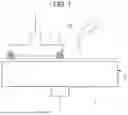
FIG. 1 is a perspective view illustrating a wafer polishing system in accordance with an embodiment;
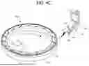
FIG. 2A is a perspective view of a retainer ring in accordance with an embodiment;
FIG. 2B is an enlarged perspective view illustrating a portion “A” of FIG. 2A;
FIGS. 2C, 2D, and 2E are perspective views illustrating various shapes of outer sides in accordance with an embodiment;
FIG. 3A is an operational view illustrating a comparative example of a retainer ring;
FIG. 3B is an operational view illustrating a retainer ring in accordance with an embodiment;
FIGS. 4A, 4B, 4C, and 4D are views illustrating retainer rings in accordance with an embodiment;
FIG. 5 is a plan view illustrating an operation of a retainer ring in accordance with an embodiment;
FIG. 6A is a perspective view illustrating a mold block having an inclined side in accordance with an embodiment;
FIG. 6B is an enlarged perspective view illustrating a portion “A” in FIG. 6A;
FIG. 6C is a cross-sectional view taken along a line b-b′ of FIG. 6B;
FIG. 7A is a perspective view illustrating a mold block having a modified inclined side in accordance with an embodiment;
FIG. 7B is an enlarged perspective view illustrating a portion “A1” in FIG. 7A;
FIG. 7C is a cross-sectional view taken along a line b-b′ of FIG. 7B; and
FIGS. 8A and 8B are views illustrating a first lateral side of a pad contact in accordance with an embodiment.
DETAILED DESCRIPTION
In drawings, sizes and relative proportions of layers and regions may be exaggerated for clarity. Throughout the specification, like reference numerals refer to like components. The word “coupled,” as used herein for some embodiments, means that two components are directly connected with one another. For example, a first component coupled to a second component means the first component is contacting the second component. For other embodiments, coupled components have one or more intervening components. For example, a first component is coupled to a second component when the first and second components are both in contact with a common third component even though the first component is not directly contacting the second component.
An embodiment will be described below in detail with reference to the accompanying drawings.
According to various embodiments, the retainer ring with improved slurry supply performance and the wafer polishing system including the same, as configured above, may prevent or mitigate slurry that may collide with the mold block of the retainer ring from being discharged outward beyond the polishing pad without entering the polishing head. Instead, the slurry may be guided into a groove region formed in the retainer ring, thereby improving an amount of the slurry supplied toward the wafer. As a result, the polishing efficiency of the polishing system may be enhanced.
FIG. 1 is a perspective view illustrating a wafer polishing system in accordance with an embodiment.
Referring to FIG. 1, a wafer polishing system of an embodiment may include a platen 5, a polishing pad 1, a polishing head 2, a slurry supplier 3 and a retainer ring 1000.
The platen 5 may rotate in a first direction R1. The polishing pad 1 may be disposed on an upper side of the platen 5 and may rotate together with the platen 5 in the first direction R1. The slurry supplier 3 may supply slurry onto the polishing pad 1.
The polishing head 2 may be disposed over the platen 5 and may rotate in the same direction R1 as the polishing pad 1. The polishing head 2 may hold a wafer 4 and press the wafer against the polishing pad 1.
The retainer ring 1000 may be disposed over a bottom side of the polishing head 2. The retainer ring 1000 may have a ring shape supporting an outer peripheral side of the wafer 4. The retainer ring 1000, for example, a bottom side of the retainer ring 1000 (e.g., a side contacting the polishing pad 1), may include a plurality of grooves. The slurry may be supplied through the grooves to a space between the wafer 4 and the upper side of the polishing pad 1.
As described above, the slurry may be introduced into the retainer ring 1000 through the grooves of the retainer ring 1000 to polish the side of the wafer 4. The polishing efficiency of the wafer 4 may be proportional to an amount of the slurry supplied into the retainer ring 1000.
Hereinafter, the retainer ring, in an embodiment, capable of improving the slurry supply amount will be described in further detail with reference to the drawings.
FIG. 2A is a perspective view illustrating a retainer ring in accordance with an embodiment, FIG. 2B is an enlarged perspective view illustrating a portion “A” of FIG. 2A, and FIGS. 2C to 2E illustrate various configurations of outer sides of the retainer ring.
For convenience of explanation, FIG. 2A shows the retainer ring 1000 of FIG. 1 in a flipped (180° rotated) orientation. In the following description, an upper side of the retainer ring 1000 refers to a side that contacts the wafer, and a bottom side refers to a side that contacts the polishing head.
As shown in FIGS. 1, 2A, and 2B, the retainer ring 1000 may include a mold block 100 and a coupling block 400.
The mold block 100 may be coupled to an upper side of the coupling block 400. At least one coupling groove 400h may be formed in an upper portion of the coupling block 400. The mold block 100 may be mechanically coupled to the coupling block 400 using the coupling groove 400h and a fastening member (not shown).
The coupling block 400 may be in direct contact with the polishing head 2. For example, a bottom side of the coupling block 400 shown in FIG. 2A may be connected to the bottom side of the polishing head 2 shown in FIG. 1. The coupling block 400 may have a ring shape with a curvature corresponding to a curvature of the outer periphery of the wafer 4, but is not limited thereto.
The mold block 100 may include a portion configured to directly contact the polishing pad 1. The mold block 100 may include a body 110, a plurality of slurry passages 120, a plurality of pad contacts 130 and a plurality of slurry guides 140.
The body 110 may have a substantially ring-shaped structure, including an upper side and a bottom side. For example, the body 110 having the ring shape may include a width configured to support an outer circumferential side of the wafer. The bottom side of the body 110 may be mechanically coupled to the upper side of the coupling block 400. For example, a shape of the body 110 may correspond to the shape of the coupling block 400. That is, the shape of the coupling block 400 may include a ring-shape structure.
The pad contacts 130 may be disposed over the upper side of the body 110. The pad contacts 130 may be arranged along a circumferential direction of the body 110 with predetermined intervals. The spaces between the adjacent pad contacts 130 may correspond to the slurry passages 120. The word “predetermined” as used herein with respect to a parameter, such as a predetermined interval(s), means that a value for the parameter is determined prior to the parameter being used in a process or algorithm. For some embodiments, the value for the parameter is determined before the process or algorithm begins. In other embodiments, the value for the parameter is determined during the process or algorithm but before the parameter is used in the process or algorithm.
Each slurry passage 120 may be formed to extend from an outer circumferential side 110a toward the inner circumferential side 110b of the body 110 to provide slurry to the polishing pad 1.
The slurry passage 120 may have an inclined configuration aligned with the rotation direction R1 of the polishing head 2. In an embodiment, an extension direction (e.g., longitudinal direction) of the slurry passage 120 may be substantially perpendicular to the rotation direction R1.
The pad contacts 130 may be integrally formed with the body 110. Alternately, the pad contacts 130 may be separately fabricated from the body 110 and then attached to the upper side of the body 110. In an embodiment, for illustrative clarity, the pad contacts 130 and the body 110 may be described as separate components, but if the materials are the same, they may be formed integrally.
Each of the pad contacts 130 may include a first lateral side 131, a second lateral side 132, a pad attachment side CS, an outer side 133 and an inner side 134. For example, the first lateral side 131 may be located on a rear side of a pad contact 130 with respect to the rotation direction R1 of the polishing head 2. The second lateral side 132 may be located on a front side of a pad contact 130 with respect to the rotation direction R1 and face the first lateral side 131. The second lateral side 132 may have a larger cross-sectional area than the first lateral side 131. The outer side 133 may connect the outer edges of the first and second lateral sides. The inner side 134 may connect the inner edges of the first and second lateral sides.
The pad attachment side CS may be a flat plane connecting upper edges of the first and second lateral sides 131 and 132. The pad attachment side CS may directly contact the polishing pad 1.
For example, longitudinal axes of the outer side 133 and the inner side 134 may be parallel to the rotation direction R1 of the polishing head 2. For example, the outer side 133 may be located close to the outer circumferential side 110a of the body 110. The inner side 134 may be positioned adjacent to the inner circumferential side 110b of the body 110 or the outer periphery of the wafer 4.
Each slurry guide 140 may be formed on the outer circumferential side 110a of the body 110. The slurry guide 140 may define a space having a gradually expanding width Wg in a direction opposite to the rotation direction −R1 of the polishing head 2. For example, a region having a maximum width Wg_max in the slurry guide 140 may be in communication with the slurry passage 120, thereby forming an expanded slurry passage SP. In an embodiment, the slurry guide 140 may have a triangular prism shape.
As such, the slurry passage SP, which includes the slurry passage 120 and the slurry guide 140, may have a gradually increasing width SPW toward the outer circumferential side 110a of the body 110. In other words, the width SPW of the slurry passage SP may gradually decrease from the outer circumferential side 110a of the body 110 toward the inner circumferential side 110b of the body 110.
In an embodiment, by being adjacent to the first lateral side 131 of the pad contact 130, the slurry guide 140 may facilitate an inflow of the slurry from the outer side of the body 110 to the inner side where the wafer 4 may be located, especially during the rotation of the polishing head 2. In an embodiment, by being adjacent to the first lateral side 131 of the pad contact 130, the slurry guide 140 may facilitate an inflow of the slurry from the outer side of the body 110 (e.g., outer circumferential side 110a) to the inner side (e.g., inner circumferential side 110b) where the wafer 4 may be located, especially during the rotation of the polishing head 2.
In an embodiment, the first lateral side 131 may be designed to have a smaller cross-sectional area than the second lateral side 132, thereby increasing the exposed area of the body 110 toward the rear side (−R1), and consequently increasing the volume of the slurry guide 140.
In an embodiment, a length d1 of an upper edge of the first lateral side 131 may be substantially equal to a length of a bottom edge of the first lateral side 131. A length d2 of an upper edge of the second lateral side 132 may be substantially equal to a length of a bottom edge of the second lateral side 132. The length d1 of the upper (or bottom) edge of the first lateral side 131 may correspond to about 0.1% to about 85% of a width d0 of the body 110, defined as a distance from an outer circumferential side 110a to an inner circumferential side 110b of the body 110. The length d2 of the upper edge of the second lateral side 132 may be about 95% to about 100% of the width d0 of the body 110.
As such, because the cross-sectional area of the first lateral side 131 may be designed to be smaller than that of the second lateral side 132, the exposed area of the body 110 may increase toward the first lateral side 131 from the second lateral side 132 (e.g., in the reverse rotational direction −R1) with respect to one pad contact 130. Accordingly, a volume of the slurry guide 140 may increase. Here, the slurry guide 140 may be understood as a space between the outer side 133 of the pad contact 130 and an upper region of the body 110.
For reference, the first lateral side 131, the second lateral side 132, the outer side 133 and the inner side 134 may each be planar and substantially perpendicular to the upper side of the body 110 and a pad attachment side CS.
As described above, the slurry guide 140 may be in communication with the slurry passage 120, and the slurry passage SP having a wider gap than the slurry passage 120 may be provided in the retainer ring 1000. Accordingly, in an embodiment, upon rotation of the polishing head 2, a greater amount of slurry located at the outer periphery of the retainer ring 1000 (or of the outer circumferential side 110a of the body portion) may be guided toward the inner circumferential side 110b of the body portion 110.
In particular, in an embodiment, because the slurry guide 140 may be provided adjacent to the first lateral side 131, the slurry passage SP may have a laterally asymmetric structure favorable for slurry inflow with respect to the slurry transfer portion 120.
Due to the presence of the slurry guide 140, a bent portion B may be formed on the outer side 133 of the pad contact 130, as illustrated in FIG. 2C. For example, the bent portion B of the outer side 133 may result from a difference in cross-sectional area between the first lateral side 131 and the second lateral side 132.
Referring to the bent portion B, a first region 133-1 of the outer side 133 adjacent to the first lateral side 131 may be in contact with the slurry guide 140. In other words, the first region 133-1 of the outer side 133 may define the slurry guide 140. A second region 133-2 of the outer side 133, adjacent to the second lateral side 132 with reference to the bent portion B, may be positioned on substantially the same plane as the outer circumferential side 110a of the body 110, thereby forming the outer side of the retainer ring 1000. The term “inside” shown in the drawing refers to a direction toward the inner circumferential side 110b or toward the wafer, whereas “outside” refers to an outer direction of the retainer ring 1000. However, the present disclosure is not limited thereto. If the second region 133-2 may be located further inward than the outer circumferential side 110a of the body 110, the second region 133-2 may also be understood as being in contact with the slurry guide 140.
As shown in FIG. 2D, in an embodiment, a bent portion B1 may be rounded toward the outside direction, such that the outer side 133 may have a convex curvature. Meanwhile, as illustrated in FIG. 2E, in an embodiment, a bent portion B2 may be rounded toward the inside direction, such that the outer side 133 may have a concave curvature.
FIG. 3A is an operational view illustrating a comparative example of a retainer ring, and FIG. 3B is an operational view illustrating a retainer ring in accordance with an embodiment.
As shown in FIG. 3A, in a comparative example of a retainer ring structure in which slurry passages 12 of uniform width may be provided between a plurality of pad contacts 13, slurry remaining on the outer side of a mold block 10 may only flow inward through the slurry passages 12. Particularly, because the slurry passages 12 may be formed in a substantially straight configuration, the slurry may collide with and bounce off the outer side 16 of the pad contacts 13 (as indicated by arrow A1). The residual slurry may generate a slurry bow wave phenomenon, which may reduce polishing efficiency.
Apart from this, as shown in FIG. 3B, in an embodiment, when the slurry guide 140 is provided adjacently to the first lateral side 131 and the outer side 133 of the pad contact 130, the expanded slurry passage SP may be formed. As a result, in an embodiment, slurry remaining on the outer side of the mold block 100 may effectively flow into the slurry passage 120 through the slurry guide 140 (as indicated by arrow A2).
FIGS. 4A through 4D illustrate various modified embodiments of the retainer ring.
Referring to FIG. 4A, a retainer ring 1000a may include a molding block 100a and a coupling block 400. The molding block 100a may include a body 110, a plurality of slurry passages 120, a plurality of pad contacts 130a and a plurality of slurry guides 140a.
Each slurry passage 120 may be located between a pair of adjacent pad contacts 130a. Each pad contact 130a may include a first lateral side 131a, a second lateral side 132a, an outer side 133a and an inner side 134a.
An upper edge length d1a of the first lateral side 131a may be substantially equal to a bottom edge length of the first lateral side 131a. Similarly, an upper edge length d2a of the second lateral side 132a may be substantially equal to a bottom edge length of the second lateral side 132a. In an embodiment, the upper edge length d1a of the first lateral side 131a may be configured to be about 50% to about 60% of the width d0 of the body 110, and the upper edge length d2a of the second lateral side 132a may be about 95% to about 100% of the width d0.
Due to the difference in length between the first and second lateral sides 131a and 132a, the slurry guide 140a may be formed between the outer side 133a of the pad contact 130a adjacent to the first lateral side 131a and the outer circumferential side 110a of the body 110.
Accordingly, a width wg1 of the slurry guide 140a may gradually increase from the second lateral side 132a toward the first lateral side 131a. In an embodiment, because the slurry guide 140a may be in communication with the slurry passage 120, an inlet of the slurry passage SP of the retainer ring 1000a may be effectively widened. In an embodiment, an upper edge of the outer side 133a may be formed with a curvature.
Referring to FIG. 4B, a retainer ring 1000b may also include a molding block 100b and a coupling block 400. The molding block 100b may include a body 110, a plurality of slurry passages 120, a plurality of pad contacts 130b and a plurality of slurry guides 140b.
The pad contacts 130b may each include a first lateral side 131b, a second lateral side 132b, an outer side 133b, an inner side 134b and a pad attachment side CS. In an embodiment, lengths d1b of the upper and bottom edges of the first lateral side 131b may be significantly smaller than lengths d2b of the upper and bottom edges of the second lateral side 132b. For example, d1b may be about 0.1% to about 15% of the width d0 of the body 110, and d2b may be about 95% to about 100% of d0.
Accordingly, a width wg2 of the slurry guide 140b may be greater than wg1 of FIG. 4A. For instance, in an embodiment, the upper and bottom edges of the outer side 133b may be processed to have a uniform curvature.
In an embodiment, at least a portion of the first lateral side 131b, for example the upper edge of the first lateral side 131b may be rounded. This configuration, in an embodiment, may help prevent or mitigate polishing defects or damage to the retainer ring 1000a or 1000b during the polishing process.
Referring to FIG. 4C, a retainer ring 1000c may have a configuration similar to that of the retainer ring 1000b, except that the outer side 133c of the pad contact 130c and the slurry guide 140c may have different structures.
In FIG. 4C, the outer side 133c of the pad contact 130c may have a substantially flat plane perpendicular to the pad attachment side, with no bend (B) or curvature. For example, the upper and bottom edges of the outer side 133c may form straight lines parallel to the tangents of the outer circumferential side 110a of the body 110. Consequently, the edges of the slurry guide 140c in contact with the outer side 133c may also have a substantially rectangular planar structure. From a top view, the outer side 133c may extend linearly.
FIG. 4D illustrates various configurations in which the length of the first lateral side 131 of the pad contact 130 may vary from da to dd, where d0>da>db>dc>dd. Accordingly, the shape of the slurry guide 140 may also vary.
FIG. 5 is a plan view illustrating an operation of a retainer ring in accordance with an embodiment.
Referring to FIG. 5, the retainer ring 1000 may include a slurry guide 140 disposed adjacent to the outer side 133 of the pad contact 130. The slurry guide 140 may be configured to have a width that gradually expands in a direction opposite to the rotation direction −R1 of the polishing head 2 (see FIG. 1), which differs from the rotation direction R1 by 180°. Accordingly, in an embodiment, during the polishing process, the slurry inflow volume increases by the volume of the slurry guide 140, improving polishing efficiency. The slurry guide 140, being located on the outer edge of the retainer ring 1000, also, in an embodiment, prevents or mitigates slurry residue and reduces the occurrence of slurry bow wave phenomena.
FIGS. 6A to 6C illustrate a mold block having an inclined side in accordance with an embodiment.
Referring to FIGS. 6A to 6C, a mold block 200 may include a body 210, a plurality of slurry passages 220, a plurality of pad contacts 230 and a plurality of slurry guides 240.
Each pad contact 230 may include a first lateral side 231, a second lateral side 232, an outer side 233, an inner side 234, a pad attachment side CS and an inclined side 235. The inclined side 235 may be disposed between the pad attachment side CS and the outer side 233 of the pad contact 230. The inclined side 235 may have a chamfer shape and be sloped relative to both the pad attachment side CS and the outer side 233. The slope (θ) and shape of the inclined side 235 may be variable depending on the required amount of slurry during the polishing process. In an embodiment, the pad attachment side CS may remain flat and maintain a uniform thickness.
In an embodiment, the inclined side 235 may have a rectangular planar structure, such that an upper edge length d1U of the first lateral side 231 may be shorter than a bottom edge length d1L. The upper edge length d2U of the second lateral side 232 may be greater than d1U but smaller than its own bottom edge length d2L. The bottom edge length d2L may be equal to or slightly less than the body width d0. For instance, the upper edge length d1U of the first lateral side 231 may range from about 0.1% to about 85% of the body width d0. The outer side 233 may maintain a uniform height.
As such, the chamfered inclined side 235 may extend the slurry guide space 240 up to the side of the inclined portion. Consequently, in an embodiment, a greater amount of slurry may flow into the retainer ring via the slurry guide 240 and the slurry passage 220.
FIGS. 7A to 7C show a mold block with a modified inclined side in accordance with an embodiment.
Referring to FIGS. 7A to 7C, a mold block 200a may include a body 210, a plurality of slurry passages 220, a plurality of pad contacts 230a and a plurality of slurry guides 240a.
Each pad contact 230a may include a first lateral side 231a, a second lateral side 232a, an outer side 233a, an inner side 234a, a pad attachment side CS and a modified inclined side 235a. The inclined side 235a may be formed in a chamfered shape at the interface between the pad attachment side CS and the outer side 233a. The slope of the inclined side 235a may vary by position. For example, the inclination angle θ1 of the inclined side 235a adjacent to the first lateral side 231a may be shallower than the inclination angle θ2 of the inclined side adjacent to the second lateral side 232a.
As a result, in an embodiment, an upper edge length d11U of the first lateral side 231a may be significantly shorter than a bottom edge length d11L. An upper edge length d21U of the second lateral side 232a may be greater than d11L. In an embodiment, a bottom edge length d21L of the second lateral side 232a may be greater than d21U and equal to or slightly less than the body width d0.
Thus, the pad attachment side CS may maintain a constant height, while the thickness of the outer side 233a gradually decreases toward the first lateral side 231a due to the inclined side 235a. This increases the area and volume of the slurry guide 240a adjacent to the first lateral side 231a, allowing a larger amount of slurry to flow into the interior of the mold block 200a through the slurry passage 220.
FIGS. 8A and 8B illustrate additional variations of the inclined side of a pad contact.
In FIG. 8A, a pad contact 230b may include an inclined side 235b. The inclined side 235b of a pad contact 230b may be formed in a convex shape protruding outward. Alternatively, as shown in FIG. 8B, an inclined side 235b′ may be formed in a concave shape recessed inward.
In one example, at least one of the following corners may be rounded, for example, a corner E1 where the outer side 233b and the inclined side 235b (or 235b′) meet, a corner E2 where the inclined side 235b (or 235b′) and the pad attachment side CS meet, a corner E3 where the pad attachment side CS and the inner side 234b meet.
The planar configuration of the inclined side 235b or 235b′ may correspond to that shown in either FIG. 6B or FIG. 7B.
According to an embodiment, the retainer ring includes a slurry guide with an expanded width that communicates with the slurry passage, considering the rotation direction of the polishing head. In an embodiment, this configuration increases the slurry inflow volume, improves polishing efficiency, and reduces the slurry bow wave phenomenon.
As described above, it will be understood by those skilled in the art that the present disclosure may be implemented in other specific forms without changing the technical idea or essential features. Therefore, the above-described embodiments should be understood as illustrative in all respects and not as restrictive.
Claims
What is claimed is:1. A retainer ring comprising:
a coupling block configured to be coupled to a polishing head; and
a mold block coupled to the coupling block to support a wafer positioned on a polishing pad and to contact the polishing pad,
wherein the mold block comprises:
a body coupled to the coupling block;
a plurality of pad contacts disposed over an upper side of the body and configured to contact the polishing pad;
a plurality of slurry passages formed between the plurality of pad contacts and configured to allow a slurry to flow from an outer circumferential side of the body to an inner circumferential side of the body; and
a plurality of slurry guides respectively disposed over outer sides of the pad contacts located on a rear side, with respect to a rotational direction of the polishing head, of the pad contacts,
wherein each slurry guide intersects a respective slurry passage, and the slurry passage has a width that increases in a direction opposite to the rotational direction of the polishing head by the slurry guide.
2. The retainer ring of claim 1, wherein the body has a ring shape with a width configured to support an outer circumferential side of the wafer.
3. The retainer ring of claim 1, wherein each of the pad contacts comprises:
a first lateral side located on the rear side in the rotational direction of the polishing head;
a second lateral side located on a front side which is opposite to the rear side, and facing the first lateral side, the second lateral side having a cross-sectional area greater than that of the first lateral side;
a pad attachment side connecting upper edges of the first and second lateral sides and configured to contact the polishing pad; and
an outer side disposed adjacent to the outer circumferential side of the body and located between the first lateral side, the second lateral side and the pad attachment side.
4. The retainer ring of claim 3,
wherein a length of an upper edge of the first lateral side is equal to a length of a bottom edge of the first lateral side,
wherein a length of an upper edge of the second lateral side is equal to a length of a bottom edge of the second lateral side, and
wherein the length of the upper edge of the first lateral side is less than the length of the upper edge of the second lateral side.
5. The retainer ring of claim 3, wherein a length of the upper edge of the first lateral side is 0.1% to 85% of a width of the body.
6. The retainer ring of claim 3, wherein an edge where the upper edge of the first lateral side meets the pad attachment side is rounded.
7. The retainer ring of claim 3, wherein the outer side includes a bent portion generated by the slurry guide.
8. The retainer ring of claim 3, wherein an upper edge of the outer side is linear.
9. The retainer ring of claim 3, wherein an upper edge of the outer side is curved.
10. The retainer ring of claim 3, wherein the pad contact further comprises an inclined side disposed between the pad attachment side and the outer side, the inclined side having a slope with respect to both the pad attachment side and the outer side.
11. The retainer ring of claim 10, wherein the inclined side has a chamfer shape.
12. The retainer ring of claim 10, wherein the inclined side comprises a planar structure having curvature toward an outer or inner direction.
13. The retainer ring of claim 10,
wherein a length of an upper edge of the first lateral side is less than a length of a bottom edge of the first lateral side, and
wherein a length of an upper edge of the second lateral side is equal to or greater than the upper edge length of the first lateral side and less than a bottom edge length of the second lateral side.
14. The retainer ring of claim 10,
wherein the pad attachment side has substantially a uniform height from an upper side of the body, and
wherein the outer side has substantially a uniform thickness.
15. The retainer ring of claim 10,
wherein the pad attachment side has substantially a uniform height from an upper side of the body, and
wherein the outer side has a thickness that decreases toward the first lateral side.
16. A wafer polishing system comprising:
a polishing pad;
a polishing head disposed over the polishing pad and configured to press a wafer against the polishing pad; and
a retainer ring mounted to the polishing head and configured to support the wafer,
wherein the retainer ring comprises:
a body having an outer circumferential side and an inner circumferential side;
a plurality of pad contacts disposed on an upper side of the body and configured to contact the polishing pad; and
a plurality of slurry passages formed between the plurality of pad contacts and configured to introduce a slurry onto the polishing pad,
wherein each of the slurry passages has an asymmetric upper side structure including a width on the outer circumferential side of the body being greater than a width on the inner circumferential side and increases in a direction opposite to a rotational direction of the polishing head.
17. The wafer polishing system of claim 16, wherein the retainer ring comprises:
a coupling block coupled to the polishing head; and
a mold block coupled to the coupling block and configured to support the wafer and contact the polishing pad,
wherein the mold block comprises the body, the plurality of pad contacts and the plurality of slurry passages.
18. The wafer polishing system of claim 16, wherein each of the pad contacts comprises:
a first lateral side located on a rear side in the rotational direction of the polishing head;
a second lateral side located on a front side in the rotational direction and facing the first lateral side, the second lateral side having a greater cross-sectional area than the first lateral side;
a pad attachment side connecting upper edges of the first and second lateral sides and configured to contact the polishing pad; and
an outer side disposed adjacent to the outer circumferential side of the body and located between the first lateral side, the second lateral side, and the pad attachment side.
19. The wafer polishing system ring of claim 18, wherein each of the pad contacts further comprises an inclined side disposed between the pad attachment side and the outer side, the inclined side having a slope with respect to both the pad attachment side and the outer side.
Images & Drawings included:


Sources:
- United States Patent and Trademark Office - verify current appl. status at the USPTO↗
Similar patent applications:
Recent applications in this class:
- » 20260097466 2026-04-09
RETAINER RING AND WAFER POLISHING SYSTEM INCLUDING THE RETAINER RING - » 20260061550 2026-03-05
RETAINING RING FOR CMP - » 20260048473 2026-02-19
WAFER POLISHING EQUIPMENT - » 20260014669 2026-01-15
POLISHING HEAD ASSEMBLIES FOR POLISHING SEMICONDUCTOR WAFERS - » 20260014668 2026-01-15
RETAINER RING, POLISHING HEAD ASSEMBLY INCLUDING THE RETAINER RING, AND POLISHING DEVICE INCLUDING THE POLISHING HEAD ASSEMBLY - » 20260008150 2026-01-08
RETAINING RING HAVING INNER SURFACES WITH FEATURES - » 20260001193 2026-01-01
RETAINER RING FOR POLISHING HEAD - » 20260001192 2026-01-01
POLISHING HEAD AND POLISHING TREATMENT DEVICE - » 20250312886 2025-10-09
DEVICE AND METHOD FOR IMPROVED CMP PROCESS WITH CMP HEAD - » 20250269489 2025-08-28
CARRIER HEAD AND SUBSTRATE POLISHING APPARATUS INCLUDING THE SAME
Recent applications for this Assignee:
- » 20260101788 2026-04-09
SEMICONDUCTOR PACKAGE INCLUDING A MOLDED UNDERFILL STRUCTURE, AND A PACKAGE SUBSTRATE - » 20260101517 2026-04-09
SEMICONDUCTOR DEVICE - » 20260101515 2026-04-09
SEMICONDUCTOR DEVICE AND MANUFACTURING METHOD OF SEMICONDUCTOR DEVICE - » 20260101509 2026-04-09
SEMICONDUCTOR DEVICE AND METHOD OF MANUFACTURING THE SEMICONDUCTOR DEVICE - » 20260101504 2026-04-09
SEMICONDUCTOR DEVICE AND MANUFACTURING METHOD OF SEMICONDUCTOR DEVICE - » 20260101127 2026-04-09
IMAGE SENSING DEVICE - » 20260099163 2026-04-09
SEMICONDUCTOR DEVICE - » 20260097466 2026-04-09
RETAINER RING AND WAFER POLISHING SYSTEM INCLUDING THE RETAINER RING - » 20260096466 2026-04-02
SEMICONDUCTOR PACKAGE INCLUDING A MOLDED UNDERFILL STRUCTURE, AND A PACKAGE SUBSTRATE - » 20260090472 2026-03-26
METHOD OF MANUFACTURING A SEMICONDUCTOR PACKAGE