ECCENTRIC SCREW PUMP
US20260098535A1
2026-04-09
19/311,209
2025-08-27
Smart Summary: An eccentric screw pump uses a special screw-shaped rotor that turns to create different pump chambers. The rotor works inside a flexible tube made from a rubber-like material. This tube is attached to a metal pipe for support. A sensor is built into the tube, and it cannot be removed because it is bonded through a heating process called vulcanization. This design helps the pump operate efficiently while also allowing for monitoring through the sensor. 🚀 TL;DR
Abstract:
An eccentric screw pump with a helical rotor and a stator made of an elastomer material, in which the rotor rotates by forming several pump chambers, wherein the stator is vulcanized into a preferably metal support pipe, wherein the stator has at least one sensor, which is inseparably connected to the stator, wherein the inseparable connection between the stator and senor is made by vulcanization.
Inventors:
- Martin Zierhofer 3 🇩🇪 Aschau am Inn, Germany
- Frank Götz 2 🇩🇪 Polling, Germany
- Mikael Tekneyan 1 🇩🇪 Kraiburg, Germany
- Bettina Steinberger 1 🇩🇪 Obertaufkirchen, Germany
Applicant:
Interested in similar patents?
Get notified when new applications in this technology area are published.
Classification:
F04C2/1071 » CPC main
Rotary-piston machines or pumps of intermeshing-engagement type, i.e. with engagement of co-operating members similar to that of toothed gearing of internal-axis type with the outer member having more teeth or tooth-equivalents, e.g. rollers, than the inner member with helical teeth the inner and outer member having a different number of threads and one of the two being made of elastic materials, e.g. Moineau type
F04C2240/10 » CPC further
Components Stators
F04C2240/803 » CPC further
Components; Other components Electric connectors or cables; Fittings therefor
F04C2240/81 » CPC further
Components; Other components Sensor, e.g. electronic sensor for control or monitoring
F04C2270/19 » CPC further
Control; Monitoring or safety arrangements Temperature
F04C2/107 IPC
Rotary-piston machines or pumps of intermeshing-engagement type, i.e. with engagement of co-operating members similar to that of toothed gearing of internal-axis type with the outer member having more teeth or tooth-equivalents, e.g. rollers, than the inner member with helical teeth
Description
TECHNICAL FIELD
The invention relates to an eccentric screw pump and a method for producing an eccentric screw pump.
BACKGROUND
For the most part, individual, high-priced industrial sensors, which are attached retroactively to machines or systems, are currently used on pumps and on pump systems in order to record data during the operation.
A sufficient application is not known here especially for stators of eccentric screw pumps. For the most part, only individual PT100 temperature sensors are attached retroactively to the stator. They are used as dry running protection. Where further operating data is to be recorded, it is not unusual to install high-priced industrial sensors to the pump outside of the rubber-elastic stator lining.
Insofar as individual sensors are currently already installed in eccentric screw pumps and corresponding systems, the wiring thereof is often problematic.
In the case of the stators of eccentric screw pumps, a STP2 temperature sensor is, for the most part, introduced retroactively, whereby a retroactive machine processing of the stator and, for the most part, also of the support pipe holding the stator, is necessary here. This leads to an additional manufacturing effort.
Due to the fact that these sensors—as mentioned—are very expensive, many customers tend to order eccentric screw pumps without the corresponding sensors. On the one hand, this has the result that possible errors or overloads of the eccentric screw pump are not detected or are detected too late during operation. In practice, this consistently results in an unnecessarily shortened service life of the pump.
It is a further aspect, which is relevant from time to time, that an embodiment without sensor system makes it easy for product pirates to be able to offer copied stators.
To date, possible measuring technology, with which a stator is equipped, is attached retroactively after the production of the stator. It is common for this purpose to radially drill through the finished stator. For the most part, the actual housing-forming metal support pipe for the stator is thereby also drilled through. A metal sleeve with an external thread, which, in turn, receives the respective sensor, is then screwed into the stator. This metal sleeve additionally also has the task of sealing the stator. The cables of the sensor leave the metal sleeve on its side facing away from the rotor and are then pulled outwards through the metal support pipe for the stator.
The metal sleeve is typically screwed into the stator so that it is anchored only in the elastomer material of the stator and not also in the metal support pipe. The metal sleeve thus does not obstruct in particular the radial expansion movements of the stator. However, as mentioned, this leads to a significantly increased manufacturing effort, which increases costs unnecessarily.
SUMMARY
In light of the foregoing, it is the object of the invention to specify a means, with which data of an eccentric screw pump can be detected easily and cost-efficiently during operation.
A solution to this object is provided by the main claim.
According to the invention, an eccentric screw pump with a helical rotor and a stator made of an elastomer material is proposed for this purpose, in which the rotor rotates by forming several pump chambers. The stator is hereby vulcanized into a preferably metal support pipe. The eccentric screw pump is characterized in that the stator has at least one sensor, which is inseparably connected to the stator—i.e., is completely vulcanized therein or is vulcanized therein at least partly or on one side in a flat manner, respectively, i.e., at the edge thereof or at the transition between the stator (thus the lining) and the support pipe, respectively. In its broadest sense, “being vulcanized into” means being enclosed at its installation location by means of vulcanization here. In this context, “inseparably connected” means that the at least one sensor cannot be removed from the stator, without damages occurring at least to the elastomer material of the stator, even though they may be reparable.
The mentioned vulcanization of the at least one sensor hereby preferably takes place simultaneously with the manufacture of the stator itself. In general, the manufacturing effort can thus be reduced significantly because no additional manufacturing steps and no retroactive machine processing of the stator are necessary.
Due to an embedding of the sensors in such a way, it is additionally possible to use significantly more cost-efficient sensors. Moreover, the stator according to the invention can be recognized more clearly as original compared to copied stators. This applies at least when the ID is encrypted and can be verified via certificates.
It is a preferred embodiment variation that the at least one sensor is designed, attached and connected so that during the vulcanization of the stator into the support pipe assigned to it, it already delivers meaningful data, in evaluable form. The process of vulcanization can thus be monitored directly and live. Moreover, it is possible—and in particular when a storage is also vulcanized—to track during the entire service life of the eccentric screw pump, which influence certain process data of the vulcanization has on the eccentric screw pump. It can thus be checked whether the critical production process of vulcanization was okay, and the return flow can be discharged from the field, which can possibly still be optimized in response to the vulcanization.
A possible dry run can additionally be detected better on the basis of the process data from manufacture and the operating data of the stator.
It is furthermore particularly preferred when the at least one sensor is fixed to the inner circumferential surface of the support pipe. It can therefore be fixed completely or essentially or at least more than only on a smaller portion of its surface, respectively. As a rule, this “fixing” is a fixation, which is independent of the vulcanization. This preferably takes place by means of an adhering of the at least one sensor to the metal support pipe, particularly preferably on the inner circumferential side facing the stator. On the one hand, the at least one sensor is securely connected to the support pipe by means of this fixing during the vulcanization process and is not unintentionally “swept away” during the vulcanization. On the other hand, the metal support pipe acts as cooling body during the vulcanization and thus decreases the thermal stress on the sensor. Said thermal stress is shortened at least temporarily because the support pipe has to also heat up first. Ideally, an adhesive is used, which improves the heat transfer between the sensor and the support pipe.
In addition, it is particularly preferred when the at least one sensor is covered by an additional plastic seal. This plastic seal is preferably provided only after the fastening of the at least one sensor to the support pipe. Prior to the application and preferably also after the application, the plastic seal is in a geometrically undefined state and is preferably also applied like paint or sealing material. This is preferably a liquid or pasty plastic seal, which hardens only after the application. On the one hand, the plastic seal securely holds the at least one sensor in position. On the other hand, it also serves to shield against direct contact with the liquid elastomer material, which is introduced for the vulcanization.
It is a further preferred embodiment that a connection cable of the at least one sensor is guided out of the elastomer material of the stator all the way to the accessible outer side of the support pipe; preferably over the front ring surface of the support pipe, which is ideally provided for this purpose with a local recess, which forms a passage for the connection cable, wherein the connection cable is also vulcanized into the elastomer material of the stator area by area. A further connection of the at least one sensor is thus easily possible. Said connection cable preferably has the task of emitting the signal to the outside and of optionally also supplying the sensor with energy. In the case of an arrangement of this type, the portion of the connection cable, which merges into the connection plug, additionally also experiences a strain relief in a very simple and effective manner.
It is additionally particularly preferred when the at least one sensor is arranged on a flexible printed circuit board, which is adhered with its side facing away from the stator to the inner circumferential surface of the support pipe. The flexible conductor surface thus forms an absolutely flat/level adhesive surface, which allows for a large-area adhesion. This furthermore contributes to the simplicity and cost savings of the entire system.
It is furthermore particularly preferred when the flexible printed circuit board is coated with a PSA (Pressure Sensitive Adhesive) on its side facing away from the stator. This PSA is preferably self-adhesive without hardening and is applied like a “sticker”. A very simple and quick assembly without hardening time is thus possible after the assembly.
It is additionally preferred that the connection cable and/or the connection cables to further sensors are also embodied as flexible printed circuit board with printed conductor tracks, wherein the flexible printed circuit board is preferably formed in one piece as a whole or at least across several sensors. This furthermore contributes to the simplicity and cost savings of the entire system. Such a flexible conductor track can be adhered to the support pipe more easily and more securely due to its flatness.
It is moreover particularly preferred that an eccentric screw pump is equipped with several sensors, which are positioned so as to be spaced apart from one another more than only insignificantly. This more than only insignificant spacing exists when a sensor is at least 10 mm, preferably at least 20 mm, but maximally 200 mm spaced apart from its adjacent sensor. It is preferred in the case of eccentric screw pumps of this type that the sensors—compared to one another—are covered with elastomer material of the stator with varying thickness. This means that not only are several sensors provided, which are always attached at generally the same location of the respective chamber in the respective pump chambers, their position does in fact vary in the respective pump chamber. Different pressures and/or temperatures can be detected and compared hereby in the different regions of the pump chambers, in order to find out, for example, which region is most heavily loaded.
A further preferred embodiment is that in addition to the at least one sensor, a data storage is also vulcanized, on which data can be stored-preferably in an encrypted or password-protected manner. The system is preferably designed so that data, such as, for example, an electronic nameplate and/or an operating log, can in fact be stored and saved.
It is furthermore particularly preferred when several different sensors are provided, preferably at least two from the group of the pressure sensors, the strain sensors and the inductive sensors. The eccentric screw pump can thus be monitored in many different regions, whereby errors and/or improvement options can be recognized quickly.
Further possible designs, functions and advantages follow from the dependent claims and/or the following description of the exemplary embodiment and/or with reference to the FIGS.
BRIEF DESCRIPTION OF THE DRAWINGS
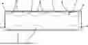
FIG. 1 shows a cross-section of the stator 1 with the exemplary position of the individual sensors 3 on a flexible printed circuit board.
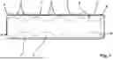
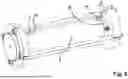
FIG. 2 shows the support pipe without stator with fixed printed circuit board and guided-out connection cable and connection plug in three-dimensional view.
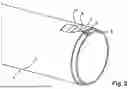
FIG. 3 shows the support pipe without stator with fixed printed circuit board and guided-out connection cable and connection plug analogously to FIG. 2 in modified three-dimensional view.
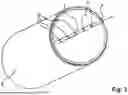
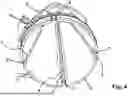
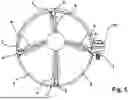
FIG. 4 shows a support pipe with four flexible printed circuit boards arranged on the circumference of the stator in three-dimensional view.
FIG. 5 shows a support pipe with four flexible printed circuit boards arranged on the circumference of the stator in each case with a plastic seal in three-dimensional view
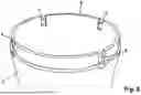
FIG. 6 shows a support pipe with recesses on the front ring surface in three-dimensional view.
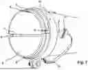
FIG. 7 shows a support pipe analogously to FIG. 5 with four flexible printed circuit boards arranged on the circumference of the stator from a different three-dimensional view.
FIG. 8 shows the stator in the vulcanization form in three-dimensional view.
DETAILED DESCRIPTION
According to the invention, cost-efficient sensors 3 (including evaluation unit and gateway) are preferably used in general.
The sensors 3 are preferably NTC sensors for measuring the temperature. Based on a temperature of 150° C. in the vulcanization bath during the vulcanization of the stator 1, sensors 3 of this type with corresponding temperature resistance have to be selected. Several of these sensors 3 are preferably positioned in a row on a flexible plastic tape, on which the conductor tracks are also located. The mentioned flexible printed circuit board 7 is thus created. In addition, the flexible printed circuit board 7 preferably has at least one connection cable 5 as well as a plug connection, preferably in the form of a connection plug 11, in order to be able to establish the connection to the evaluation unit. The sensors 3 are preferably coated with a plastic seal 4 made of epoxy resin for protection against the liquid in the vulcanization bath. The production of the printed circuits preferably takes place very cost-efficiently by means of a rotary printing process.
These flexible printed circuit boards 7 can also be equipped in a freely selectable manner with other sensors 3, such as magnetometers (e.g., use in the stator possible for the measurement of the rotor rotations), acceleration sensors (e.g., use in the stator for the analysis of vibrations), pressure sensors or ID chips. The length as well as number and type of the sensor system can be configured freely, depending on the application.
According to the invention, these flexible printed circuit boards 7 with sensors 3 attached thereto, subsequent connection cables 5 and connection plug 11 are integrated into the stator 1, preferably vulcanized therein. The stator 1 is hereby attached in a preferably metal support pipe 2, preferably vulcanized into this support pipe 2.
FIG. 1 shows a cross-section of the stator 1 with the exemplary position or arrangement, respectively, of the individual sensors 3 on a flexible printed circuit board 7, in this case preferably temperature sensors as well as the respective strengths of the elastomer element above the respective sensors at the sensor locations. As mentioned, it is preferred that the sensors 3—compared to one another—are covered with elastomer material of the stator 1 with varying thickness. This means that not just several sensors 3 are provided, which are always attached at generally the same location of the respective chamber in the respective pump chambers, their position does in fact vary in the respective pump chamber. Different pressures and/or temperatures can be detected in the different regions of the pump chambers hereby, in order to find out, for example, which region is most heavily loaded.
In addition, a STP2 sensor 9 is shown in FIG. 1, which was provided in the stator 1 according to the prior art prior to this invention.
According to the invention, the flexible printed circuit board 7 is at least partly vulcanized in the stator 1. The connection cable 5 is hereby preferably only partly vulcanized and the connection plug 11 is not vulcanized at all. At one end of the support pipe 2, the connection cable 5 is guided out of the stator 1, on which the connection plug 11 sits. The position of the connection plug 11 as well as of the fixed printed circuit board 7 is illustrated schematically in FIG. 2 and FIG. 3.
Any number of sensors 3 can be arranged on the flexible printed circuit board 7 not only axially (based on the length). Several flexible printed circuit boards 7 can also be integrated radially into the stator 1. For example, a manufacturing attempt with four flexible printed circuit boards 7 with sensors 1 arranged on the circumference of the stator 1 was also carried out. FIG. 4 shows this schematic setup. In FIG. 4, one of the flexible printed circuit boards 7 was provided in an exemplary manner with a plastic seal 4.
The flexible printed circuit board 7 is introduced on the inside between the support pipe 2 of the stator 1 and the elastomer material, which forms the stator 1. For this purpose, the printed circuit board 7 has to be fixed, preferably adhered, to the inner circumferential surface of the support pipe 2. Due to the further connection with the help of the connection plug 11, the connection cable 5 has to additionally be guided to the outside, in order to be able to ensure the connection to the evaluation unit.
The final fixation of the flexible printed circuit board 7 in the support pipe 2 is preferably implemented with epoxy resin as plastic seal 4 for the protection of the NTC sensors. It is also possible, however, to use only an adhesive tape, which is coated on one side, for the fixation and to completely forego the plastic seal 4. This depends on the properties of the flexible printed circuit board 7.
FIG. 5 and FIG. 7 show in an exemplary manner, how four flexible printed circuit boards 7 arranged on the circumference of the stator 1 were provided with a plastic seal 4 and how the connection cables 5 from the support pipe were laid.
The connection cables 5 of the printed circuit board 7 are preferably guided outwards on both ends via front-side recesses 6 in the front ring surface 8 of the support pipe 2 and are preferably fastened by means of pipe clamps 10. These pipe clamps 10 help the connection cable to wear less strongly. It is important thereby to design the bending radii to be sufficiently large because the connection cable 5 can otherwise tear at the bending points. FIG. 6 shows the mentioned recesses 6 on the front ring surface 8 of a support pipe 2 in detail.
After the plastic seal 4 has dried up, it can be necessary to provide all connection cables 5 and connection plugs 11 outside of the support pipe 2 with a protective coat, such as, for example, wrap it with an adhesive insulation tape. The adhesive tape serves as seal with respect to the oil mixture in the vulcanization bath or generally as protection against mechanical, thermal and/or chemical damage. It is also possible, however, to use water-tight and oil-resistant cables and plugs, whereby this manufacturing step is eliminated.
Due to the recesses 6, through which the connection cable 5 is guided out, a gap is created, through which the elastomer can spill out during the extrusion process. This overhanging elastomer then has to be separated prior to the immersion into the vulcanization bath.
The support pipe 2 is generally immersed into the vulcanization basin in the vulcanization mold during the vulcanization. FIG. 8 shows the stator 1 according to the invention in the vulcanization mold.
It must preferably be ensured hereby that the connection plug 11 submerges, so that the contacts are not wetted with oil. It is also possible, however, to use water-tight and oil-resistant plugs, whereby this step is eliminated. The connection plug 11 should additionally have a high temperature resistance up to approx. 150° C.
At the end of the vulcanization bath, the stator 1 is immersed into a water bath in the vulcanization mold in order to cool down. Various data, preferably especially temperature data, can preferably already be recorded with the sensors during this entire manufacturing process, in order to be able to draw conclusions to the manufacturing process.
The temperatures are then recorded by means of the manufactured stator 1 with integrated temperature sensors 3 during the operation of the eccentric screw pump, during a pump characteristic curve with different speeds, preferably between 150 rpm and 600 rpm, and pressures, preferably between 0 bar and 12 bar. The pressure fluctuations can be recognized in the temperatures hereby. Essential data of the eccentric screw pump can thus also be collected during the operation.
In general, the mentioned flexible printed circuit board 7 is ultimately a replacement for a multicore cable. Because it is flat and represents a relatively large adhesive surface, the flexible printed circuit board 7 can be adhered very well to the inner circumferential surface of the support pipe 2, currently in the experimental stage, by means of epoxy resin. Later, the idea is to have the side of the flexible conductor track facing the support pipe coated with a PSA (Pressure Sensitive Adhesive), so that it is thus self-adhesive after removing the protective film. Some protective epoxy resin will then possibly still be applied locally in the region of the sensors 3. However, it is not necessary to do this over the entire length of the flexible printed circuit board 7. The epoxy resin can preferably also be omitted completely, namely when the respective sensor 3 is completely encased, so that the liquid elastomer material cannot harm it.
Pressure sensors, temperature sensors, inductive sensors or the like are preferably used as sensors 3, in order to be able to measure, for example, the rotation of the rotor and/or sensors, which change their resistance under deformation. It is expedient in many cases to also vulcanize a storage, which then forms an electronic nameplate in a quasi-forgery-proof manner and on which various information can be stored, which belongs to the concrete eccentric screw pump, and which is to thus always stay with it throughout its service life.
It is particularly attractive to embody the sensor system so that it can already operate in the next step, i.e., when the stator 1 is vulcanized, and already records data from this production process, for example data, which can prove that this production process as a whole has taken the proper course. Moreover, operating hour data and the like can then also be stored here.
It goes without saying that the connection plug 11 could also be guided out through a radial bore in the region of the support pipe end. This would then mean, however, that the wide flat plug cannot be assembled beforehand and has to be assembled retroactively after the guide-through or that a relatively large window has to be introduced into the support pipe 2 for the stator 1, in order to be able to stick the flat plug through. Both can be bypassed when the flat plug is pulled outwards over said recess 6 over the front side of the support pipe 2.
Protection will also be claimed at the appropriate time for the use of one or several sensors, which, for this purpose, are mounted to the support pipe of an eccentric screw pump and preferably to the inner surface thereof, for measuring data during the vulcanization of the elastomeric stator in the immersion process.
This can still be refined in that the one or several sensors are immersed completely into the vulcanization bath together with the support pipe.
This can be further developed by means of further features from the description, the figures and/or the claims.
Claims
1. An eccentric screw pump with a helical rotor and a stator made of an elastomer material, in which the rotor rotates by forming several pump chambers, wherein the stator is vulcanized into a preferably metal support pipe, wherein the stator has at least one sensor, which is inseparably connected to the stator.
2. The eccentric screw pump according to claim 1, wherein the at least one sensor is configured, attached and connected so that during the connection of the stator into the support pipe assigned to it, it already delivers data.
3. The eccentric screw pump according to claim 1, wherein the at least one sensor is fixed to the inner circumferential surface of the support pipe.
4. The eccentric screw pump according to claim 1, wherein the at least one sensor is covered by an additional plastic seal, which is in a geometrically undefined state, thus is applied like paint or sealing material.
5. The eccentric screw pump according to claim 1, wherein a connection cable of the at least one sensor is guided out of the elastomer material of the stator all the way to the accessible outer side of the support pipe; preferably over the front ring surface of the support pipe, which is ideally provided for this purpose with a recess, which forms a passage for the connection cable, wherein the connection cable is also vulcanized into the elastomer material of the stator area by area.
6. The eccentric screw pump according to claim 1, wherein the at least one sensor is arranged on a flexible printed circuit board, which is adhered with its side facing away from the stator to the inner circumferential surface of the support pipe.
7. The eccentric screw pump according to claim 1, wherein the flexible printed circuit board is coated with a PSA on its side facing away from the stator.
8. The eccentric screw pump according to claim 1, wherein the connection cable and/or the connection cables to further sensors are also embodied as flexible printed circuit board with printed conductor tracks, wherein the flexible printed circuit board is preferably formed in one piece as a whole or at least across several sensors.
9. The eccentric screw pump, according to claim 1, with several sensors, which are positioned so as to be spaced apart from one another, wherein the sensors, compared to one another, are covered with elastomer material of the stator with varying thickness.
10. The eccentric screw pump according to claim 1, wherein in addition to the at least one sensor, a data storage is also vulcanized, on which data can be stored.
11. The eccentric screw pump according to claim 1, wherein several different sensors are provided, preferably at least two from the group of the pressure sensors, the strain sensors and the inductive sensors.
12. A method for producing an eccentric screw pump, wherein at least one sensor is attached and is made operational on a support pipe, which is not yet equipped with a stator, and the support pipe is then flooded with elastomer material, which is to be vulcanized, at least in the regions, in which the stator is to be molded, and is then vulcanized by means of heat application and at least one data value of the at least one sensor is used thereby, preferably in order to trigger an activity therewith, if necessary, which changes at least one parameter of the vulcanization process.
13. The method according to claim 12, wherein the recess in the front ring surface, via which the connection cable is guided to the outside, is closed by means of the vulcanization of the stator.
14. An eccentric screw pump with a helical rotor and a stator made of an elastomer material, in which the rotor rotates by forming several pump chambers, wherein the stator is vulcanized into a preferably metal support pipe, wherein the stator has at least one sensor, which is inseparably connected to the stator, wherein the inseparable connection between the stator and senor is made by vulcanization.
15. The eccentric screw pump according to claim 2, wherein the at least one sensor is fixed to the inner circumferential surface of the support pipe.
16. The eccentric screw pump according to claim 2, wherein the at least one sensor is covered by an additional plastic seal, which is in a geometrically undefined state, thus is applied like paint or sealing material.
17. The eccentric screw pump according to claim 2, wherein a connection cable of the at least one sensor is guided out of the elastomer material of the stator all the way to the accessible outer side of the support pipe; preferably over the front ring surface of the support pipe, which is ideally provided for this purpose with a recess, which forms a passage for the connection cable, wherein the connection cable is also vulcanized into the elastomer material of the stator area by area.
18. The eccentric screw pump according to claim 2, wherein the at least one sensor is arranged on a flexible printed circuit board, which is adhered with its side facing away from the stator to the inner circumferential surface of the support pipe.
19. The eccentric screw pump according to claim 2, wherein the flexible printed circuit board is coated with a PSA on its side facing away from the stator.
20. The eccentric screw pump according to claim 2, wherein the connection cable and/or the connection cables to further sensors are also embodied as flexible printed circuit board with printed conductor tracks, wherein the flexible printed circuit board is preferably formed in one piece as a whole or at least across several sensors.
Images & Drawings included:
Sources:
- United States Patent and Trademark Office - verify current appl. status at the USPTO↗
Similar patent applications:
- » 20260055761
Stators for Eccentric Screw Pumps, Eccentric Screw Pump and Production Method - » 20170254327
Stator for an eccentric screw pump, an eccentric screw pump and a method for producing a stator - » 20180252211
Pump housing for an eccentric screw pump and an eccentric screw pump equipped therewith - » 20150118085
Eccentric Screw Pump And Use Of An Eccentric Screw Pump - » 20180010604
Eccentric Screw Pump And Method For Adapting The Operating State Of An Eccentric Screw Pump - » 20230167818
Eccentric screw pump with working engagement and idle engagement and method for controlling the eccentric screw pump - » 20100284843
Stator for an eccentric screw pump or an eccentric screw motor and method of producing a stator - » 20070053783
Stator for an eccentric screw pump or an eccentric worm motor operating on the moineau principle - » 20050106052
Stator for an eccentric screw pump or an eccentric worm motor operating on the moineau principle - » 20050106004
Stator for an eccentric screw pump or an eccentric worm motor operating on the Moineau principle
Recent applications in this class:
- » 20260055760 2026-02-26
ROTOR STATOR PUMP - » 20250369439 2025-12-04
PROGRESSIVE CAVITY PUMP ROTOR - » 20240026880 2024-01-25
Mud motor rotor with core and shell - » 20200256334 2020-08-13
Dismounting device for progressive cavity pumps - » 20180003174 2018-01-04
Method to improve downhole motor durability - » 20160186748 2016-06-30
Flow restrictor for a mud motor - » 20160186747 2016-06-30
Method and apparatus to manufacture a progressive cavity motor or pump - » 20130224053 2013-08-29
Coaxial progressive cavity pump - » 20130048384 2013-02-28
Apparatus and method for controlling or limiting rotor orbit in moving cavity motors and pumps - » 20120237380 2012-09-20
Downhole backspin retarder for progressive cavity pump