SHIP PROPULSION MACHINE CONTROL SYSTEM
US20260103271A1
2026-04-16
19/292,085
2025-08-06
Smart Summary: A system is designed to control the force that moves a boat using its propulsion machine. It has a main control device that allows the user to adjust the propulsive force and shows this information on a display. There is also a secondary control option for making changes to the propulsive force if needed. The system includes a feature that can detect any problems with the controls. Overall, it helps ensure smooth and safe operation of the boat's propulsion system. 🚀 TL;DR
Abstract:
A ship propulsion machine control system for controlling a propulsive force for a boat generated by a ship propulsion machine. The ship propulsion machine control system includes an operating device including a main operation portion configured to perform an operation to change the propulsive force, and a main operation signal output section configured to output a main operation signal according to an operation of the main operation portion, a gauge including a display unit configured to display information related to the ship propulsion machine, a secondary operation unit configured to perform an operation to change the propulsive force, and a secondary operation signal output section configured to output a secondary operation signal according to an operation of the secondary operation unit, an abnormality detection section configured to detect an abnormality in the operating device.
Assignee:
- SUZUKI MOTOR CORPORATION 555 🇯🇵 Hamamatsu-shi, Japan
Applicant:
Interested in similar patents?
Get notified when new applications in this technology area are published.
Classification:
B63H21/21 » CPC main
Use of propulsion power plant or units on vessels Control means for engine or transmission, specially adapted for use on marine vessels
B63B79/40 » CPC further
Monitoring properties or operating parameters of vessels in operation for controlling the operation of vessels, e.g. monitoring their speed, routing or maintenance schedules
B63H2021/216 » CPC further
Use of propulsion power plant or units on vessels; Control means for engine or transmission, specially adapted for use on marine vessels using electric control means
Description
This application is based on and claims priority under 35 USC 119 from Japanese Patent Application No. 2024-180498 filed on October 16, 2024, the entire content of which is incorporated herein by reference.
TECHNICAL FIELD
The present disclosure relates to a ship propulsion machine control system for controlling a propulsive force for a boat generated by a ship propulsion machine.
BACKGROUND ART
A ship propulsion machine such as an outboard motor generates a propulsive force for a boat. The ship propulsion machine can switch a forward-rearward direction of the propulsive force, thereby enabling the boat to move forward or backward. Additionally, the ship propulsion machine can vary magnitude of the propulsive force, thereby enabling a speed of the boat to be increased or decreased. A remote controller is used to remotely control forward-rearward direction and magnitude of the propulsive force generated by the ship propulsion machine. In addition, in an outboard motor equipped with a tiller handle, forward-rearward direction and magnitude of a propulsive force generated by a ship propulsion machine can be controlled using a grip of the tiller handle and a shift lever provided on or near the tiller handle. Hereinafter, an apparatus or combination of apparatuses that controls forward-rearward direction and magnitude of a propulsive force generated by a ship propulsion machine, such as a remote controller or a combination of a grip of a tiller handle and a shift lever, will be referred to as an "operating device".
In a recent year, a mechanical control type (mechanical link type) system has been adopted as a system for controlling a ship propulsion machine in response to an operation of an operating device by a boat operator or the like. Recently, however, electronic control type (by-wire type) systems have been increasingly adopted as systems for controlling ship propulsion machines in response to an operation of an operating device by a boat operator or the like. The electronic control type is a system in which an operation signal, which is an electrical signal corresponding to an operation of an operating device, is sent to the ship propulsion machine, and forward-rearward direction and magnitude of a propulsive force generated by the ship propulsion machine are controlled based on that operation signal.
JP2007-246014A describes an electronic control type device that controls a propulsive force generated by a ship propulsion machine.
However, when an electronic control type is adopted as a system for controlling a ship propulsion machine in response to an operation of an operating device, a failure of the operating device may cause a greater disruption to navigation, or a degree to which on-site recovery from a failure of the operating device may be made greater, compared to when a mechanical control type is adopted. For example, an electronic control type operating device has a sensor that detects an amount of operation of an operating element (such as an operating lever of a remote controller or a grip of a tiller handle) and converts it into an electrical signal. When this sensor breaks down during navigation, it will no longer be possible to convert the amount of operation of the operating element into an electrical signal. As a result, while sailing, it is not possible to use the operating device to control the forward-rearward direction of the propulsive force generated by the ship propulsion machine, nor the magnitude of the propulsive force generated by the ship propulsion machine. Furthermore, since the sensors are electronic and electrical components, it is difficult to repair the sensors on board a boat while it is sailing.
SUMMARY OF INVENTION
Aspect of non-limiting embodiments of the present disclosure relates to provide a ship propulsion machine control system that can reduce a degree to which an abnormality such as a failure of an operating device affects performance of navigation.
Aspects of certain non-limiting embodiments of the present disclosure address the features discussed above and/or other features not described above. However, aspects of the non-limiting embodiments are not required to address the above features, and aspects of the non-limiting embodiments of the present disclosure may not address features described above.
According to an aspect of the present disclosure, there is provided a ship propulsion machine control system for controlling a propulsive force for a boat generated by a ship propulsion machine, the ship propulsion machine control system including: an operating device including: a main operation portion configured to perform an operation to change the propulsive force; and a main operation signal output section configured to output a main operation signal according to an operation of the main operation portion; a gauge including: a display unit configured to display information related to the ship propulsion machine; a secondary operation unit configured to perform an operation to change the propulsive force; and a secondary operation signal output section configured to output a secondary operation signal according to an operation of the secondary operation unit; an abnormality detection section configured to detect an abnormality in the operating device; and a control device configured to: change the propulsive force based on the main operation signal, in a case where no abnormality in the operating device is detected by the abnormality detection section; and change the propulsive force based on the secondary operation signal, in a case where an abnormality in the operating device is detected by the abnormality detection section.
BRIEF DESCRIPTION OF DRAWINGS
Exemplary embodiment(s) of the present invention will be described in detail based on the following figures, wherein:
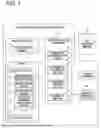
FIG. 1 is a block diagram illustrating a ship propulsion machine control system according to an example of the present disclosure;
FIG. 2 is an explanatory diagram illustrating a boat provided with the ship propulsion machine control system according to the example of the present disclosure;
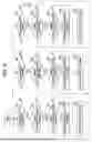
FIG. 3A is an external view of a remote controller in the ship propulsion machine control system according to the example of the present disclosure.
FIG. 3B is an explanatory diagram illustrating a position of a lever of the remote controller.
FIG. 3C is a graph illustrating voltages of two main operation signals output from the remote controller;
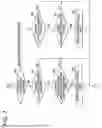
FIG. 4A is an external view of a gauge in the ship propulsion machine control system according to the example of the present disclosure.
FIG. 4B is an explanatory diagram illustrating an information display screen of the gauge.
FIG. 4C is an explanatory diagram illustrating a limp home screen of the gauge;
FIG. 5 is a flowchart illustrating a process flow relating to abnormality detection of a lever position sensor of the remote controller, switching of a control mode of a ship propulsion machine, and switching of an operation mode of the gauge in the ship propulsion machine control system according to the example of the present disclosure;
FIG. 6 is a flowchart illustrating a process flow for controlling the ship propulsion machine based on an operation of the gauge in the ship propulsion machine control system according to the example of the present disclosure;
FIG. 7 is a flowchart illustrating a process flow for controlling the ship propulsion machine based on the operation of the gauge, following FIG. 6;
FIG. 8 is an explanatory diagram illustrating a modification example of the gauge in the ship propulsion machine control system according to the example of the present disclosure; and
FIG. 9A is an explanatory diagram illustrating another example of the ship propulsion machine control system according to the present disclosure; and
FIG. 9B is an explanatory diagram illustrating another example of the ship propulsion machine control system according to the present disclosure.
DESCRIPTION OF EMBODIMENTS
A ship propulsion machine control system according to an embodiment of the present disclosure is a system for controlling a propulsive force for a boat generated by a ship propulsion machine. The ship propulsion machine control system of this embodiment includes an operating device for operating the ship propulsion machine, a gauge for displaying information related to the ship propulsion machine, an abnormality detection section for detecting an abnormality in the operating device, and a control device for controlling the ship propulsion machine in accordance with an operation by a boat operator.
In the ship propulsion machine control system of this embodiment, the operating device has a main operation portion through which the boat operator performs an operation to change a propulsive force of the ship propulsion machine, and a main operation signal output section that outputs a main operation signal in response to the operation of the main operation portion. The gauge has a display unit that displays information related to the ship propulsion machine, a secondary operation unit that allows the boat operator to perform an operation of the ship propulsion machine to change the propulsive force of the ship propulsion machine, and a secondary operation signal output section that outputs a secondary operation signal in response to the operation of the secondary operation unit. When the abnormality detection section does not detect an abnormality in the operating device, the control device changes the propulsive force of the ship propulsion machine based on the main operation signal output from the main operation signal output section of the operating device, and when the abnormality detection section detects an abnormality in the operating device, the control device changes the propulsive force of the ship propulsion machine based on the secondary operation signal output from the secondary operation signal output section of the gauge.
With the ship propulsion machine control system of this embodiment, when the operating device is normal, the boat operator can operate the ship propulsion machine using the main operation portion of the operating device, and when the operating device is abnormal, the boat operator can operate the ship propulsion machine using the secondary operation unit of the gauge. Therefore, when the operating device becomes abnormal and it becomes difficult to use the operating device to operate the ship propulsion machine to move the boat, the boat operator can use the gauge to operate the ship propulsion machine to move the boat. This reduces a degree to which an abnormality such as a failure of the operating device affects performance of navigation, thereby improving safety of navigation.
Example
Hereinafter, an example of a ship propulsion machine control system according to the present disclosure will be described with reference to the drawings.
Ship Propulsion Machine Control System
FIG. 1 illustrates a configuration of a ship propulsion machine control system 1 according to the example of the present disclosure. FIG. 2 illustrates a boat 61 provided with the ship propulsion machine control system 1.
The ship propulsion machine control system 1 is a system configured to control a propulsive force of the boat 61 generated by a ship propulsion machine 51, and is provided on the boat 61. As illustrated in FIG. 1, the ship propulsion machine control system 1 includes a remote controller 2, a gauge 11, a propulsion machine control unit 41, a sound generator 47, and a wireless communication circuit 48.
The remote controller 2 is a device configured to remotely control the ship propulsion machine 51. A boat operator can use the remote controller 2 to switch a shift state of the ship propulsion machine 51 to switch a rotation direction of a propeller of the ship propulsion machine 51. By switching the rotation direction of the propeller, a forward-rearward direction of a propulsive force of the boat 61 generated by the ship propulsion machine 51 is switched, and the boat 61 switches between forward and reverse motion. In addition, the boat operator can use the remote controller 2 to change a rotational speed of an engine of the ship propulsion machine 51 and thereby change a rotational speed of the propeller of the ship propulsion machine 51. As the rotational speed of the propeller changes, magnitude of the propulsive force of the boat 61 generated by the ship propulsion machine 51 changes, and the speed of the boat 61 changes. The remote controller 2 is an example of an "operating device".
The gauge 11 is basically a device configured to display information related to the ship propulsion machine, such as engine rotational speed, shift state, remaining fuel, and the like. However, in this example, the gauge 11 has a function of remotely controlling the ship propulsion machine 51 in place of the remote controller 2, in a case where an abnormality is detected in a lever position sensor 5 of the remote controller 2.
The propulsion machine control unit 41 is a device that has functions of controlling the ship propulsion machine 51 in accordance with an operation of the remote controller 2 or the gauge 11 by the boat operator, acquiring the information related to the ship propulsion machine 51 and sending it to the gauge 11, detecting abnormalities in the lever position sensor 5 of the remote controller 2, and notifying the boat operator or the like that means for operating the ship propulsion machine 51 has been changed from the remote controller 2 to the gauge 11 due to an abnormality in the lever position sensor 5. The propulsion machine control unit 41 is an example of a "control device".
The sound generator 47 is a device configured to emit sounds such as an alarm sound. The sound generator 47 is, for example, a buzzer. The wireless communication circuit 48 is a circuit configured to perform wireless communication between the propulsion machine control unit 41 and an external device. The external device configured to wirelessly communicate with the propulsion machine control unit 41 is, for example, a mobile terminal such as a smartphone.
The remote controller 2, the gauge 11, the sound generator 47, and the wireless communication circuit 48 are each electrically connected to the propulsion machine control unit 41 so as to enable one-way or two-way communication with the propulsion machine control unit 41.
The ship propulsion machine 51, which is a control target of the ship propulsion machine control system 1, is a device configured to generate a propulsive force for the boat 61. Although not illustrated in the figure, the ship propulsion machine 51 includes a propeller configured to generate a propulsive force for the boat 61 by rotating, an engine (internal combustion engine) that is a power source that rotates the propeller, a drive shaft connected to a crankshaft of the engine, a propeller shaft to which the propeller is attached, a gear mechanism configured to connect the drive shaft and the propeller shaft to each other, a clutch configured to switch gears of the gear mechanism to change a rotation direction of the propeller, a shift device configured to control an operation of the clutch, and a drive control device configured to control the engine and the shift device. In addition, the drive control device of the ship propulsion machine 51 is electrically connected to the propulsion machine control unit 41 so as to be able to perform two-way communication with the propulsion machine control unit 41. The drive control device of the ship propulsion machine 51 is a lower-level control device configured to control the ship propulsion machine 51, and the propulsion machine control unit 41 is a higher-level control device configured to control the ship propulsion machine 51.
As illustrated in FIG. 2, the ship propulsion machine 51 is attached to a transom 62 of the boat 61. The remote controller 2 and the gauge 11 are installed in a cockpit 63 of the boat 61. Although not illustrated in FIG. 2, the propulsion machine control unit 41, the sound generator 47, and the wireless communication circuit 48 are installed, for example, near the cockpit 63 in the boat 61.
Remote Controller
The remote controller 2 will be described in detail. FIG. 3A illustrates the remote controller 2. As illustrated in FIG. 3A, the remote controller 2 has an operating device body 3 and a lever 4. The lever 4 is attached to the operating device body 3 so as to be pivotable about its base end relative to the operating device body 3. Furthermore, as illustrated in FIG. 1, the remote controller 2 has the lever position sensor 5 configured to detect a position of the lever 4 (tilt angle of the lever 4). The lever position sensor 5 is disposed inside the operating device body 3. Further, the remote controller 2 is installed in the cockpit 63 of the boat 61 so that a tilt direction of the lever 4 is in a front-rear direction of the boat 61. The lever 4 is an example of a "main operation portion", and the lever position sensor 5 is an example of a "main operation signal output section".
FIG. 3B illustrates the position of the lever 4 of the remote controller 2. As illustrated in FIG. 3B, the boat operator can tilt the lever 4 forward from a neutral position NP through a minimum forward position FP1 to a maximum forward position FP2. In addition, the boat operator can tilt the lever 4 rearward from the neutral position NP through a minimum reverse position RP1 to a maximum reverse position RP2.
The boat operator can switch a shift state of the ship propulsion machine 51 by tilting the lever 4 to change the position of the lever 4. The shift states include neutral, forward, and reverse. Neutral is a state in which the drive shaft and the propeller shaft of the ship propulsion machine 51 are disconnected by the shift device and the clutch, engine power is not transmitted to the propeller, and no propulsive force is generated for the boat. Forward is a state in which, in the ship propulsion machine 51, the drive shaft and the propeller shaft are connected by the shift device and the clutch so that the propeller rotates a forward direction using the power of the engine, generating a propulsive force that moves the boat forward. Reverse is a state in which, in the ship propulsion machine 51, the drive shaft and the propeller shaft are connected by the shift device and the clutch so that the propeller rotates in a reverse direction using the power of the engine, generating a propulsive force that moves the boat backwards. When the lever 4 is in the neutral position NP, the shift state is in neutral. When the position of the lever 4 is between the minimum forward position FP1 and the maximum forward position FP2, the shift state is in forward. When the position of the lever 4 is between the minimum reverse position RP1 and the maximum reverse position RP2, the shift state is in reverse.
In addition, the boat operator can change the rotational speed of the engine of the ship propulsion machine 51 by tilting the lever 4 to change the position of the lever 4. Specifically, in a case where the position of the lever 4 is between the neutral position NP and the minimum forward position FP1, or in a case where the position of the lever 4 is between the neutral position NP and the minimum reverse position RP1, the engine rotational speed becomes an idle speed. Furthermore, in a case where the lever 4 is in a position between the minimum forward position FP1 and the maximum forward position FP2, the engine rotational speed is greater than the idle speed, and as the position of the lever 4 approaches the maximum forward position FP2, the engine rotational speed increases. Furthermore, in a case where the lever 4 is in a position between the minimum reverse position RP1 and the maximum reverse position RP2, the engine rotational speed is greater than the idle speed, and as the position of the lever 4 approaches the maximum reverse position RP2, the engine rotational speed increases.
In addition, the lever position sensor 5 is configured to detect the position of the lever 4 and output two main operation signals, which is a first main operation signal and a second main operation signal, whose voltage is determined according to the position of the lever 4, to the propulsion machine control unit 41. In a case where no abnormality is detected in the lever position sensor 5, the propulsion machine control unit 41 controls the ship propulsion machine 51 based on these two main operation signals, thereby switching the shift state based on the position of the lever 4, and increasing or decreasing the engine rotational speed based on the position of the lever 4.
FIG. 3C illustrates changes in voltage of the two main operation signals relative to the change in position of the lever 4. In FIG. 3C, a voltage V1 of the first main operation signal decreases at a predetermined gradient while the position of the lever 4 changes from the maximum forward position FP2 to the maximum reverse position RP2. Moreover, a voltage V2 of the second main operation signal increases at a predetermined gradient while the position of the lever 4 changes from the maximum forward position FP2 to the maximum reverse position RP2. Moreover, an absolute value of the gradient of the voltage V1 and an absolute value of the gradient of the voltage V2 are equal to each other. Furthermore, when the lever 4 is in the neutral position NP, the voltages V1 and V2 are equal to each other.
Gauge
The gauge 11 will be described in detail. As illustrated in FIG. 1, the gauge 11 includes a gauge control unit 12 and a touch panel display 17. FIG. 4A illustrates an external appearance of the gauge 11. As illustrated in FIG. 4A, the gauge 11 has a casing 18. The gauge control unit 12 and the touch panel display 17 are disposed inside the casing 18. In addition, a display window 18A is formed on one surface of the casing 18. The touch panel display 17 is disposed so that the position of a display area 17A corresponds to the position of the display window 18A. This allows the display area 17A to be viewed from the outside. The gauge 11 is installed in the cockpit 63 of the boat 61 so that the one surface of the casing 18 on which the display window 18A is formed faces upward.
The gauge control unit 12 also includes a Central Processing Unit (CPU), a non-volatile memory, and the like. As illustrated in FIG. 1, the gauge control unit 12 also includes an operation mode setting section 13, a display control section 14, an input detection section 15, and a secondary operation signal output section 16. The operation mode setting section 13, the display control section 14, the input detection section 15, and the secondary operation signal output section 16 are embodied by the CPU of the gauge control unit 12 reading and executing a computer program stored in the non-volatile memory of the gauge control unit 12.
The operation mode setting section 13 is configured to set an operation mode of the gauge 11. The operation modes of the gauge 11 include an information display mode and a limp home mode. The information display mode is a mode in which information related to the ship propulsion machine 51 is displayed. The limp home mode is a mode in which the ship propulsion machine 51 is operated by the gauge 11 in a case where an abnormality is detected in the lever position sensor 5 of the remote controller 2. The information display mode is an example of the "first mode", and the limp home mode is an example of the "second mode".
The display control section 14 is configured to display a screen in the display area 17A of the touch panel display 17 according to the operation mode of the gauge 11, and form a touch switch within the screen.
Specifically, in a case where the operation mode of the gauge 11 is the information display mode, the display control section 14 displays, for example, an information display screen 21 illustrated in FIG. 4B in the display area 17A of the touch panel display 17. A plurality of pieces of information related to the ship propulsion machine 51 are displayed on the information display screen 21. For example, the information display screen 21 displays a number of pieces of information related to the ship propulsion machine 51, such as an engine rotational speed 22, a trim angle 23, an engine temperature 24, a shift state 25, and a remaining fuel 26. In addition, a clock 27 is displayed within the information display screen 21. Furthermore, in a case where the operation mode of the gauge 11 is the information display mode, the display control section 14 forms a menu switch 28 within the information display screen 21. The menu switch 28 is a touch switch for making various settings for the gauge 11 and for manually switching the operation mode of the gauge 11. When the boat operator taps the menu switch 28, the screen in the display area 17A switches to a menu screen, and touch switches for selecting items in the menu are formed within the menu screen. The boat operator can select an item in the menu by tapping the touch switch in the menu screen, and can then perform various settings for the gauge 11 or manually switch the operation mode of the gauge 11 depending on the selected item.
On the other hand, when the operation mode of the gauge 11 is the limp home mode, the display control section 14 displays, for example, a limp home screen 31 illustrated in FIG. 4C in the display area 17A of the touch panel display 17. In the limp home screen 31, for example, the engine rotational speed 22, the shift state 25, and the clock 27 are displayed. In addition, when the operation mode of the gauge 11 is the limp home mode, the display control section 14 forms a neutral select switch 32, a forward select switch 33, a reverse select switch 34, a rotational speed increase switch 35, a rotational speed decrease switch 36, and the menu switch 28 within the limp home screen 31. The neutral select switch 32, the forward select switch 33, the reverse select switch 34, the rotational speed increase switch 35, and the rotational speed decrease switch 36 are touch switches for operating the ship propulsion machine 51 using the gauge 11. By tapping these switches, the boat operator can switch the shift state of the ship propulsion machine 51 and can also change the engine rotational speed of the ship propulsion machine 51. Specifically, the neutral select switch 32 is a switch configured to switch the shift state of the ship propulsion machine 51 to neutral. The forward select switch 33 is a switch configured to switch the shift state of the ship propulsion machine 51 to forward. The reverse select switch 34 is a switch configured to switch the shift state of the ship propulsion machine 51 to reverse. The rotational speed increase switch 35 is a switch configured to increase the rotational speed of the engine of the ship propulsion machine 51. The rotational speed decrease switch 36 is a switch configured to reduce the rotational speed of the engine of the ship propulsion machine 51.
The neutral select switch 32, the forward select switch 33, the reverse select switch 34, the rotational speed increase switch 35, and the rotational speed decrease switch 36 are examples of "secondary operation unit". Furthermore, among these, the neutral select switch 32, the forward select switch 33, and the reverse select switch 34 are examples of a "propulsive force direction change unit", and the rotational speed increase switch 35 and the rotational speed decrease switch 36 are examples of a "propulsive force increase/decrease operation unit".
The input detection section 15 is configured to specify the touch switch that has been tapped. Specifically, in a case where a part of the display area 17A is tapped, the touch panel display 17 outputs a detection signal indicating a tapped position within the display area, or the like to the gauge control unit 12. The input detection section 15 is configured to specify the touch switch that has been tapped based on the detection signal.
In a case where the operation mode of the gauge is the limp home mode, the secondary operation signal output section 16 outputs a secondary operation signal to the propulsion machine control unit 41 in response to a tap of the neutral select switch 32, the forward select switch 33, the reverse select switch 34, the rotational speed increase switch 35, or the rotational speed decrease switch 36. In a case where an abnormality is detected in the lever position sensor 5 of the remote controller 2, the propulsion machine control unit 41 controls the ship propulsion machine 51 based on these secondary operation signals. This enables the shift state to be switched according to the tap of the neutral select switch 32, the forward select switch 33 or the reverse select switch 34, and the engine rotational speed to be increased or decreased according to the tap of the rotational speed increase switch 35 or the rotational speed decrease switch 36.
Propulsion Machine Control Unit
The propulsion machine control unit 41 will be described in detail. The propulsion machine control unit 41 includes a CPU, a non-volatile memory, and the like. As illustrated in FIG. 1, the propulsion machine control unit 41 includes a propulsion machine control section 42, an information transmission section 43, an abnormality detection section 44, and a notification section 45. The propulsion machine control section 42, the information transmission section 43, the abnormality detection section 44, and the notification section 45 are embodied by the CPU of the propulsion machine control unit 41 reading and executing a computer program stored in the non-volatile memory of the propulsion machine control unit 41.
The propulsion machine control section 42 is configured to control the ship propulsion machine 51, based on the main operation signal or the secondary operation signal. Specifically, in a case where no abnormality is detected in the lever position sensor 5 of the remote controller 2, the propulsion machine control section 42 performs control to switch the shift state of the ship propulsion machine 51 and control to increase or decrease the engine rotational speed of the ship propulsion machine 51 based on the two main operation signals output from the lever position sensor 5 of the remote controller 2. On the other hand, in a case where an abnormality is detected in the lever position sensor 5, the propulsion machine control section 42 performs control to switch the shift state of the ship propulsion machine 51 and control to increase or decrease the engine rotational speed of the ship propulsion machine 51 based on the secondary operation signal output from the gauge 11. In addition, in a case where an abnormality is detected in the lever position sensor 5, the propulsion machine control section 42 automatically switches the mode of controlling the ship propulsion machine 51 from a mode of controlling the ship propulsion machine 51 based on a main operation signal to a mode of controlling the ship propulsion machine 51 based on a secondary operation signal.
The information transmission section 43 is configured to acquire information related to the ship propulsion machine 51 and send it to the gauge 11. For example, the drive control device of the ship propulsion machine 51 sends information related to the ship propulsion machine 51, such as the engine rotational speed, engine temperature, shift state, trim angle, and the like of the ship propulsion machine 51 to the propulsion machine control unit 41. The information transmission section 43 sends the information to the gauge 11. Furthermore, in a case where an abnormality in the lever position sensor 5 is detected, the information transmission section 43 sends a lever position sensor abnormality notification signal notifying the gauge 11 of the abnormality in the lever position sensor 5.
The abnormality detection section 44 is configured to detect an abnormality in the lever position sensor 5 of the remote controller 2. In a case where any one of the following lever position sensor abnormality conditions (a) to (f) is satisfied, the lever position sensor 5 is considered to be abnormal.
(a) The voltage V1 of the first main operation signal exceeds a single upper limit threshold.
(b) The voltage V1 of the first main operation signal is below a single lower limit threshold.
(c) The voltage V2 of the second main operation signal exceeds the single upper limit threshold.
(d) The voltage V2 of the second main operation signal is below the single lower limit threshold.
(e) The sum of the voltage V1 of the first main operation signal and the voltage V2 of the second main operation signal exceeds a sum upper limit threshold.
(f) The sum of the voltage V1 of the first main operation signal and the voltage V2 of the second main operation signal is below a sum lower limit threshold.
The abnormality detection section 44 is configured to detect an abnormality in the lever position sensor 5, based on the above-described lever position sensor abnormality conditions (a) to (f). The single upper limit threshold, the single lower limit threshold, the sum upper limit threshold, and the sum lower limit threshold are stored in advance in a non-volatile memory possessed by the propulsion machine control unit 41.
The notification section 45 is configured to notify the boat operator or the like that means for operating the ship propulsion machine 51 has been changed from the remote controller 2 to the gauge 11, in a case where the abnormality detection section 44 detects an abnormality in the lever position sensor 5, in a case where the mode in which the propulsion machine control section 42 controls the ship propulsion machine 51 is switched from the mode of controlling the ship propulsion machine 51 based on the main operation signal to the mode of controlling the ship propulsion machine 51 based on the secondary operation signal, or in a case where the operation mode of the gauge 11 is switched from the information display mode to the limp home mode. The notification section 45 is configured to use the sound generator 47 and the wireless communication circuit 48 to notify that the means for operating the ship propulsion machine 51 has been changed from the remote controller 2 to the gauge 11. Specifically, the notification section 45 is configured to generate a sound from the sound generator 47 to notify that the means for operating the ship propulsion machine 51 has been changed from the remote controller 2 to the gauge 11. In addition, the notification section 45 notifies the boat operator that the means for operating the ship propulsion machine 51 has been changed from the remote controller 2 to the gauge 11 by sending a notification via the wireless communication circuit 48 to a mobile terminal such as a smartphone carried by the boat operator, for example.
Process Flow in Ship Propulsion Machine Control System
Processing relating to abnormality detection of the lever position sensor 5 of the remote controller 2, switching of the control mode of the ship propulsion machine 51, and switching of the operation mode of the gauge 11 in the ship propulsion machine control system 1 will be described. FIG. 5 illustrates the process flow.
When the ship propulsion machine control system 1 starts operating, a mode in which the propulsion machine control section 42 of the propulsion machine control unit 41 controls the ship propulsion machine 51 is in the mode in which the ship propulsion machine 51 is controlled based on the main operation signal output from the lever position sensor 5 of the remote controller 2. Additionally, the operation mode of the gauge 11 is set to the information display mode.
During operation of the ship propulsion machine control system 1, the abnormality detection section 44 of the propulsion machine control unit 41 detects an abnormality in the lever position sensor 5 of the remote controller 2 by executing the process of steps S1 to S7 in FIG. 5. Specifically, in step S1, the abnormality detection section 44 detects the voltage V1 of the first main operation signal and the voltage V2 of the second main operation signal output from the lever position sensor 5. Next, the abnormality detection section 44 uses the detected voltages V1 and V2 to sequentially determine whether the lever position sensor abnormality conditions (a) to (f) are satisfied.
That is, the abnormality detection section 44 first determines whether the voltage V1 exceeds the single upper limit threshold (step S2). When the voltage V1 does not exceed the single upper limit threshold, it is then determined whether the voltage V1 is below the single lower limit threshold (step S3). When the voltage V1 is not below the single lower limit threshold, it is next determined whether the voltage V2 exceeds the single upper limit threshold (step S4). When the voltage V2 does not exceed the single upper limit threshold, it is then determined whether the voltage V2 is below the single lower limit threshold (step S5). When the voltage V2 is not below the single lower limit threshold, it is next determined whether the sum of the voltages V1 and V2 exceeds the sum upper limit threshold (step S6). When the sum of voltages V1 and V2 does not exceed the sum upper limit threshold, it is next determined whether the sum of voltages V1 and V2 is below the sum lower limit threshold (step S7). When the sum of voltages V1 and V2 is not below the sum lower limit threshold, the process returns to step S1.
In this manner, when it is determined in order as to whether the lever position sensor abnormality conditions (a) to (f) are satisfied, and none of the lever position sensor abnormality conditions (a) to (f) are satisfied, it is determined that the lever position sensor 5 is normal. In this case, the process returns to step S1. During operation of the ship propulsion machine control system 1, the abnormality detection section 44 repeatedly executes the process of steps S1 to S7 until any one of the lever position sensor abnormality conditions (a) to (f) is satisfied.
On the other hand, in the process of sequentially determining whether the lever position sensor abnormality conditions (a) to (f) are satisfied, if any one of the lever position sensor abnormality conditions (a) to (f) is satisfied, that is, if the result of any of the determinations in steps S2 to S7 is "YES," it is considered that the lever position sensor 5 is abnormal. In this case, the process proceeds to step S8. Then, in step S8, the propulsion machine control section 42 of the propulsion machine control unit 41 switches the mode of controlling the ship propulsion machine 51 from the mode of controlling the ship propulsion machine 51 based on the main operation signal output from the lever position sensor 5 of the remote controller 2 to the mode of controlling the ship propulsion machine 51 based on the secondary operation signal output from the secondary operation signal output section 16 of the gauge 11.
Next, the information transmission section 43 of the propulsion machine control unit 41 sends a lever position sensor abnormality notification signal notifying the gauge 11 of an abnormality in the lever position sensor 5 (step S9).
Next, the operation mode setting section 13 of the gauge control unit 12 of the gauge 11 recognizes the abnormality of the lever position sensor 5 based on the lever position sensor abnormality notification signal sent from the information transmission section 43, and switches the operation mode of the gauge 11 from the information display mode to the limp home mode (step S10). When the operation mode of the gauge 11 is switched to the limp home mode, the limp home screen 31 illustrated in FIG. 3C is displayed in the display area 17A of the touch panel display 17 of the gauge 11. Also, the neutral select switch 32, the forward select switch 33, the reverse select switch 34, the rotational speed increase switch 35, and the rotational speed decrease switch 36 are formed in the limp home screen 31.
Next, the notification section 45 of the propulsion machine control unit 41 uses the sound generator 47 and the wireless communication circuit 48 to notify the boat operator or the like that the means for operating the ship propulsion machine 51 has been changed from the remote controller 2 to the gauge 11 (step S11).
In this way, when an abnormality is detected in the lever position sensor 5 of the remote controller 2, the mode of controlling the ship propulsion machine 51 automatically switches to a mode in which the ship propulsion machine 51 is controlled based on the secondary operation signal output from the secondary operation signal output section 16 of the gauge 11, and at the same time, the operation mode of the gauge 11 automatically switches to the limp home mode, and thereafter the boat operator is able to operate the ship propulsion machine 51 using the gauge 11.
The operation mode of the gauge 11 can also be manually switched from the information display mode to the limp home mode. For example, the boat operator can tap the menu switch 28 in the information display screen 21 to switch the screen in the display area 17A of the touch panel display 17 to a menu screen. Within the menu screen, touch switches are formed for selecting items in the menu. By tapping the touch switch, the boat operator can select, from the menu, an item for manually switching the operation mode of the gauge 11. When the boat operator selects the item for manually switching the operation mode of the gauge 11, the screen in the display area 17A of the touch panel display 17 is switched to a screen for manually switching the operation mode of the gauge 11. Within the screen, a touch switch for manually switching the operation mode of the gauge 11 is formed. The boat operator can tap the touch switch to switch the operation mode of the gauge 11 to the limp home mode. In addition, in conjunction with the switching of the operation mode of the gauge 11 to the limp home mode, a mode in which the propulsion machine control section 42 controls the ship propulsion machine 51 is switched to a mode of controlling the ship propulsion machine 51 based on a secondary operation signal. The boat operator can manually switch the operation mode of the gauge 11 to the limp home mode and switch the control mode of the ship propulsion machine 51 in conjunction with the manual switching even when no abnormality is detected in the lever position sensor 5 of the remote controller 2.
In addition, when an emergency switch for emergency stop of the ship propulsion machine 51 is provided in the cockpit 63 of the boat 61, the operation mode of the gauge 11 may be switched to the limp home mode when the emergency switch is operated in a special manner, for example, by repeatedly turning the emergency switch on and off a specified number of times within a specified period of time.
Control of Ship Propulsion Machine based on Operation of Gauge
As described above, when an abnormality is detected in the lever position sensor 5 of the remote controller 2, the mode in which the propulsion machine control section 42 of the propulsion machine control unit 41 controls the ship propulsion machine 51 switches to a mode of controlling the ship propulsion machine 51 based on a secondary operation signal, the operation mode of the gauge 11 switches to the limp home mode, and the limp home screen 31 is displayed in the display area 17A of the touch panel display 17, and the limp home screen 31 includes the neutral select switch 32, the forward select switch 33, the reverse select switch 34, the rotational speed increase switch 35, and the rotational speed decrease switch 36. In such a situation, when the boat operator taps the neutral select switch 32, the secondary operation signal output section 16 of the gauge 11 outputs a secondary operation signal including a neutral select command to the propulsion machine control unit 41. In addition, when the boat operator taps the forward select switch 33, the secondary operation signal output section 16 outputs a secondary operation signal including a forward select command to the propulsion machine control unit 41. Furthermore, when the boat operator taps the reverse select switch 34, the secondary operation signal output section 16 outputs a secondary operation signal including a reverse select command to the propulsion machine control unit 41. Furthermore, when the boat operator taps the rotational speed increase switch 35, the secondary operation signal output section 16 outputs a secondary operation signal including a rotational speed increase command to the propulsion machine control unit 41. Furthermore, when the boat operator taps the rotational speed decrease switch 36, the secondary operation signal output section 16 outputs a secondary operation signal including a rotational speed decrease command to the propulsion machine control unit 41. Based on these secondary operation signals, the propulsion machine control section 42 of the propulsion machine control unit 41 performs control to switch the shift state 25 of the ship propulsion machine 51 and control to increase or decrease the engine rotational speed of the ship propulsion machine 51.
Here, the process of controlling the ship propulsion machine 51 based on the operation of the gauge 11, that is, the process of controlling the shift state and engine rotational speed of the ship propulsion machine 51 based on the secondary operation signal output from the secondary operation signal output section 16 of the gauge 11 will be described in detail. FIGS. 6 and 7 illustrate the process flow.
In FIG. 6, when the secondary operation signal output from the secondary operation signal output section 16 of the gauge 11 includes a neutral select command (step S21: YES), the current shift state of the ship propulsion machine 51 is forward or reverse (step S22: YES), and the current engine rotational speed of the ship propulsion machine 51 is higher than the idle speed (step S23: YES), the propulsion machine control section 42 of the propulsion machine control unit 41 sets the engine rotational speed to the idle speed and then switches the shift state to neutral (steps S24, S25). In addition, when the secondary operation signal output from the secondary operation signal output section 16 of the gauge 11 includes a neutral select command (step S21: YES), the current shift state of the ship propulsion machine 51 is forward or reverse (step S22: YES), and the current engine rotational speed of the ship propulsion machine 51 is the idle speed (step S23: NO), the propulsion machine control section 42 switches the shift state to neutral (step S25). In addition, when the secondary operation signal output from the secondary operation signal output section 16 of the gauge 11 includes a neutral select command (step S21: YES) and the current shift state of the ship propulsion machine 51 is neutral (step S22: NO), the propulsion machine control section 42 maintains the neutral shift state. The idle speed is an example of the "predetermined rotational speed".
In addition, when the secondary operation signal output from the secondary operation signal output section 16 of the gauge 11 includes a forward select command (step S21: NO, step S26: YES), the current shift state of the ship propulsion machine 51 is neutral or reverse (step S27: YES), and the current engine rotational speed of the ship propulsion machine 51 is higher than the idle speed (step S28: YES), the propulsion machine control section 42 sets the engine rotational speed to the idle speed and then switches the shift state to forward (steps S29, S30). In addition, when the secondary operation signal output from the secondary operation signal output section 16 of the gauge 11 includes a forward select command (step S21: NO, step S26: YES), the current shift state of the ship propulsion machine 51 is neutral or reverse (step S27: YES), and the current engine rotational speed of the ship propulsion machine 51 is the idle speed (step S28: NO), the propulsion machine control section 42 switches the shift state to forward (step S30). In addition, when the secondary operation signal output from the secondary operation signal output section 16 of the gauge 11 includes a forward select command (step S21: NO, step S26: YES) and the current shift state of the ship propulsion machine 51 is forward (step S27: NO), the propulsion machine control section 42 maintains the forward shift state.
In addition, when the secondary operation signal output from the secondary operation signal output section 16 of the gauge 11 includes a reverse select command (step S21: NO, step S26: NO, step S31: YES), the current shift state of the ship propulsion machine 51 is neutral or forward (step S32: YES), and the current engine rotational speed of the ship propulsion machine 51 is higher than the idle speed (step S33: YES), the propulsion machine control section 42 sets the engine rotational speed to the idle speed and then switches the shift state to reverse (steps S34, S35). In addition, when the secondary operation signal output from the secondary operation signal output section 16 of the gauge 11 includes a reverse select command (step S21: NO, step S26: NO, step S31: YES), the current shift state of the ship propulsion machine 51 is neutral or forward (step S32: YES), and the current engine rotational speed of the ship propulsion machine 51 is idle speed (step S33: NO), the propulsion machine control section 42 switches the shift state to reverse (step S35). In addition, when the secondary operation signal output from the secondary operation signal output section 16 of the gauge 11 includes a reverse select command (step S21: NO, step S26: NO, step S31: YES) and the current shift state of the ship propulsion machine 51 is reverse (step S32: NO), the propulsion machine control section 42 maintains the reverse shift state.
Also, in FIG. 7, when the secondary operation signal output from the secondary operation signal output section 16 of the gauge 11 includes a rotational speed increase command (step S21: NO, step S26: NO, step S31: NO, step S36: YES), the current shift state of the ship propulsion machine 51 is forward or reverse (step S37: YES), and the current engine rotational speed of the ship propulsion machine 51 has not reached a limp home maximum rotational speed (step S38: NO), the propulsion machine control section 42 increases the engine rotational speed (step S39). The limp home maximum rotational speed is a maximum value to which the engine rotational speed can be increased by tapping the rotational speed increase switch 35. The limp home maximum rotational speed is stored in advance in the non-volatile memory provided in the propulsion machine control unit 41. In addition, when the secondary operation signal output from the secondary operation signal output section 16 of the gauge 11 includes a rotational speed increase command (step S21: NO, step S26: NO, step S31: NO, step S36: YES), the current shift state of the ship propulsion machine 51 is forward or reverse (step S37: YES), and the current engine rotational speed of the ship propulsion machine 51 has reached the limp home maximum rotational speed (step S38: YES), the propulsion machine control section 42 does not increase the engine rotational speed. In addition, when the secondary operation signal output from the secondary operation signal output section 16 of the gauge 11 includes a rotational speed increase command (step S21: NO, step S26: NO, step S31: NO, step S36: YES) and the current shift state of the ship propulsion machine 51 is neutral (step S37: NO), the propulsion machine control section 42 does not increase the engine rotational speed.
In addition, when the secondary operation signal output from the secondary operation signal output section 16 of the gauge 11 includes a rotational speed decrease command (step S21: NO, step S26: NO, step S31: NO, step S36: NO), the current shift state of the ship propulsion machine 51 is forward or reverse (step S40: YES), and the current engine rotational speed of the ship propulsion machine 51 is higher than the idle speed (step S41: YES), the propulsion machine control section 42 reduces the engine rotational speed (step S42). In addition, when the secondary operation signal output from the secondary operation signal output section 16 of the gauge 11 includes a rotational speed decrease command (step S21: NO, step S26: NO, step S31: NO, step S36: NO), the current shift state of the ship propulsion machine 51 is forward or reverse (step S40: YES), and the current engine rotational speed of the ship propulsion machine 51 is the idle speed (step S41: NO), the propulsion machine control section 42 maintains the engine rotational speed at the idle speed. In addition, when the secondary operation signal output from the secondary operation signal output section 16 of the gauge 11 includes a rotational speed decrease command (step S21: NO, step S26: NO, step S31: NO, step S36: NO) and the current shift state of the ship propulsion machine 51 is neutral (step S40: NO), the propulsion machine control section 42 does not reduce the engine rotational speed.
As can be seen from steps S23, S24, steps S28, S29, or steps S33, S34 in FIG. 6, when the propulsion machine control section 42 switches the shift state based on the secondary operation signal, if the engine rotational speed is higher than the idle speed, the propulsion machine control section 42 sets the engine rotational speed to the idle speed and then switches the shift state. This makes it possible to suppress an occurrence of large vibrations or shocks in the boat when the shift state is switched. That is, as illustrated in FIG. 3B, when the shift state is switched by the lever 4 of the remote controller 2, the shift state is switched when the position of the lever 4 is between the neutral position NP and the minimum forward position FP1, or when the position of the lever 4 is between the neutral position NP and the minimum reverse position RP1. Therefore, unless the boat operator roughly and quickly moves the lever 4 from, for example, a position between the minimum reverse position RP1 and the maximum reverse position RP2 to a position between the minimum forward position FP1 and the maximum forward position FP2, the engine rotational speed when the shift state is switched will be the idle speed or a value close to the idle speed. Therefore, when the shift state is switched by the lever 4 of the remote controller 2, the vibration or shock of the boat generated when the shift state is switched can be kept small by the boat operator operating the lever slowly and carefully. In contrast, when the shift state is switched using the touch switch of the gauge 11, for example, when the shift state is in reverse and the engine rotational speed is above the idle speed, if the neutral select switch 32 or the forward select switch 33 is tapped and the shift state is changed without controlling the engine rotational speed to the idle speed, the shift state will be switched while the engine rotational speed remains above the idle speed, resulting in large vibrations or shocks to the boat. Indeed, when the boat operator taps the rotational speed decrease switch 36 to bring the engine rotational speed to the idle speed and then taps the neutral select switch 32 or the forward select switch 33, it is possible to prevent large vibrations or shocks from occurring in the boat. However, performing such multiple switch operations is more time-consuming than slowly and carefully operating the lever of the remote controller 2, and so it is not desirable to require the boat operator to do so. In this example, for example, when the shift state is in reverse and the engine rotational speed is higher than the idle speed, when the neutral select switch 32 or the forward select switch 33 is tapped, the engine rotational speed is automatically controlled to be set to the idle speed before the shift state is switched. This makes it possible to prevent large vibrations or shocks from occurring in the boat when the shift state is switched. In addition, the boat operator can set the engine rotational speed to the idle speed and switch the shift state in one go by simply tapping the forward select switch 33 once, which saves time and effort and provides excellent operability.
Furthermore, as can be seen from step S38 in FIG. 7, when the engine rotational speed is increased based on the secondary operation signal, the propulsion machine control section 42 limits the upper limit of the engine rotational speed to the limp home maximum rotational speed. It is preferable to set the limp home maximum rotational speed to a value smaller than a maximum value of normal engine rotational speed, that is, the engine rotational speed when the lever position sensor 5 of the remote controller 2 is normal and the lever 4 of the remote controller 2 is in the maximum forward position FP2. As a result, when an abnormality occurs in the lever position sensor 5 of the remote controller 2, the speed of the boat 61 can be reduced, thereby ensuring safe navigation.
As described above, with the ship propulsion machine control system 1 of this example, when the remote controller 2 is normal, the boat operator can operate the ship propulsion machine 51 using the lever 4 of the remote controller 2, and when the remote controller 2 is abnormal, the boat operator can operate the ship propulsion machine 51 using the touch switch of the gauge 11. Therefore, when the remote controller 2 becomes abnormal and it becomes difficult to use the remote controller 2 to operate the ship propulsion machine 51 to move the boat 61, the boat operator can use the gauge 11 to operate the ship propulsion machine 51 to move the boat. Therefore, it is possible to reduce a degree to which an abnormality such as a failure of the remote controller 2 affects performance of navigation, hereby improving safety of navigation.
Furthermore, in the ship propulsion machine control system 1 of this example, when an abnormality is detected in the lever position sensor 5 of the remote controller 2, the mode of controlling the ship propulsion machine 51 automatically switches from the mode of controlling the ship propulsion machine 51 based on a main operation signal to the mode of controlling the ship propulsion machine 51 based on a secondary operation signal, and the operation mode of the gauge 11 automatically switches from the information display mode to the limp home mode. Therefore, when an abnormality occurs in the remote controller 2, the boat operator can quickly and easily start operating the ship propulsion machine 51 using the gauge 11, and can quickly ensure the safety of the navigation of the boat.
In addition, in the ship propulsion machine control system 1 of this example, when the operation mode of the gauge 11 is the information display mode, the gauge 11 displays the information display screen 21, which does not have touch switches for operating the ship propulsion machine 51, in the display area 17A of the touch panel display 17, and when the operation mode of the gauge 11 is the limp home mode, the gauge 11 displays the limp home screen 31, which has touch switches for operating the ship propulsion machine 51, in the display area 17A of the touch panel display 17. When the ship propulsion machine 51 can be operated using the remote controller 2, the information display screen 21 that does not have touch switches for operating the ship propulsion machine 51 is displayed in the display area 17A of the touch panel display 17, so that a lot of information related to the ship propulsion machine 51 can be displayed in the display area 17A, thereby maintaining or enhancing the basic performance of the gauge 11, which is to display various information related to the ship propulsion machine 51. On the other hand, when the ship propulsion machine 51 cannot be operated using the remote controller 2, the limp home screen 31 having touch switches for operating the ship propulsion machine 51 is displayed in the display area 17A of the touch panel display 17, thereby enabling the ship propulsion machine 51 to be operated using the gauge 11.
In addition, since the gauge 11 is a device that has the role of providing various information related to the ship propulsion machine 51 to the boat operator who is operating the boat, it has a large display and is placed in a place where the boat operator operates the boat, such as the cockpit 63 of the boat 61. The gauge 11 is disposed near the remote controller 2. Therefore, by providing the gauge 11 with a function for operating the ship propulsion machine 51, it is possible to provide an operating device that can serve as a substitute for the remote controller 2 and that has ease of operation similar to that of the remote controller 2. Furthermore, by providing the gauge 11 with a function for operating the ship propulsion machine 51, it is not necessary to provide a separate operating device in the cockpit 63 as a substitute for the remote controller 2, so the number of pieces of equipment installed in the cockpit 63 can be reduced. Therefore, it is possible to make the cockpit 63 more compact, simplify the layout of the devices in the cockpit 63, and simplify the wiring of the devices.
In addition, the ship propulsion machine control system 1 of this example has the notification section 45, and when the mode in which the propulsion machine control section 42 controls the ship propulsion machine 51 is switched from the mode of controlling the ship propulsion machine 51 based on the main operation signal to the mode of controlling the ship propulsion machine 51 based on the secondary operation signal, or when the operation mode of the gauge 11 is switched from the information display mode to the limp home mode, the notification section 45 notifies the boat operator or the like that the means for operating the ship propulsion machine 51 has been changed from the remote controller 2 to the gauge 11. Based on the notification by the notification section 45, the boat operator can easily and quickly know that the means for operating the ship propulsion machine 51 has been changed from the remote controller 2 to the gauge 11. Therefore, when an abnormality occurs in the remote controller 2, the boat operator can quickly start operating the ship propulsion machine 51 using the gauge 11, and can quickly ensure the safety of the navigation of the boat.
In addition, in the ship propulsion machine control system 1 of this example, when the propulsion machine control section 42 switches the shift state of the ship propulsion machine 51 based on the secondary operation signal, if the engine rotational speed of the ship propulsion machine 51 is not the idle speed, the propulsion machine control section 42 sets the engine rotational speed to the idle speed before switching the shift state. This makes it possible to suppress an occurrence of large vibrations or shocks in the boat when the shift state is switched.
In addition, when the operation mode of the gauge 11 in the ship propulsion machine control system 1 of the above-described example is the information display mode, the gauge 11 displays the information display screen 21, which does not have touch switches for operating the ship propulsion machine 51, in the display area 17A of the touch panel display 17, and when the operation mode of the gauge 11 is the limp home mode, the gauge 11 displays the limp home screen 31, which has touch switches for operating the ship propulsion machine 51, in the display area 17A of the touch panel display 17. However, the gauge in the ship propulsion machine control system of the present disclosure is not limited to this. For example, like gauge 71 illustrated in FIG. 8, a gauge control unit (not illustrated) and a display 73 may be provided within a casing 72, the display 73 may be positioned so that its display area 73A corresponds to a display window 72A formed on one side of the casing 72, and a plurality of mechanical switches 74 may be provided outside the display window 72A. When the operation mode of the gauge 71 is the information display mode, none of the plurality of switches 74 may be assigned a function of operating the ship propulsion machine 51, and when the operation mode of the gauge 71 is the limp home mode, all or some of the plurality of switches 74 may be assigned the function of operating the ship propulsion machine 51. Further, when an abnormality is detected in the lever position sensor 5 of the remote controller 2, the operation mode of the gauge 71 may be switched from the information display mode to the limp home mode.
Furthermore, in the ship propulsion machine control system 1 of the above-described example, an example is given in which the remote controller 2 is used as the operating device for operating the ship propulsion machine 51, but the present disclosure is not limited to this. For example, as illustrated in FIG. 9A, a grip 83 of a tiller handle 81 may be used as an operating device for operating a ship propulsion machine 85. As illustrated in FIG. 9B, the grip 83 is provided at a tip of a bar portion 82 of the tiller handle 81. The grip 83 is provided on the bar portion 82 so as to be rotatable from a middle position MP relative to the bar portion 82 in a direction indicated by an arrow FA or a direction indicated by an arrow RA. For example, when the grip 83 is in the middle position MP, the shift state of the ship propulsion machine 85 is in neutral. Furthermore, when the grip 83 is rotated in the direction indicated by the arrow FA, the shift state of the ship propulsion machine 85 is in forward. Furthermore, when the grip 83 is rotated in the direction indicated by the arrow RA, the shift state of the ship propulsion machine 85 is in reverse. Furthermore, when the grip 83 is in the middle position MP, the engine rotational speed of the ship propulsion machine 85 becomes the idle speed. Furthermore, when the grip 83 is rotated in the direction indicated by the arrow FA, the engine rotational speed becomes higher than the idle speed, and the engine rotational speed increases as a rotation angle of the grip 83 in the direction indicated by the arrow FA from the middle position MP becomes larger. Furthermore, when the grip 83 is rotated in the direction indicated by the arrow RA, the engine rotational speed becomes higher than the idle speed, and the engine rotational speed increases as a rotation angle of the grip 83 in the direction indicated by the arrow RA from the middle position MP becomes larger. In addition, a gauge 84 is provided on a base end portion of the bar portion 82. Further, for example, a propulsion machine control unit having a propulsion machine control section, an information transmission section, an abnormality detection section, and a notification section is provided inside the bar portion 82, inside the gauge 84, or in the ship propulsion machine 85. In addition, for example, a sound generator and a wireless communication circuit are provided inside the bar portion 82, inside the gauge 84, or in the ship propulsion machine 85.
Furthermore, in the ship propulsion machine control system 1 of the above-described example, the propulsion machine control unit 41 is separate and independent from the gauge 11, but for example, the propulsion machine control unit 41 may be provided within the casing 18 of the gauge 11 and integrated with the gauge 11. Moreover, the propulsion machine control unit 41 may be provided in the ship propulsion machine 51.
In addition, in the ship propulsion machine control system 1 of the above-described example, the sound generator 47 and the wireless communication circuit 48 are connected to the propulsion machine control unit 41, but the sound generator 47 and the wireless communication circuit 48 may also be connected to the gauge control unit 12.
In addition, in the ship propulsion machine control system 1 of the above-described example, an example is given of a case in which, when an abnormality is detected in the lever position sensor 5 of the remote controller 2, the control mode of the ship propulsion machine 51 and the operation mode of the gauge 11 are switched. However, the present disclosure is not limited to this. When an abnormality is detected in another part of the remote controller 2, the control mode of the ship propulsion machine 51 and the operation mode of the gauge 11 may be switched.
Furthermore, a control target object of the ship propulsion machine control system 1 of the above-described example may be not only a ship propulsion machine that uses an engine as a power source to rotate a propeller, but also a ship propulsion machine that uses a motor (electric motor) as a power source to rotate a propeller. In a ship propulsion machine control system that controls a ship propulsion machine that uses a motor as a power source to rotate a propeller, when switching the shift state of the ship propulsion machine based on a secondary operation signal, if the rotational speed of the motor of the ship propulsion machine is not a predetermined rotational speed (for example, 0), the rotational speed of the motor is set to the above-mentioned predetermined rotational speed before switching the shift state.
Furthermore, the control target object of the ship propulsion machine control system 1 of the present disclosure is not limited to an outboard motor, but may be other ship propulsion machine other than an outboard motor, such as an inboard-outboard motor.
Furthermore, the present invention can be modified as appropriate within the scope that does not deviate from the gist or concept of the invention that can be read from the claims and the entire specification, and a ship propulsion machine control system involving such modifications is also included in the technical concept of the present invention.
Claims
What is claimed is:1. A ship propulsion machine control system for controlling a propulsive force for a boat generated by a ship propulsion machine, the ship propulsion machine control system comprising:
an operating device including:
a main operation portion configured to perform an operation to change the propulsive force; and
a main operation signal output section configured to output a main operation signal according to an operation of the main operation portion;
a gauge including:
a display unit configured to display information related to the ship propulsion machine;
a secondary operation unit configured to perform an operation to change the propulsive force; and
a secondary operation signal output section configured to output a secondary operation signal according to an operation of the secondary operation unit;
an abnormality detection section configured to detect an abnormality in the operating device; and
a control device configured to:
change the propulsive force based on the main operation signal, in a case where no abnormality in the operating device is detected by the abnormality detection section; and
change the propulsive force based on the secondary operation signal, in a case where an abnormality in the operating device is detected by the abnormality detection section.
2. The ship propulsion machine control system according to claim 1,
wherein the display unit is a touch panel display,
the secondary operation unit is a touch switch formed on a screen of the display unit,
the gauge includes an operation mode setting section configured to set an operation mode of the gauge to at least one of a first mode in which the secondary operation unit is not formed on the screen of the display unit, and a second mode in which the secondary operation unit is formed on the screen of the display unit, and
the operation mode setting section is configured to switch the operation mode of the gauge from the first mode to the second mode, in a case where the abnormality detection section detects an abnormality in the operating device while the operation mode of the gauge is the first mode.
3. The ship propulsion machine control system according to claim 1,
wherein the gauge includes a plurality of switches,
the gauge includes an operation mode setting section configured to set an operation mode of the gauge to at least one of a first mode in which a function as the secondary operation unit is not assigned to the plurality of switches, and a second mode in which a function as the secondary operation unit is assigned to the plurality of switches, and
the operation mode setting section is configured to switch the operation mode of the gauge from the first mode to the second mode, in a case where the abnormality detection section detects an abnormality in the operating device while the operation mode of the gauge is the first mode.
4. The ship propulsion machine control system according to claim 1, further comprising:
a notification section configured to notify that means for operating the ship propulsion machine is changed from the operating device to the gauge, in a case where a control mode for changing the propulsive force in the control device is switched from a mode for changing the propulsive force based on the main operation signal to a mode for changing the propulsive force based on the secondary operation signal.
5. The ship propulsion machine control system according to claim 2, further comprising:
a notification section configured to notify that means for operating the ship propulsion machine is changed from the operating device to the gauge, in a case where the operation mode of the gauge is switched from the first mode to the second mode.
6. The ship propulsion machine control system according to claim 1,
wherein the secondary operation unit includes a propulsive force direction change unit for switching a forward-rearward direction of the propulsive force, and a propulsive force increase/decrease operation unit for changing magnitude of the propulsive force.
7. The ship propulsion machine control system according to claim 6,
wherein the control device is configured to change the magnitude of the propulsive force by changing a rotational speed of a power source of the ship propulsion machine, and
in a case where an abnormality is detected in the operating device by the abnormality detection section, and an operation to switch the forward-rearward direction of the propulsive force is performed by the propulsive force direction change unit in a state where the rotational speed of the power source exceeds a predetermined rotational speed, the control device switches the forward-rearward direction of the propulsive force after setting the rotational speed of the power source to the predetermined rotational speed.
Images & Drawings included:


Sources:
- United States Patent and Trademark Office - verify current appl. status at the USPTO↗
Recent applications in this class:
- » 20260077847 2026-03-19
Method and system of governing a boat or the like having a single motor - » 20260062106 2026-03-05
HYBRID DRIVELINE CONTROL - » 20260054820 2026-02-26
HYBRID DRIVELINE CONTROL - » 20260054819 2026-02-26
CLOSED-LOOP AUTOMATIC CONTROL SYSTEM FOR SHIP SPEED AND METHOD THEREOF - » 20260048828 2026-02-19
JET PROPULSION BOAT AND METHOD OF CONTROLLING JET PROPULSION BOAT - » 20250368308 2025-12-04
PROPULSION ARRANGEMENT FOR MARINE VESSEL WITH CROSS-OVER FUNCTIONALITY - » 20250304232 2025-10-02
DUAL STEERING SYSTEM AND RELATED BOAT - » 20250289554 2025-09-18
INFORMATION PROCESSING METHOD AND PROGRAM - » 20250249996 2025-08-07
METHOD AND APPARATUS FOR CONTROLLING WATERJET-DRIVEN MARINE VESSEL - » 20250214694 2025-07-03
WATERCRAFT DEVICE WITH A HANDHELD CONTROLLER
Recent applications for this Assignee:
- » 20260104470 2026-04-16
BATTERY DIAGNOSTIC DEVICE FOR ELECTRIC PROPULSION MACHINE AND SHIP PROPULSION SYSTEM - » 20260098787 2026-04-09
MISFIRE DIAGNOSIS DEVICE - » 20260098786 2026-04-09
MISFIRE DIAGNOSIS DEVICE - » 20260092588 2026-04-02
IGNITION DEVICE - » 20260084795 2026-03-26
OUTBOARD MOTOR - » 20260084794 2026-03-26
OUTBOARD MOTOR - » 20260062089 2026-03-05
ENGINE - » 20260062088 2026-03-05
FRAME STRUCTURE - » 20260055721 2026-02-26
ELECTRIC PROPULSION MACHINE - » 20260054818 2026-02-26
MARINE PROPULSION DEVICE