TERMINAL TAPE CONVEYING DEVICE
US20260109562A1
2026-04-23
19/365,290
2025-10-22
Smart Summary: A terminal tape conveying device helps move terminal tapes smoothly. It has two channels that face each other and run in a straight line. There are also two driving devices that push the terminal tapes along these channels. Each driving device uses friction wheels that grip a belt to move the tapes forward. This setup ensures the terminal tapes are guided and transported effectively. 🚀 TL;DR
Abstract:
A terminal tape conveying device includes a pair of conveying channels facing each other in a transverse direction and extending in a longitudinal direction perpendicular to the transverse direction, and a pair of driving devices spaced apart in the longitudinal direction and driving a pair of terminal tapes such that the terminal tapes move along the conveying channels. The conveying channels carry the terminal tapes and respectively guide movements of the terminal tapes. Each driving device has a pair of friction wheels clamping a carrier belt for the terminal tapes and rotating about a transverse axis to drive the terminal tapes to move along the conveying channels by friction.
Inventors:
- Roberto Francisco-Yi Lu 176 🇺🇸 Bellevue, WA, United States
- Lvhai (Samuel) Hu 50 🇨🇳 Shanghai, China
- Dandan (Emily) Zhang 64 🇨🇳 Shanghai, China
- An (Joshua) Yang 40 🇨🇳 Shanghai, China
- Lei (Alex) Zhou 34 🇨🇳 Shanghai, China
- Yanlu Dong 1 🇨🇳 Qingdao, China
Assignee:
- TYCO ELECTRONICS (SHANGHAI) CO., LTD. 909 🇨🇳 Shanghai, China
- Tyco Electronics (Qingdao) Ltd. 3 🇨🇳 Qingdao, China
- TE Connectivity Solutions GMBH 492 🇨🇭 Schaffhausen, Switzerland
Applicant:
Interested in similar patents?
Get notified when new applications in this technology area are published.
Description
CROSS-REFERENCE TO RELATED APPLICATIONS
This application claims the benefit of Chinese Patent Application No. 202411480697.7, filed on Oct. 22, 2024.
FIELD OF THE INVENTION
The present invention relates to a terminal tape conveying device.
BACKGROUND OF THE INVENTION
A terminal tape conveying device typically has only a single conveying channel, which can only convey a single terminal tape at a time. The existing terminal tape conveying device has a low conveying efficiency. In addition, the terminal tape conveying device typically uses pin wheels to drive the terminal tape to move along the conveying channel. Pins on the pin wheels are engaged with positioning holes on the terminal tape. As the pin wheels rotate, the pin wheels push the terminal tape to move along the conveying channel. However, the existing terminal tape conveying device can only convey the same type of terminal tapes, because the pin wheels cannot be engaged with terminal tapes having different pitches.
SUMMARY OF THE INVENTION
A terminal tape conveying device includes a pair of conveying channels facing each other in a transverse direction and extending in a longitudinal direction perpendicular to the transverse direction, and a pair of driving devices spaced apart in the longitudinal direction and driving a pair of terminal tapes such that the terminal tapes move along the conveying channels. The conveying channels carry the terminal tapes and respectively guide movements of the terminal tapes. Each driving device has a pair of friction wheels clamping a carrier belt for the terminal tapes and rotating about a transverse axis to drive the terminal tapes to move along the conveying channels by friction.
BRIEF DESCRIPTION OF DRAWINGS
In the following, the present invention is described in more detail with references to the drawings in which:
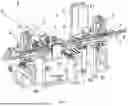
FIG. 1 shows an illustrative perspective view of a terminal tape conveying device according to an exemplary embodiment of the present disclosure, as viewed from one side;
FIG. 2 shows an illustrative perspective view of a terminal tape conveying device according to an exemplary embodiment of the present disclosure, as viewed from the other side;
FIG. 3 shows an illustrative perspective view of a driving device of a terminal tape conveying device according to an exemplary embodiment of the present disclosure;
FIG. 4 shows an illustrative perspective view of supporting devices and a spacing adjusting device of a terminal tape conveying device according to an exemplary embodiment of the present disclosure; and
FIG. 5 shows an illustrative perspective view of pressing devices and counting sensors of a terminal tape conveying device according to an exemplary embodiment of the present disclosure.
DETAILED DESCRIPTION
Exemplary embodiments of the present disclosure will be described hereinafter in detail with reference to the attached drawings, wherein like reference numerals refer to like elements. The present disclosure may, however, be embodied in many different forms and should not be construed as being limited to the embodiments set forth herein; rather, these embodiments are provided so that the present disclosure will convey the concept of the disclosure to those skilled in the art.
In the following detailed description, for purposes of explanation, numerous specific details are set forth in order to provide a thorough understanding of the disclosed embodiments. It will be apparent, however, that one or more embodiments may be practiced without these specific details. In other instances, well-known structures and devices are schematically shown in order to simplify the drawing.
As shown in FIGS. 1 to 5, in an exemplary embodiment of the present invention, a terminal tape conveying device is disclosed. The terminal tape conveying device includes: two conveying channels 1 and two driving devices 2. The two conveying channels 1 face each other in a transverse direction X and extend in a longitudinal direction Y perpendicular to the transverse direction X, and are configured to carry two terminal tapes 9 and guide movements of the two terminal tapes, respectively. The two driving devices 2 are spaced apart in the longitudinal direction Y and configured to drive the two terminal tapes 9 such that the two terminal tapes 9 move along the two conveying channels 1, respectively. Each of the driving devices 2 comprises a pair of friction wheels 20, and the pair of friction wheels 20 are adapted to clamp a carrier belt for the terminal tapes 9 and adapted to rotate about a transverse axis respectively, so as to drive the terminal tapes 9 to move along the conveying channels 1 by friction.
As shown in FIGS. 1 to 5, in the illustrated embodiment, the two terminal tapes 9 being conveyed face each other and are oriented in opposite orientations. Therefore, the present invention is capable of simultaneously conveying two terminal tapes 9 in opposite orientations, thereby improving conveying efficiency. Moreover, the present invention is applicable to convey terminal tapes 9 having different pitches, thereby expanding the range of application of the terminal tape conveying device.
As shown in FIG. 3, in the illustrated embodiment, the driving device 2 further includes: a fixed mount 21; a movable base 22; and a movable block 23. The movable base 22 is movably mounted onto the fixed mount 21 and is capable of moving in the transverse direction X. The movable block 23 is movably mounted onto the movable base 22 and is capable of moving in a height direction Z. One of the pair of friction wheels 20 is rotatably mounted onto the movable base 22 and the other one is rotatably mounted onto the movable block 23.
As shown in FIGS. 3, in the illustrated embodiment, the driving device 2 further includes a linear electric cylinder 24 mounted onto the fixed mount 21 and connected to the movable base 22. The linear electric cylinder 24 is configured to drive the movable base 22 to move in the transverse direction X to adjust positions of the pair of friction wheels 20 in the transverse direction X.
As shown in FIG. 3, in the illustrated embodiment, the pair of friction wheels 20 include an upper friction wheel 20a and a lower friction wheel 20b opposite each other in the height direction Z. The driving device 2 further includes an electric motor 25, mounted onto the movable base 22 and connected to the lower friction wheel 20b, and is configured to drive the lower friction wheel 20b to rotate.
As shown in FIG. 3, in the illustrated embodiment, the upper friction wheel 20a is rotatably mounted onto the movable block 23. The driving device 2 further includes a first spring 26, compressed between the movable base 22 and the movable block 23, and is configured to apply a downward pressure to the upper friction wheel 20a to ensure that the pair of friction wheels 20 are reliably and frictionally engaged with the carrier belt for the terminal tapes 9.
As shown in FIG. 4, in the illustrated embodiment, the terminal tape conveying device further includes a plurality of supporting devices 4 spaced apart in the longitudinal direction Y and configured to support the two conveying channels 1. One of the two conveying channels 1 is movably mounted onto the plurality of supporting devices 4 such that the conveying channel 1 is capable of moving in the transverse direction X.
As shown in FIG. 4, in the illustrated embodiment, the supporting device 4 includes: a support 40; a slide rail 41; and a slider 42. The slide rail 41 extends in the transverse direction X and is fixed to the support 40. The slider 42 is fixed to the bottom of the conveying channel 1. The slider 42 is in sliding fit with the slide rail 41 such that the conveying channel 1 is capable of moving along the slide rail 41.
As shown in FIGS. 1 and 4, in the illustrated embodiment, the terminal tape conveying device further includes a spacing adjusting device 3 connected to the conveying channel 1 and configured to drive the conveying channel 1 to move in the transverse direction X so as to adjust a spacing between the two conveying channels 1.
As shown in FIG. 4, in the illustrated embodiment, the spacing adjusting device 3 includes: a support base 30 and a driver 31. The driver 31 is mounted onto the support base 30 and is connected to the conveying channel 1. The driver 31 is configured to drive the conveying channel 1 to move in the transverse direction X so as to adjust the spacing between the two conveying channels 1. In an embodiment, the aforementioned driver 31 is an electric cylinder, an air cylinder or a hydraulic cylinder.
As shown in FIGS. 1, 2, and 5, in the illustrated embodiment, the terminal tape conveying device further includes a plurality of counting sensors 8 mounted onto the two conveying channels 1 respectively and configured to count the number of terminals on the terminal tapes 9 which are conveyed therethrough.
In an embodiment, the terminal tape conveying device further includes a cutting device for cutting off the terminal tapes 9. When the counting sensors 8 detect that a predetermined number of terminals are conveyed, the cutting device cuts off the terminal tapes 9, so that a section of each terminal tape 9 that is cut off has a predetermined number of terminals.
As shown in FIGS. 1, 2, and 5, in the illustrated embodiment, the terminal tape conveying device further includes a plurality of pressing devices 7 mounted onto the two conveying channels 1 respectively and configured to press the terminal tapes 9 to ensure that the terminal tapes 9 remain straight during conveying.
As shown in FIG. 5, in the illustrated embodiment, the pressing device 7 includes: a frame 70; a press block 71; a press roller 73; and a second spring 72. The frame 70 is fixed onto the conveying channel 1. The press block 71 is movably mounted in the frame 70 and is capable of moving in a height direction Z. The press roller 73 is rotatably mounted onto the press block 71. The second spring 72 is compressed between the frame 70 and the press block 71 and configured to apply a downward pressure to the press block 71 and the press roller 73. The press roller 73 is configured to press on the conveyed terminal tape 9 to avoid bending of the terminal tape 9 during conveying.
As shown in FIG. 1, in the illustrated embodiment, the terminal tape conveying device further includes: a horizontal inspection device 5; a vertical inspection device 6; and a quality determination device. The horizontal inspection device 5 is for taking images of terminals on the conveyed terminal tapes 9 in the transverse direction X. The vertical inspection device 6 is for taking images of the terminals on the conveyed terminal tapes 9 in the height direction Z. The quality determination device is for determining whether the terminals are qualified based on the images of the terminals taken by the horizontal inspection device 5 and the vertical inspection device 6.
As shown in FIG. 1, in the illustrated embodiment, the horizontal inspection device 5 includes: a horizontal camera 51; a horizontal light source 52; and a first bracket 53. The horizontal camera 51 is disposed on one side of the two conveying channels 1 in the transverse direction X and configured to take images of the terminals on the terminal tapes 9 in the transverse direction X. The horizontal light source 52 is disposed on the other side of the two conveying channels 1 in the transverse direction X and opposite the horizontal camera 51 and configured to provide illumination for the horizontal camera 51. The horizontal camera 51 and the horizontal light source 52 are mounted onto the first bracket 53. The quality determination device determines whether the terminals are qualified based on the images of the terminals taken by the horizontal camera 51.
In the illustrated embodiment, the horizontal camera 51 is movably mounted onto the first bracket 53 and capable of moving in the transverse direction X. The horizontal inspection device 5 further includes a first driver 54, mounted onto the first bracket 53 and connected to the horizontal camera 51, and is configured to drive the horizontal camera 51 to move in the transverse direction X.
As shown in FIGS. 1 and 2, in the illustrated embodiment, the vertical inspection device 6 includes: a vertical camera 61; a vertical light source 62; and a second bracket 63. The vertical camera 61 is disposed above the two conveying channels 1 and is configured to take images of the terminals on the terminal tapes 9 in the height direction Z. The vertical light source 62 is disposed below the two conveying channels 1 and opposite the vertical camera 61 and is configured to provide illumination for the vertical camera 61. The vertical camera 61 and the vertical light source 62 are mounted onto the second bracket 63. The quality determination device determines whether the terminals are qualified based on the images of the terminals taken by the vertical camera 61.
In the illustrated embodiment, the vertical camera 61 is movably mounted onto the second bracket 63 and capable of moving in the height direction (Z). The vertical inspection device 6 further includes a second driver, mounted onto the second bracket 63 and connected to the vertical camera 61, and is configured to drive the vertical camera 61 to move in the height direction Z.
In the aforementioned exemplary embodiments according to the present disclosure, a terminal tape conveying device is capable of simultaneously conveying two terminal tapes in opposite orientations. Furthermore, the terminal tape conveying device uses friction wheels to drive the terminal tapes to move along conveying channels, and accordingly is applicable to convey terminal tapes having different pitches, thereby expanding the range of application of the terminal tape conveying device.
Moreover, in each of the aforementioned exemplary embodiments according to the present disclosure, a spacing between two conveying channels can be adjusted such that the terminal tape conveying device is applicable to terminal tapes having terminals of different lengths, further expanding the range of application of the terminal tape conveying device.
It should be appreciated for those skilled in this art that the above embodiments are intended to be illustrative, and not restrictive. For example, many modifications may be made to the above embodiments by those skilled in this art, and various features described in different embodiments may be freely combined with each other without conflicting in configuration or principle.
Although several exemplary embodiments have been shown and described, it would be appreciated by those skilled in the art that various changes or modifications may be made in these embodiments without departing from the principles and spirit of the disclosure, the scope of which is defined in the claims and their equivalents.
As used herein, an element recited in the singular and preceded with the word “a” or “an” should be understood as not excluding plural of said elements or steps, unless such exclusion is explicitly stated. Furthermore, references to “one embodiment” of the present invention are not intended to be interpreted as excluding the existence of additional embodiments that also incorporate the recited features. Moreover, unless explicitly stated to the contrary, embodiments “comprising” or “having” an element or a plurality of elements having a particular property may include additional such elements not having that property.
Claims
What is claimed is:1. A terminal tape conveying device, comprising:
a pair of conveying channels facing each other in a transverse direction and extending in a longitudinal direction perpendicular to the transverse direction, the conveying channels carrying a pair of terminal tapes and respectively guiding movements of the terminal tapes; and
a pair of driving devices spaced apart in the longitudinal direction and driving the terminal tapes such that the terminal tapes move along the conveying channels, each driving device has a pair of friction wheels clamping a carrier belt for the terminal tapes and rotating about a transverse axis to drive the terminal tapes to move along the conveying channels by friction.
2. The terminal tape conveying device of claim 1, wherein each of the driving devices further includes a fixed mount, a movable base movably mounted onto the fixed mount and movable in the transverse direction, and a movable block movably mounted onto the movable base and movable in a height direction, one of the pair of friction wheels is rotatably mounted onto the movable base and the other one is rotatably mounted onto the movable block.
3. The terminal tape conveying device of claim 2, wherein each of the driving devices further includes a linear electric cylinder mounted onto the fixed mount and connected to the movable base, the linear electric cylinder drives the movable base to move in the transverse direction to adjust a pair of positions of the pair of friction wheels in the transverse direction.
4. The terminal tape conveying device of claim 3, wherein the pair of friction wheels include an upper friction wheel and a lower friction wheel opposite each other in the height direction, each of the driving devices further includes an electric motor mounted onto the movable base and connected to the lower friction wheel, the electric motor driving the lower friction wheel to rotate.
5. The terminal tape conveying device of claim 4, wherein the upper friction wheel is rotatably mounted onto the movable block, each of the driving devices includes a first spring compressed between the movable base and the movable block and applying a downward pressure to the upper friction wheel to ensure that the pair of friction wheels are reliably and frictionally engaged with the carrier belt.
6. The terminal tape conveying device of claim 1, further comprising a plurality of supporting devices spaced apart in the longitudinal direction and supporting the conveying channels, one of the conveying channels is movably mounted onto the plurality of supporting devices such that the one of the conveying channels is movable in the transverse direction.
7. The terminal tape conveying device of claim 6, wherein each of the supporting devices includes a support, a slide rail extending in the transverse direction and fixed to the support, and a slider fixed to a bottom of one of the conveying channels, the slider is in sliding fit with the slide rail such that the one of the conveying channels is movable along the slide rail.
8. The terminal tape conveying device of claim 7, further comprising a spacing adjusting device connected to the one of the conveying channels and driving the one of the conveying channels to move in the transverse direction to adjust a spacing between the conveying channels.
9. The terminal tape conveying device of claim 8, wherein the spacing adjusting device includes a support base and a driver mounted onto the support base and connected to the conveying channel, the driver drives the conveying channel to move in the transverse direction so as to adjust the spacing between the conveying channels.
10. The terminal tape conveying device of claim 9, wherein the driver is an electric cylinder, an air cylinder, or a hydraulic cylinder.
11. The terminal tape conveying device of claim 1, further comprising a plurality of counting sensors respectively mounted onto the conveying channels and counting a number of terminals on the terminal tapes which are conveyed therethrough.
12. The terminal tape conveying device of claim 11, further comprising a cutting device cutting off the terminal tapes, when the counting sensors detect that a predetermined number of terminals are conveyed, the cutting device cuts off the terminal tapes, so that a section of each terminal tape that is cut off has the predetermined number of terminals.
13. The terminal tape conveying device of claim 12, further comprising a plurality of pressing devices respectively mounted onto the conveying channels respectively and pressing the plurality of terminal tapes to ensure that the plurality of terminal tapes remain straight during conveying.
14. The terminal tape conveying device of claim 13, wherein each of the pressing devices includes a frame fixed onto one of the conveying channels, a press block movably mounted in the frame and capable of moving in a height direction, a press roller rotatably mounted onto the press block, a second spring compressed between the frame and the press block and applying a downward pressure to the press block and the press roller, the press roller presses a conveyed terminal tape to avoid bending of the conveyed terminal tape during conveying.
15. The terminal tape conveying device of claim 1, further comprising a horizontal inspection device taking a plurality of images of terminals on a plurality of conveyed terminal tapes in the transverse direction, a vertical inspection device taking the images of the terminals on the plurality of conveyed terminal tapes in a height direction, and a quality determination device determining whether the terminals are qualified based on the images of the terminals taken by the horizontal inspection device and the vertical inspection device.
16. The terminal tape conveying device of claim 15, wherein the horizontal inspection device includes a horizontal camera disposed on one side of the conveying channels in the transverse direction and taking the images of the terminals on the plurality of terminal tapes in the transverse direction, a horizontal light source disposed on the other side of the conveying channels in the transverse direction and opposite the horizontal camera and providing illumination for the horizontal camera, a first bracket, the horizontal camera, and the horizontal light source are mounted onto the first bracket, the quality determination device determines whether the terminals are qualified based on the images of the terminals taken by the horizontal camera.
17. The terminal tape conveying device of claim 16, wherein the horizontal camera is movably mounted onto the first bracket and capable of moving in the transverse direction.
18. The terminal tape conveying device of claim 17, wherein the horizontal inspection device further comprises a first driver mounted onto the first bracket and connected to the horizontal camera, the first driver driving the horizontal camera to move in the transverse direction.
19. The terminal tape conveying device of claim 15, wherein the vertical inspection device comprises a vertical camera disposed above the conveying channels and taking the images of the terminals on the plurality of terminal tapes in the height direction, a vertical light source disposed below the conveying channels and opposite the vertical camera and providing illumination for the vertical camera, and a second bracket, the vertical camera and the vertical light source being mounted onto the second bracket, the quality determination device determines whether the terminals are qualified based on the images of the terminals taken by the vertical camera.
20. The terminal tape conveying device of claim 19, wherein the vertical camera is movably mounted onto the second bracket and movable in the height direction, the vertical inspection device further comprises a second driver mounted onto the second bracket and connected to the vertical camera, the second driver driving the vertical camera to move in the height direction.
Images & Drawings included:


Sources:
- United States Patent and Trademark Office - verify current appl. status at the USPTO↗
Recent applications in this class:
- » 20260015197 2026-01-15
FORWARD FEED SUPPLY DEVICE FOR A BAND MATERIAL - » 20260001739 2026-01-01
SHRINK CONVEYOR AND METHOD FOR ALLOWING SHRINK IN A CONTINUOUS STRIP - » 20250333258 2025-10-30
MEDIUM TRANSPORT DEVICE AND RECORDING DEVICE - » 20250230009 2025-07-17
HEAT TREATMENT APPARATUS AND GUIDE ROLLER FOR HEAT TREATMENT APPARATUS - » 20250145400 2025-05-08
SHEET CONVEYING APPARATUS AND PRINTER - » 20250074735 2025-03-06
CONVEYING APPARATUS, CONTROLLER, CONTROL METHOD, AND MEDIUM STORING PROGRAM FOR CONVEYING APPARATUS - » 20250002285 2025-01-02
Electrode Fabric Transfer Device, and Electrode Notching Device Comprising the Same - » 20240375902 2024-11-14
SHRINK CONVEYOR AND METHOD FOR ALLOWING SHRINK IN A CONTINUOUS STRIP - » 20240166460 2024-05-23
ROLLER, INSPECTION METHOD AND APPARATUS, COIL CONVEYING METHOD AND APPARATUS, DEVICE AND MEDIUM - » 20240158195 2024-05-16
CONVEYOR ADAPTED FOR BATTERY MANUFACTURING PROCESS
Recent applications for this Assignee:
- » 20260112870 2026-04-23
Cable Aluminum Foil Stripping Tool, Aluminum Foil Stripping Device And Aluminum Foil Stripping Method - » 20260112870 2026-04-23
Cable Aluminum Foil Stripping Tool, Aluminum Foil Stripping Device And Aluminum Foil Stripping Method - » 20260112847 2026-04-23
GROUNDING SPRING, GROUNDING TERMINAL ASSEMBLY AND CONNECTOR - » 20260112845 2026-04-23
User Configurable Keyable Guide Pin/Module - » 20260108965 2026-04-23
HOT-BAR SOLDERING METHOD AND HOT-BAR SOLDERING SYSTEM - » 20260108965 2026-04-23
HOT-BAR SOLDERING METHOD AND HOT-BAR SOLDERING SYSTEM - » 20260106614 2026-04-16
Contactor Control System - » 20260106613 2026-04-16
Contactor Starting Circuit and Contactor Control System - » 20260106405 2026-04-16
CONNECTOR HOUSING, CONNECTOR ASSEMBLY, AND ASSEMBLY METHOD - » 20260106390 2026-04-16
GUIDE, BOARD CARD ASSEMBLY AND CONNECTOR ASSEMBLY